2022 CHRYSLER PACIFICA panel
[x] Cancel search: panelPage 259 of 384

SAFETY257
Supplemental Driver And Front Passenger
Knee Air Bags
This vehicle is equipped with a Supplemental
Driver Knee Air Bag mounted in the instrument
panel below the steering column and a
Supplemental Passenger Knee Air Bag mounted in
the instrument panel below the glove
compartment. The Supplemental Knee Air Bags
provide enhanced protection during a frontal
impact by working together with the seat belts,
pretensioners, and front air bags.
Supplemental Side Air Bags
Supplemental Seat-Mounted Side Air Bags (SABs)
This vehicle is equipped with Supplemental
Seat-Mounted Side Air Bags (SABs).
Supplemental Seat-Mounted Side Air Bags (SABs)
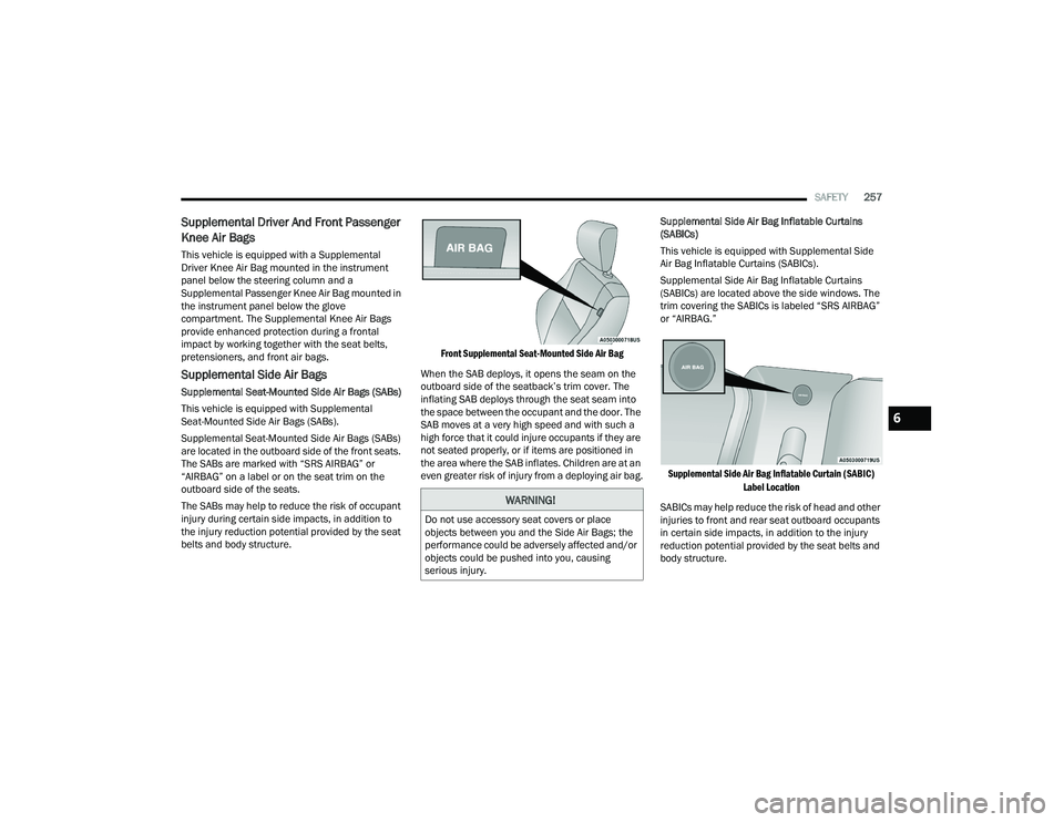
are located in the outboard side of the front seats.
The SABs are marked with “SRS AIRBAG” or
“AIRBAG” on a label or on the seat trim on the
outboard side of the seats.
The SABs may help to reduce the risk of occupant
injury during certain side impacts, in addition to
the injury reduction potential provided by the seat
belts and body structure.
Front Supplemental Seat-Mounted Side Air Bag
When the SAB deploys, it opens the seam on the
outboard side of the seatback’s trim cover. The
inflating SAB deploys through the seat seam into
the space between the occupant and the door. The
SAB moves at a very high speed and with such a
high force that it could injure occupants if they are
not seated properly, or if items are positioned in
the area where the SAB inflates. Children are at an
even greater risk of injury from a deploying air bag. Supplemental Side Air Bag Inflatable Curtains
(SABICs)
This vehicle is equipped with Supplemental Side
Air Bag Inflatable Curtains (SABICs).
Supplemental Side Air Bag Inflatable Curtains
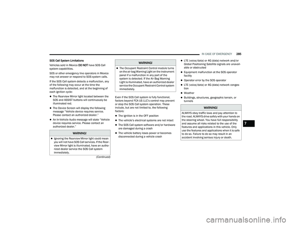
(SABICs) are located above the side windows. The
trim covering the SABICs is labeled “SRS AIRBAG”
or “AIRBAG.”
Supplemental Side Air Bag Inflatable Curtain (SABIC) Label Location
SABICs may help reduce the risk of head and other
injuries to front and rear seat outboard occupants
in certain side impacts, in addition to the injury
reduction potential provided by the seat belts and
body structure.
WARNING!
Do not use accessory seat covers or place
objects between you and the Side Air Bags; the
performance could be adversely affected and/or
objects could be pushed into you, causing
serious injury.
6
22_RUP_OM_EN_USC_t.book Page 257
Page 261 of 384

SAFETY259
NOTE:Air bag covers may not be obvious in the interior
trim, but they will open during air bag deployment.
Rollover Events
Side Air Bags and seat belt pretensioners are
designed to activate in certain rollover events. The
Occupant Restraint Controller (ORC) determines
whether deployment in a particular rollover event
is appropriate, based on the severity and type of
collision. Vehicle damage by itself is not a good
indicator of whether or not Side Air Bags and seat
belt pretensioners should have deployed. The Side Air Bags and seat belt pretensioners will
not deploy in all rollover events. The rollover
sensing system determines if a rollover event may
be in progress and whether deployment is
appropriate. In the event the vehicle experiences a
rollover or near rollover event, and deployment is
appropriate, the rollover sensing system will deploy
the side air bags and seat belt pretensioners on
both sides of the vehicle.
The SABICs may help reduce the risk of partial or
complete ejection of vehicle occupants through
side windows in certain rollover or side impact
events.
Air Bag System Components
NOTE:The Occupant Restraint Controller (ORC) monitors
the internal circuits and interconnecting wiring
associated with electrical Air Bag System Compo
-
nents listed below:
Occupant Restraint Controller (ORC)
Air Bag Warning Light
Steering Wheel and Column
Instrument Panel
Knee Impact Bolsters
Driver and Front Passenger Air Bags
Seat Belt Buckle Switch
Supplemental Side Air Bags
Supplemental Knee Air Bags
Front and Side Impact Sensors
Seat Belt Pretensioners
Seat Track Position Sensors
Occupant Classification System
If A Deployment Occurs
The front air bags are designed to deflate
immediately after deployment.
NOTE:Front and/or side air bags will not deploy in all colli -
sions. This does not mean something is wrong with
the air bag system.
If you do have a collision which deploys the air
bags, any or all of the following may occur:
The air bag material may sometimes cause
abrasions and/or skin reddening to the occu -
pants as the air bags deploy and unfold. The
abrasions are similar to friction rope burns or
those you might get sliding along a carpet or
gymnasium floor. They are not caused by
contact with chemicals. They are not permanent
and normally heal quickly. However, if you
haven’t healed significantly within a few days, or
if you have any blistering, see your doctor imme -
diately.
WARNING!
Side Air Bags need room to inflate. Do not lean
against the door or window. Sit upright in the
center of the seat.
Being too close to the Side Air Bags during
deployment could cause you to be severely
injured or killed.
Relying on the Side Air Bags alone could lead
to more severe injuries in a collision. The Side
Air Bags work with your seat belt to restrain
you properly. In some collisions, Side Air Bags
won’t deploy at all. Always wear your seat belt
even though you have Side Air Bags.
6
22_RUP_OM_EN_USC_t.book Page 259
Page 263 of 384

SAFETY261
(Continued)
NOTE:After an accident, remember to cycle the ignition to
the STOP (OFF/LOCK) position and remove the key
from the ignition switch to avoid draining the
battery. Carefully check the vehicle for fuel leaks in
the engine compartment and on the ground near
the engine compartment and fuel tank before
resetting the system and starting the engine. If
there are no fuel leaks or damage to the vehicle
electrical devices (e.g. headlights) after an
accident, reset the system by following the
procedure described below. If you have any doubt,
contact an authorized dealer.
Enhanced Accident Response System
Reset Procedure
If applicable, refer to the “Hybrid Supplement” for
additional information.
In order to reset the Enhanced Accident Response
System functions after an event, the ignition switch
must be changed from ignition START or ON/RUN
to ignition OFF. Carefully check the vehicle for fuel
leaks in the engine compartment and on the
ground near the engine compartment and fuel
tank before resetting the system and starting the
engine. After an accident, if the vehicle will not start after
performing the reset procedure, the vehicle must
be towed to an authorized dealer to be inspected
and to have the Enhanced Accident Response
System reset.
Maintaining Your Air Bag System
Event Data Recorder (EDR)
This vehicle is equipped with an event data
recorder (EDR). The main purpose of an EDR is to
record, in certain crash or near crash-like
situations, such as an air bag deployment or hitting
a road obstacle, data that will assist in
understanding how a vehicle’s systems performed.
The EDR is designed to record data related to
vehicle dynamics and safety systems for a short
period of time, typically 30 seconds or less.
WARNING!
Modifications to any part of the air bag system
could cause it to fail when you need it. You
could be injured if the air bag system is not
there to protect you. Do not modify the compo-
nents or wiring, including adding any kind of
badges or stickers to the steering wheel hub
trim cover or the upper passenger side of the
instrument panel. Do not modify the front
fascia/bumper, vehicle body structure, or add
aftermarket side steps or running boards.
It is dangerous to try to repair any part of the
air bag system yourself. Be sure to tell anyone
who works on your vehicle that it has an air
bag system.
Do not attempt to modify any part of your air
bag system. The air bag may inflate acciden -
tally or may not function properly if modifica -
tions are made. Take your vehicle to an
authorized dealer for any air bag system
service. If your seat, including your trim cover
and cushion, needs to be serviced in any way
(including removal or loosening/tightening of
seat attachment bolts), take the vehicle to an
authorized dealer. Only manufacturer
approved seat accessories may be used. If it is
necessary to modify the air bag system for
persons with disabilities, contact an autho -
rized dealer.
WARNING!
6
22_RUP_OM_EN_USC_t.book Page 261
Page 283 of 384

SAFETY281
(Continued)
Lights
Have someone observe the operation of brake
lights and exterior lights while you work the
controls. Check turn signal and high beam
indicator lights on the instrument panel.
Door Latches
Check for proper closing, latching, and locking.
Fluid Leaks
Check area under the vehicle after overnight
parking for fuel, coolant, oil, or other fluid leaks.
Also, if gasoline fumes are detected or if fuel or
brake fluid leaks are suspected, the cause should
be located and corrected immediately.
EXHAUST GAS
The best protection against carbon monoxide entry
into the vehicle body is a properly maintained
engine exhaust system.
Whenever a change is noticed in the sound of the
exhaust system, when exhaust fumes can be
detected inside the vehicle, or when the underside
or rear of the vehicle is damaged, have an
authorized dealer inspect the complete exhaust
system and adjacent body areas for broken,
damaged, deteriorated, or mispositioned parts.
Open seams or loose connections could permit
exhaust fumes to seep into the passenger
compartment. In addition, inspect the exhaust
system each time the vehicle is raised for
lubrication or oil change. Replace as required.
CARBON MONOXIDE WARNINGS
WARNING!
Exhaust gases can injure or kill. They contain
carbon monoxide (CO), which is colorless and
odorless. Breathing it can make you
unconscious and can eventually poison you. To
avoid breathing (CO), follow these safety tips:
Do not run the engine in a closed garage or in
confined areas any longer than needed to
move your vehicle in or out of the area.
If you are required to drive with the trunk/lift -
gate/rear doors open, make sure that all
windows are closed and the climate control
BLOWER switch is set at high speed. DO NOT
use the recirculation mode.
If it is necessary to sit in a parked vehicle with
the engine running, adjust your heating or
cooling controls to force outside air into the
vehicle. Set the blower at high speed.
WARNING!
WARNING!
Carbon monoxide (CO) in exhaust gases is
deadly. Follow the precautions below to prevent
carbon monoxide poisoning:
Do not inhale exhaust gases. They contain
carbon monoxide, a colorless and odorless
gas, which can kill. Never run the engine in a
closed area, such as a garage, and never sit in
a parked vehicle with the engine running for
an extended period. If the vehicle is stopped in
an open area with the engine running for more
than a short period, adjust the ventilation
system to force fresh, outside air into the
vehicle.
Guard against carbon monoxide with proper
maintenance. Have the exhaust system
inspected every time the vehicle is raised.
Have any abnormal conditions repaired
promptly. Until repaired, drive with all side
windows fully open.
6
22_RUP_OM_EN_USC_t.book Page 281
Page 284 of 384

282
IN CASE OF EMERGENCY
HAZARD WARNING FLASHERS
The Hazard Warning Flashers button is located in
the lower center area of the instrument panel.
Hazard Warning Flashers Button
Push the button to turn on the Hazard Warning
Flashers. When the button is activated, all
directional turn signals will flash on and off to warn
oncoming traffic of an emergency. Push the button
a second time to turn off the Hazard Warning
Flashers. This is an emergency warning system and it should
not be used when the vehicle is in motion. Use it
only when your vehicle is disabled or signaling a
safety hazard warning for other motorists.
When you must leave the vehicle to seek
assistance, the Hazard Warning Flashers will
continue to operate even though the ignition is
placed in the OFF position.
NOTE:With extended use, the Hazard Warning Flashers
may wear down your battery.
ASSIST AND SOS MIRROR — IF EQUIPPED
Assist And SOS Mirror
1 — SOS Button
2 — ASSIST Button
22_RUP_OM_EN_USC_t.book Page 282
Page 287 of 384

IN CASE OF EMERGENCY285
(Continued)
SOS Call System Limitations
Vehicles sold in Mexico
DO NOT have SOS Call
system capabilities.
SOS or other emergency line operators in Mexico
may not answer or respond to SOS system calls.
If the SOS Call system detects a malfunction, any
of the following may occur at the time the
malfunction is detected, and at the beginning of
each ignition cycle:
The Rearview Mirror light located between the
SOS and ASSIST buttons will continuously be
illuminated red.
The Device Screen will display the following
message “Vehicle device requires service.
Please contact an authorized dealer.”
An In-Vehicle Audio message will state “Vehicle
device requires service. Please contact an
authorized dealer.” Even if the SOS Call system is fully functional,
factors beyond FCA US LLC’s control may prevent
or stop the SOS Call system operation. These
include, but are not limited to, the following
factors:
The ignition is in the OFF position
The vehicle’s electrical systems are not intact
The SOS Call system software and/or hardware
are damaged during a crash
The vehicle battery loses power or becomes
disconnected during a vehicle crash
LTE (voice/data) or 4G (data) network and/or
Global Positioning Satellite signals are unavail
-
able or obstructed
Equipment malfunction at the SOS operator
facility
Operator error by the SOS operator
LTE (voice/data) or 4G (data) network conges -
tion
Weather
Buildings, structures, geographic terrain, or
tunnels
WARNING!
Ignoring the Rearview Mirror light could mean
you will not have SOS Call services. If the Rear -
view Mirror light is illuminated, have an autho -
rized dealer service the SOS Call system
immediately.
The Occupant Restraint Control module turns
on the air bag Warning Light on the instrument
panel if a malfunction in any part of the
system is detected. If the Air Bag Warning
Light is illuminated, have an authorized dealer
service the Occupant Restraint Control system
immediately.
WARNING!
WARNING!
ALWAYS obey traffic laws and pay attention to
the road. ALWAYS drive safely with your hands on
the steering wheel. You have full responsibility
and assume all risks related to the use of the
features and applications in this vehicle. Only
use the features and applications when it is safe
to do so. Failure to do so may result in an
accident involving serious injury or death.
7
22_RUP_OM_EN_USC_t.book Page 285
Page 289 of 384

IN CASE OF EMERGENCY287
6. Block both the front and rear of the wheel diagonally opposite the jacking position. For
example, if the driver’s front wheel is being
changed, block the passenger’s rear wheel.
Wheel Blocked Example
NOTE:Passengers should not remain in the vehicle when
the vehicle is being lifted or raised.
JACK AND SPARE TIRE LOCATION
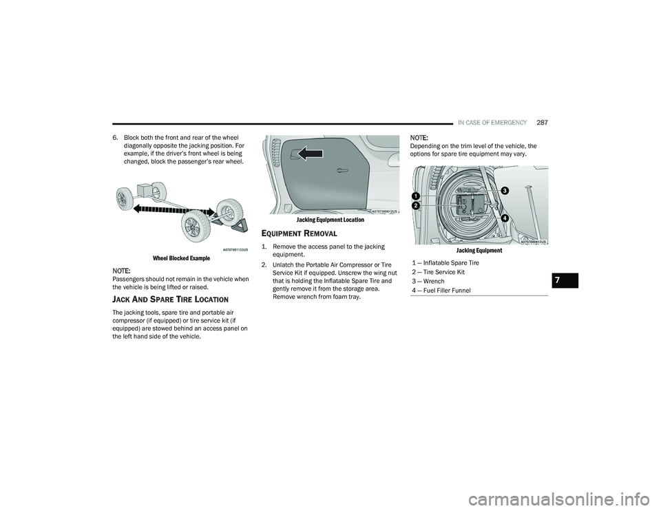
The jacking tools, spare tire and portable air
compressor (if equipped) or tire service kit (if
equipped) are stowed behind an access panel on
the left hand side of the vehicle.
Jacking Equipment Location
EQUIPMENT REMOVAL
1. Remove the access panel to the jacking
equipment.
2. Unlatch the Portable Air Compressor or Tire Service Kit if equipped. Unscrew the wing nut
that is holding the Inflatable Spare Tire and
gently remove it from the storage area.
Remove wrench from foam tray.
NOTE:Depending on the trim level of the vehicle, the
options for spare tire equipment may vary.
Jacking Equipment
1 — Inflatable Spare Tire
2 — Tire Service Kit
3 — Wrench
4 — Fuel Filler Funnel
7
22_RUP_OM_EN_USC_t.book Page 287
Page 294 of 384

292IN CASE OF EMERGENCY
13. Stow the jack back in the stowage compartment and place the access panel
back. The stud of the storage area must be
threaded through the lower part of the jack.
Then turn the Jack Screw clockwise to secure
it in place.
NOTE:Stow the foam tray and components in the cargo
area.
Storing The Jack
ROAD TIRE INSTALLATION
Vehicles Equipped With Wheel Covers
1. Mount the road tire on the axle.
2. To ease the installation process for steel wheels with wheel covers, install two lug nuts
on the mounting studs which are on each side
of the valve stem. Install the lug nuts with the
cone shaped end of the nut toward the wheel.
Lightly tighten the lug nuts.
Tire And Wheel Cover Or Center Cap
3. Align the valve notch in the wheel cover with
the valve stem on the wheel. Install the cover
by hand, snapping the cover over the two lug
nuts. Do not use a hammer or excessive force
to install the cover.
4. Install the remaining lug nuts with the cone shaped end of the nut toward the wheel.
Lightly tighten all the lug nuts until the wheel
sits flush onto the hub and there is no play. The
nuts will have to be fully tightened once the
vehicle is lowered. Tightening an improperly
seated wheel under vehicle load can damage
the threads, cause vibration, and undermine
safety.
1 — Jack Screw
2 — Jack
3 — Stud
1 — Valve Stem
2 — Valve Notch
3 — Road Tire
4 — Wheel Cover
5 — Wheel Lug Nut
WARNING!
To avoid the risk of forcing the vehicle off the
jack, do not tighten the wheel nuts fully until the
vehicle has been lowered. Failure to follow this
warning may result in serious injury.
22_RUP_OM_EN_USC_t.book Page 292