Page 57 of 256

55
Instrument Panel Power Outlet
NOTE:
Do not connect devices, with a power rating
higher than 180 W, to the outlet. Do not use
power adapters that do not fit the outlet as this
may damage it.
Luggage Compartment Power Outlet
There is an additional power outlet located on the
left side of the luggage compartment. It will only
operate when the ignition is in the ON/RUN
position.Luggage Compartment Power Outlet
NOTE:
Do not connect devices with powers higher than
150 W to the socket. Do not damage the outlet by
using unsuitable adapters.
115 Volt Power Inverter — If Equipped
The power inverter is located inside of the center
console. It can be used for small battery-powered
electrical appliances with powers up to 150 W
(e.g. cameras, video camera, tablets, razors,
etc.).
NOTE:
Do not connect devices with powers higher than
150 W to the socket. Do not damage the socket
by using unsuitable adapters.
Power Inverter
CIGAR LIGHTER AND ASH TRAY —
I
F EQUIPPED
If equipped, the cigar lighter is located on the
bottom of the center stack, in front of the
cupholders.
To activate the cigar lighter, push in and wait a
few seconds. Once the cigar lighter has returned
to its original position, it is ready for use.
NOTE:
Always ensure the cigar lighter is turned off when
not in use.
1 — Cigar Lighter
If equipped, the ash tray is a removable plastic
container located inside the cupholder.
WIRELESS CHARGING PAD — IF
E
QUIPPED
Wireless Charging Pad
Your vehicle may be equipped with a 15 W (3 A)
Qi wireless charging pad located inside of the
center console. This charging pad is designed to
wirelessly charge your Qi enabled mobile phone.
22_GU_OM_EN_USC_t.book Page 55
Page 58 of 256

GETTING TO KNOW YOUR VEHICLE
56
Qi is a standard that uses magnetic induction to
transfer power to your mobile device.
Your mobile phone must be designed for Qi
wireless charging.
NOTE:
Do not place the key fob or any other type of
metal/magnetized object inside the mobile
phone housing or near the wireless charging
pad.
Be sure to place the mobile device correctly
(display facing upward) on the wireless
charging pad.
The ignition must be in the ON/RUN position in
order for the phone to charge.
To avoid interference with the key fob search,
the wireless charging pad will stop charging
when any door is opened.
The following messages will display in the radio
system:
“Your phone is being charged” — The phone
has begun to charge.
“Phone Fully Charged” — The phone has
completed charging its battery.
“Foreign Object Detected” — The phone is not
enabled for wireless charging or an object that
is not permitted has been placed on the
wireless charging pad.
“Unavailable System” — There is a malfunction
with the wireless charging pad.
The driver can deactivate these messages
through the radio system. Refer to the
Information and Entertainment System Owner’s
Manual Supplement for further information.
POWER WINDOWS
POWER WINDOW CONTROLS
The power window switches work with the ignition
in the ACC or ON/RUN position and for three
minutes after the ignition has been placed in the
OFF position. When one of the front doors is
opened, this operation is disabled.
The window controls on the driver's door control
all the door windows.
Power Window Switches The passenger door windows can also be
operated by using the single window controls on
the passenger door trim panel.
To open the window part way (manually), push
the window switch down briefly and release. Push
past the detent to activate “continuous
automatic” operation.
If the button is pushed again, the window will stop
in the desired position.
Pull the window switch to the first detent to move
the window upward. Pull the window switch to the
second detent, and the window will go up
automatically.
To close the window, pull the window switch up.
To stop the window during Auto-Up operation,
push or pull the window switch again.
CAUTION!
The key fob should not be placed on the
charging pad or within 6 inches (15 cm) of it.
Doing so can cause excessive heat buildup
and damage to the fob. Placing the fob in
close proximity of the charging pad blocks the
fob from being detected by the vehicle and
prevents the vehicle from starting.
1 — Front Left Window Switch
2 — Front Right Window Switch
3 — Rear Right Window Switch
4 — Window Lockout Switch
5 — Rear Left Window Switch
WARNING!
Never leave children unattended in a vehicle,
and do not let children play with power
windows. Do not leave the key fob in or near
the vehicle, or in a location accessible to
children. Occupants, particularly unattended
children, can become entrapped by the
windows while operating the power window
switches. Such entrapment may result in
serious injury or death.
22_GU_OM_EN_USC_t.book Page 56
Page 59 of 256

57
AUTO-UP FEATURE WITH ANTI-PINCH
P
ROTECTION
The vehicle is equipped with an anti-pinch safety
device for closing the windows.
If the safety system senses any obstacle while the
window is closing, it will stop the window’s
movement and reverse it, depending on its
position.
This device is also useful if the windows are
activated accidentally by children inside the
vehicle.
The anti-pinch safety function is activated both
during the manual and the automatic operation
of the window.
When the anti-pinch system is activated, the
window closing is immediately interrupted. Then
the window closing is automatically reversed and
the window lowers by about 8 inches (20 cm) in
relation to the first stop position. The window
cannot be operated during this time.
NOTE:
In the event of an error, or if the anti-pinch protec -
tion is activated three consecutive times, the
automatic closing operation of the window will be
deactivated. In order to restore the correct opera -
tion of the system, the window must be lowered.
POWER WINDOW SYSTEM INITIALIZATION
If power supply is interrupted, the electric window
automatic operation must be reinitialized.
To perform the initialization procedure, which
must be done on each door with the doors closed,
manually fully close the window to be initialized.
WIND BUFFETING
Wind buffeting can be described as the
perception of pressure on the ears or a
helicopter-type sound in the ears. Your vehicle
may exhibit wind buffeting with the windows
down, or the sunroof (if equipped) in certain open
or partially open positions. This is a normal
occurrence and can be minimized. If the buffeting
occurs with the rear windows open, open the front
and rear windows together to minimize the
buffeting. If the buffeting occurs with the sunroof
open, adjust the sunroof opening to minimize the
buffeting or open any window.
POWER SUNROOF — IF
EQUIPPED
POWER SUNROOF
The power sunroof consists of a single glass
panel and is fitted with a power sunshade the full
length of the panel.
Operation of the sunroof is only possible with the
ignition in the ACC or ON/RUN position
Ú
page 22. Sunroof And Power Shade Buttons
The sunroof has three preset positions:
Fully closed
Comfort (intermediate opening)
Fully open
NOTE:
You cannot have the sunshade closed when the
sunroof is open. 1 — Power Shade Open/Close
2 — Sunroof Open/Close Button
3 — Vent Open/Close
22_GU_OM_EN_USC_t.book Page 57
Page 60 of 256

GETTING TO KNOW YOUR VEHICLE
58
OPENING AND CLOSING THE SUNROOF
To open the sunroof’s front panel, push the
open/close button toward the rear of the vehicle
to open to the comfort position (half way).
Pushing the button a second time will open to the
fully open position.
To close the sunroof, push the open/close button
toward the front of the vehicle. The roof will close
completely.
The automatic motion can be interrupted in any
position by pushing the open/close button again.
VENTING SUNROOF
To bring the roof into vent position, push and
release the vent button.
This type of vent opening can be activated
regardless of the position of the sunroof. When
starting with the roof in the closed position,
pushing the vent button automatically causes the
sunroof to open to the vent position. If the roof is
already open, the button must be held until the
roof reaches the vent-opening position.
Pushing the vent button again during automatic
movement of the roof will stop it.
SUNSHADE OPERATION
The sunshade is power operated.
Push the Power Shade open/close button toward
the rear of the vehicle to open the sun shade.
Push the Power Shade open/close button toward
the front of the vehicle to close the sun shade.
The automatic motion can be interrupted in any
position by pushing the Power Shade open/close
button again.
PINCH PROTECT FEATURE
The sunroof has an anti-pinch safety system
capable of detecting the presence of an obstacle
during the closing movement. If an obstacle is
detected, the system intervenes and the
movement of the sunroof is immediately reversed.
RE-INITIALIZATION PROCEDURE
Automatic operation of the sunroof must be
re-initialized in case of faulty sunroof operation. It
may also be necessary to initialize the sunroof
after the vehicle’s battery has been disconnected
and then reconnected.
NOTE:
The anti-pinch safety device is deactivated during
the re-initialization procedure.
Proceed as follows:
1. With the ignition in the ON/RUN position, make sure the sunroof glass is fully closed
(sunshade open).
2. Open the driver’s side door, and place the ignition in the OFF position.
3. Within five seconds, place the ignition in the ACC or ON/RUN position.
4. Within 10 seconds, push and hold the sunroof close switch (forward). After
8 -10 seconds of holding the switch, the
re-initialization process will begin. Continue
to hold the switch while the sunroof motor
cycles, and the sunshade will fully close.
5. Once the sunroof glass and the power sunshade have stopped motion, release the
sunroof close switch, then push and hold it
again within five seconds. Continue to hold
the switch while the sunshade fully opens,
the sunroof glass fully opens, followed by the
glass fully closing then the sunshade fully
closing.
6. Release the switch once all of the operations stop. Re-initialization of the sunroof motors is
now complete.
WARNING!
Never leave children unattended in a vehicle,
or with access to an unlocked vehicle. Never
leave the key fob in or near the vehicle, or in
a location accessible to children. Do not
leave the Keyless Push Button Ignition in the
ON/RUN position. Occupants, particularly
unattended children, can become entrapped
by the power sunroof while operating the
power sunroof switch. Such entrapment may
result in serious injury or death.
In a collision, there is a greater risk of being
thrown from a vehicle with an open sunroof.
You could also be seriously injured or killed.
Always fasten your seat belt properly and
make sure all passengers are also properly
secured.
Do not allow small children to operate the
sunroof. Never allow your fingers, other body
parts, or any object, to project through the
sunroof opening. Injury may result.
CAUTION!
Do not open the sun roof if a roof rack or
crossbars are fitted. Do not open the sun roof
if there is snow or ice on it: you may damage it.
22_GU_OM_EN_USC_t.book Page 58
Page 61 of 256

59
NOTE:
If the switch is released prior to full completion of
the operations described, the entire re-initializa-
tion procedure must be repeated from step 1.
7. Confirm express operations for the sunroof glass and sunshade are functional for
opening and closing operations.
SUNROOF MAINTENANCE
Use only a non-abrasive cleaner and a soft cloth
to clean the glass panel. Periodically check for
and clear out any debris that may have collected
in the tracks.
HOOD
OPENING THE HOOD
To open the hood, two latches must be released.
1. Pull the release lever located underneath the driver’s side of the instrument panel.
Hood Release Lever
2. Lift the hood slightly. Move the underhood latch from right to left to release the hood. Hood Latch Location
3. Raise the hood completely. The operation is assisted by the addition of two gas props
which hold it in the open position.
NOTE:
Do not tamper with the props and assist the
hood while lifting it.
Use both hands to lift the hood. Before lifting,
check that the windshield wiper arms are not
raised from the windshield or in operation.
Also, ensure that the vehicle is stationary and
that the Electric Park Brake is engaged.
CLOSING THE HOOD
To close, lower the hood to approximately
16 inches (40 cm) from the engine compartment
then let it drop. Make sure that the hood is
completely closed and fully latched.
NOTE:
Since the hood is equipped with a double locking
system, one for each side, you must check that it
is closed on each side.
POWER LIFTGATE
Unlocking of the liftgate is electrically operated
and is deactivated when the vehicle is in motion.
If anything obstructs the power liftgate while it is
closing or opening, the liftgate will automatically
reverse to the closed or open position, provided it
meets sufficient resistance.
OPENING
The liftgate may be released in several ways:
Pressing the liftgate release button on the key
fob twice within five seconds
Pushing the external liftgate release switch
(when the liftgate is unlocked)
Lifting the interior liftgate release button on
the driver’s door panel trim
WARNING!
Be sure the hood is fully latched before driving
your vehicle. If the hood is not fully latched, it
could open when the vehicle is in motion and
block your vision. Failure to follow this warning
could result in serious injury or death.
22_GU_OM_EN_USC_t.book Page 59
Page 62 of 256

GETTING TO KNOW YOUR VEHICLE
60
External Liftgate Release SwitchInterior Liftgate Release
The turn signal indicators will blink and the
interior lights will turn on when the liftgate is
opened. They turn off automatically when the
liftgate is closed.
The lights turn off automatically after a few
minutes if the liftgate is left open.
A signal will chime while the liftgate is opening or
closing.
NOTE:
You can stop the liftgate from moving by pushing
the interior liftgate release button again.
Liftgate Emergency Opening
There is a panel on the luggage compartment
interior trim, next to the liftgate lock, accessible
by folding down the rear seat backrest, which
allows access to the manual lock release.
Manual Lock Release Location
Pull to release the lock.
Manual Lock Release Cord The liftgate can now be opened manually.CLOSING
It is possible to close the liftgate by pushing:
The power liftgate switch.
The power lock switch located on the liftgate
(all the doors, including the liftgate, will be
locked).
The liftgate button on the key fob twice.
The power liftgate switch on the liftgate.
The power liftgate switch on the driver’s door
panel trim and hold until the operation is
complete.
Power Liftgate/Lock Switches
NOTE:
It is possible to stop the liftgate from moving with
any of the Power Liftgate switches.
1 — Interior Liftgate Release Switch
1 — Power Liftgate Switch
2 — Power Door Lock Switch
22_GU_OM_EN_USC_t.book Page 60
Page 63 of 256

61
Customizing The Liftgate Opening Height
To avoid difficulties in tight spaces, you can set
the height at which the liftgate opens to.
To customize the liftgate opening position, follow
the steps below:
1. Open the liftgate manually and move it to theposition that you want the liftgate to open to.
2. Press and hold one of the closing buttons for at least five seconds (successful program -
ming is indicated by the turn signals flashing
three times).
The liftgate is now programmed to open to the set
position.
This function can be selected on the radio
system.
To set the liftgate opening height, refer to the
Information and Entertainment System Owner’s
Manual Supplement for further information.
Hands-Free Liftgate — If Equipped
To operate the Hands-Free Liftgate system:
1. If the doors are locked, the system must detect the key fob near the liftgate.
2. If the doors are unlocked, the system does not have to detect the key fob near the lift -
gate.
3. Go to the rear of the vehicle, in the center and about 3 feet (1 m) from the liftgate.
4. Move your foot under the bumper, simulating a kick. When you have completed this move -
ment, withdraw your leg. To activate the lift -
gate, both sensors must detect your leg. Hands Free Liftgate Activation Zone
If it is closed, the Hands-Free Liftgate unlocks and
opens completely, and with another movement of
the foot, it stops. A further movement of the foot
reverses the direction and closes the liftgate
completely, if you do not stop it again.
If it is open, with a movement of the foot, the
Hands-Free Liftgate closes completely, and with
another movement of the foot, it stops. If the
liftgate is stopped, another movement of the foot
will reverse the direction and open it completely.
NOTE:
To conserve the battery charge, avoid performing
this operation repeatedly with the engine off.
You can activate/deactivate the Hands-Free
Liftgate on the radio system by pushing the MENU
button to select the Main menu, and selecting the
following items:
1. Settings
2. Doors And Locks
3. Automatic Liftgate Opening
LIFTGATE INITIALIZATION
NOTE:
Automatic operation of the liftgate must be initial -
ized again in case of faulty liftgate operation.
Proceed as follows:
1. Close all the doors and the liftgate.
2. Push the lock button on the key fob.
3. Push the unlock button on the key fob.
WARNING!
Driving with the liftgate open can allow
poisonous exhaust gases into your vehicle.
You and your passengers could be injured by
these fumes. Keep the liftgate closed when
you are operating the vehicle.
If you are required to drive with the liftgate
open, make sure that all windows are closed,
and the climate control blower switch is set
at high speed. Do not use the recirculation
mode.
During power operation, personal injury or
cargo damage may occur. Ensure the liftgate
travel path is clear. Make sure the liftgate is
closed and latched before driving away.
CAUTION!
The Hands-Free Liftgate can be turned off
manually in the radio system to avoid uninten -
tional activation. For further information refer
to the Information and Entertainment System
Owner’s Manual Supplement.
22_GU_OM_EN_USC_t.book Page 61
Page 64 of 256

GETTING TO KNOW YOUR VEHICLE
62
CARGO AREA FEATURES
Retractable Cargo Area Cover
The Retractable Cargo Area Cover can be rolled
up and removed.
To Use The Cargo Area Cover:
1. From the rolled up (retracted) position, holdthe handle and pull the cover outward toward
the rear of the vehicle.
2. Then assist the cover pins into the slots located just inside the liftgate opening.
Retractable Cargo Area Cover
Removing The Cover:
1. Retract the cover by pulling the handle slightly rearward to release the cover pins.
2. Guide the cover forward until it is fully retracted. 3. Pull the two cover hooks (one on each side)
towards the inside of the cargo area. Then lift
the cover up and remove it.
Cover Attached
Rear Cargo Anchors
The cargo area floor may be equipped with fixed
or mobile anchoring loops that allow you to
anchor and secure luggage safely. The fixed anchor loops are located in the four
corners of the cargo floor.
Anchor Loops
Cargo Area Adjustable Rail — If Equipped
The mobile loops (if equipped), slide on two
guides secured to the cargo area floor.
To position a loop, push down the center button
while sliding the loop along the guide to the
desired position. Release the button and move
the loop slightly to the next fixed position in the
notches on the guide.
Adjustable Anchor Loop — If Equipped
1 — Handle
2 — Cover Pins3 — Cover Hook
WARNING!
In a collision, a loose cargo cover in the
vehicle could cause injury. It could fly around
in a sudden stop and strike someone in the
vehicle. Do not store the cargo cover on the
cargo floor or in the passenger compartment.
Remove the cover from the vehicle when
taken from its mounting. Do not store it in the
vehicle.
22_GU_OM_EN_USC_t.book Page 62
 1
1 2
2 3
3 4
4 5
5 6
6 7
7 8
8 9
9 10
10 11
11 12
12 13
13 14
14 15
15 16
16 17
17 18
18 19
19 20
20 21
21 22
22 23
23 24
24 25
25 26
26 27
27 28
28 29
29 30
30 31
31 32
32 33
33 34
34 35
35 36
36 37
37 38
38 39
39 40
40 41
41 42
42 43
43 44
44 45
45 46
46 47
47 48
48 49
49 50
50 51
51 52
52 53
53 54
54 55
55 56
56 57
57 58
58 59
59 60
60 61
61 62
62 63
63 64
64 65
65 66
66 67
67 68
68 69
69 70
70 71
71 72
72 73
73 74
74 75
75 76
76 77
77 78
78 79
79 80
80 81
81 82
82 83
83 84
84 85
85 86
86 87
87 88
88 89
89 90
90 91
91 92
92 93
93 94
94 95
95 96
96 97
97 98
98 99
99 100
100 101
101 102
102 103
103 104
104 105
105 106
106 107
107 108
108 109
109 110
110 111
111 112
112 113
113 114
114 115
115 116
116 117
117 118
118 119
119 120
120 121
121 122
122 123
123 124
124 125
125 126
126 127
127 128
128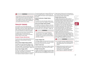 129
129 130
130 131
131 132
132 133
133 134
134 135
135 136
136 137
137 138
138 139
139 140
140 141
141 142
142 143
143 144
144 145
145 146
146 147
147 148
148 149
149 150
150 151
151 152
152 153
153 154
154 155
155 156
156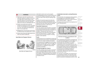 157
157 158
158 159
159 160
160 161
161 162
162 163
163 164
164 165
165 166
166 167
167 168
168 169
169 170
170 171
171 172
172 173
173 174
174 175
175 176
176 177
177 178
178 179
179 180
180 181
181 182
182 183
183 184
184 185
185 186
186 187
187 188
188 189
189 190
190 191
191 192
192 193
193 194
194 195
195 196
196 197
197 198
198 199
199 200
200 201
201 202
202 203
203 204
204 205
205 206
206 207
207 208
208 209
209 210
210 211
211 212
212 213
213 214
214 215
215 216
216 217
217 218
218 219
219 220
220 221
221 222
222 223
223 224
224 225
225 226
226 227
227 228
228 229
229 230
230 231
231 232
232 233
233 234
234 235
235 236
236 237
237 238
238 239
239 240
240 241
241 242
242 243
243 244
244 245
245 246
246 247
247 248
248 249
249 250
250 251
251 252
252 253
253 254
254 255
255