Page 57 of 94

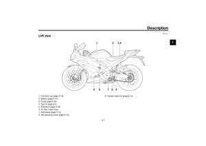
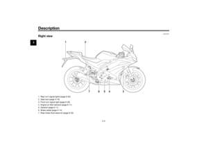
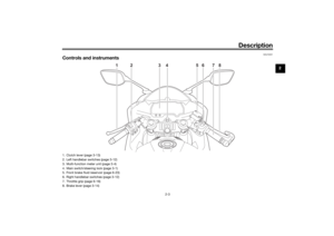
Periodic maintenance an d a djustment
6-13
6
10. Refill with the specified amount of
the recommended engine oil, and
then install and tighten the oil filler
cap.
NOTICE
ECA11621
In or der to prevent clutch slip-
pa ge (since the en gine oil also
lu bricates the clutch), do not
mix any chemical additives. Do
not use oils with a diesel speci-
fication of “CD” or oils of a hi gh-
er quality than specifie d. In
a ddition, do not use oils lab eled
“ENERGY CONSERVING II” or
hi gher.
Make sure that no forei gn mate-
rial enters the crankcase.
11. Start the engine, and then let it idle for several minutes while checking
it for oil leakage. If oil is leaking,
immediately turn the engine off
and check for the cause.
12. Turn the engine off, and then check the oil level and correct it if
necessary.
EAU85450
Why Yamalu beYAMALUBE oil is a Genuine YAMAHA
Part born of the engineers’ passion
and belief that engine oil is an impor-
tant liquid engine component. We form
teams of specialists in the fields of me-
chanical engineering, chemistry, elec-
tronics and track testing, and have
them develop the engine together with
the oil it will use. Yamalube oils take full
advantage of the base oil’s qualities
and blend in the ideal balance of addi-
tives to make sure the final oil clears
our performance standards. Thus,
Yamalube mineral, semisynthetic and
synthetic oils have their own distinct
characters and value. Yamaha’s expe-
rience gained over many years of re-
search and development into oil since
the 1960’s helps make Yamalube the
best choice for your Yamaha engine.
Recommen ded en gine oil:
See page 8-1.
Oil quantity: Oil change:
0.85 L (0.90 US qt, 0.75 Imp.qt)
With oil filter removal: 0.95 L (1.00 US qt, 0.84 Imp.qt)
UB5GE2E0.book Page 13 Thursday, July 30, 2020 3:08 PM
Page 58 of 94

Periodic maintenance an d a djustment
6-14
6
EAUS1203
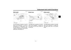
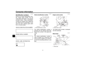
CoolantThe coolant level should be checked
regularly. In addition, the coolant must
be changed at the intervals specified in
the periodic maintenance chart.TIPIf genuine Yamaha coolant is not avail-
able, use an ethylene glycol antifreeze
containing corrosion inhibitors for alu-
minum engines and mix with distilled
water at a 1:1 ratio.
EAUE3460
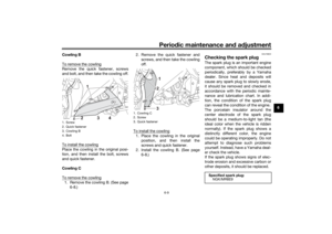
To check the coolant level
1. Place the vehicle on a level sur- face.
2. Remove cowling C of left side. (See page 6-8.)
3. Hold the vehicle in an upright po- sition.
TIPThe coolant level must be
checked on a cold engine since
the level varies with engine tem-
perature.
Make sure that the vehicle is posi-
tioned straight up when checking
the coolant level. A slight tilt to the
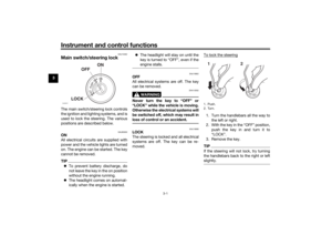
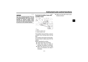
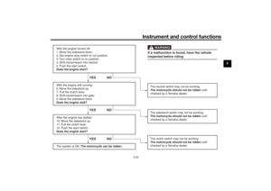
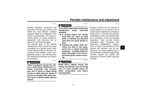
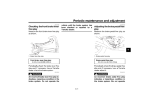
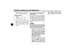
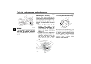
side can result in a false reading.4. Check the coolant level in the
coolant reservoir.TIPThe coolant should be between the
minimum and maximum level marks.
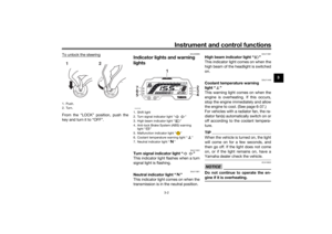
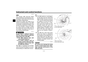
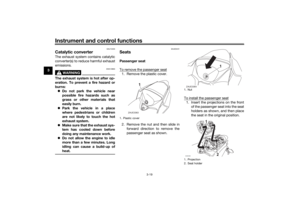
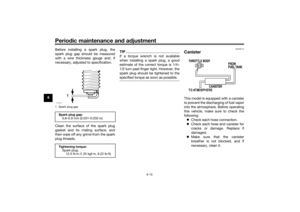
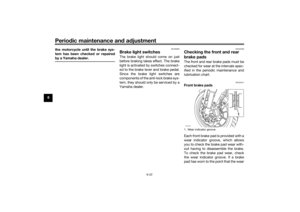
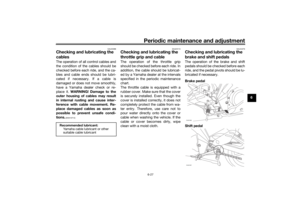
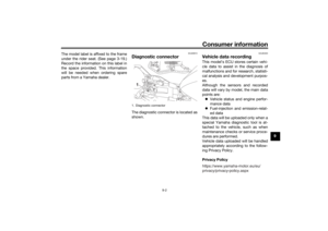
5. If the coolant is at or below theminimum level mark, remove the
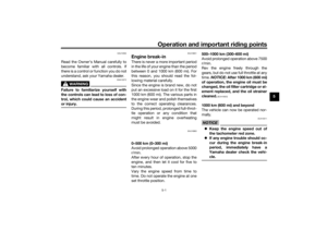
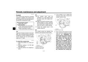
coolant reservoir cap.
6. Add coolant to the maximum level mark, and then install the coolant
reservoir cap. WARNING! Re-
move only the coolant reservoir
cap. Never attempt to remove
the ra diator cap when the en-
g ine is hot.
[EWA15162]
NOTICE: If
coolant is not availa ble, use dis-
tille d water or soft tap water in-
stead . Do not use har d water or
salt water since it is harmful to
the en gine. If water has been
use d instead of coolant, replace
it with coolant as soon as possi-
b le, otherwise the coolin g sys-
Recommen ded coolant:
YAMALUBE coolant
Coolant quantity: Coolant reservoir (max level mark):0.15 L (0.16 US qt, 0.13 Imp.qt)
Radiator (including all routes): 0.49 L (0.52 US qt, 0.43 Imp.qt)
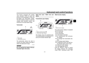
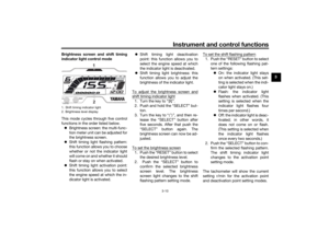
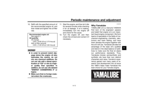
1. Coolant reservoir
2. Maximum level mark
3. Minimum level mark
1
2
3
FULL
LOW
ZAUE3384
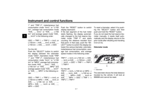
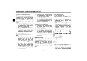
1. Coolant reservoir cap
1ZAUE3385
UB5GE2E0.book Page 14 Thursday, July 30, 2020 3:08 PM
Page 59 of 94

Periodic maintenance an d a djustment
6-15
6
tem will not
be protecte d
a g ainst frost an d corrosion. If
water has been a dded to the
coolant, have a Yamaha dealer
check the antifreeze content of
the coolant as soon as possi ble,
otherwise the effectiveness of
the coolant will be re duce d.
[ECA10473]
7. Install the cowling.
EAU33032
Chan gin g the coolant
The coolant must be changed at the in-
tervals specified in the periodic main-
tenance and lubrication chart. Have a
Yamaha dealer change the coolant.
WARNING! Never attempt to remove the ra diator cap when the en gine is
hot.
[EWA10382] EAUM2391
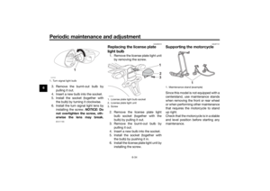
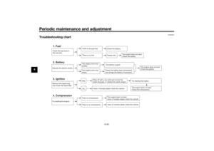
Replacin
g the air filter ele-
ment an d cleanin g the check
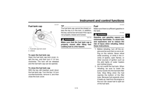
hoseThe air filter element should be re-
placed at the intervals specified in the
periodic maintenance and lubrication
chart. Have a Yamaha dealer replace
the air filter element more frequently if
you are riding in unusually wet or dusty
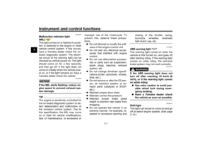
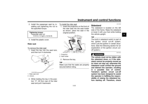
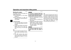
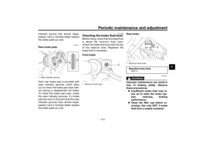
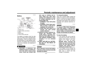
areas. In addition, the air filter check
hose must be frequently checked and
cleaned if necessary.
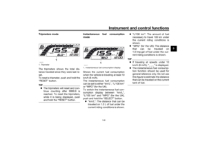
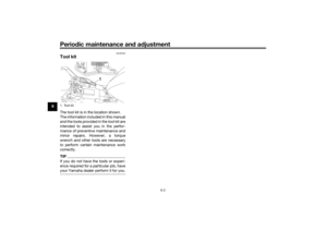
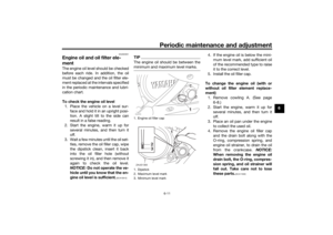
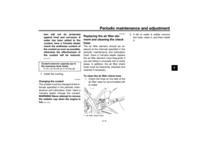
To clean the air filter check hose
1. Check the hose on the side of the air filter case for accumulated dirt
or water. 2. If dirt or water is visible, remove
the hose, clean it, and then install
it.
Coolant reservoir capacity (up to
the maximum level mark):0.15 L (0.16 US qt, 0.13 Imp.qt)
1. Air filter check hoseZAUM1594
UB5GE2E0.book Page 15 Thursday, July 30, 2020 3:08 PM
Page 60 of 94

Periodic maintenance an d a djustment
6-16
6
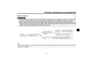
EAU34302
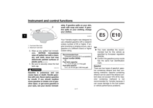
A djustin g the eng ine idlin g
spee dThe engine idling speed must be
checked and, if necessary, adjusted as
follows at the intervals specified in the
periodic maintenance and lubrication
chart.
The engine should be warm before
making this adjustment.
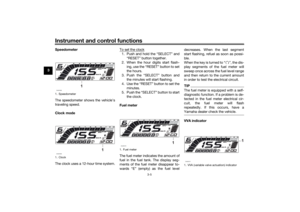
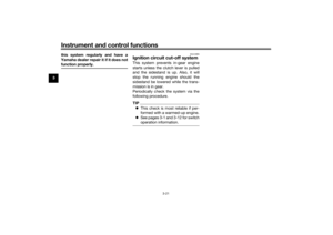
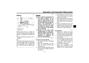
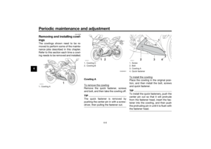
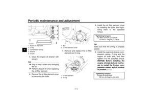
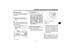
Check the engine idling speed and, if
necessary, adjust it to specification by
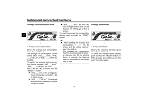
turning the idle adjusting screw. To in-
crease the engine idling speed, turn
the screw in direction (a). To decrease
the engine idling speed, turn the screw
in direction (b).
TIPIf the specified idling speed cannot be
obtained as described above, have a
Yamaha dealer make the adjustment.
EAU48434
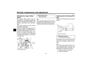
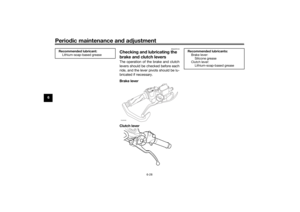
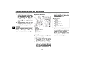
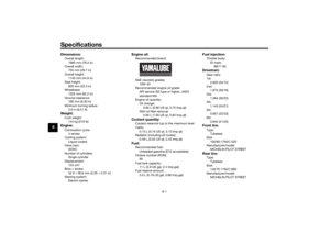
A djustin g the throttle grip free
playMeasure the throttle grip free play as
shown.
Periodically check the throttle grip free
play and, if necessary, adjust it as fol-
lows.TIPThe engine idling speed must be cor-
rectly adjusted before checking and
adjusting the throttle grip free play.1. Slide the rubber cover back.
2. Loosen the locknut.
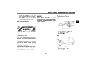
1. Idle adjusting screwZAUE3388
(a)
(b)
1
En gine i dlin g spee d:
1250–1550 r/min
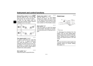
1. Throttle grip free playThrottle grip free play:
3.0–5.0 mm (0.12–0.20 in)ZAUM1595
1
UB5GE2E0.book Page 16 Thursday, July 30, 2020 3:08 PM
Page 61 of 94
. To decrease the throt-
tle grip free play, turn the adjusting
nut in")
Periodic maintenance an d a djustment
6-17
6
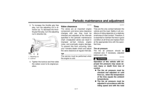
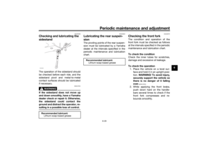
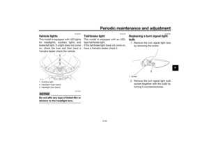
3. To increase the throttle grip free
play, turn the adjusting nut in di-
rection (a). To decrease the throt-
tle grip free play, turn the adjusting
nut in direction (b).
4. Tighten the locknut and then slide the rubber cover to its original po-
sition.
EAU21403
Valve clearanceThe valves are an important engine
component, and since valve clearance
changes with use, they must be
checked and adjusted at the intervals
specified in the periodic maintenance
chart. Unadjusted valves can result in
improper air-fuel mixture, engine
noise, and eventually engine damage.
To prevent this from occurring, have
your Yamaha dealer check and adjust
the valve clearance at regular intervals.TIPThis service must be performed when
the engine is cold.
EAU77621
TiresTires are the only contact between the
vehicle and the road. Safety in all con-
ditions of riding depends on a relatively
small area of road contact. Therefore, it
is essential to maintain the tires in good
condition at all times and replace them
at the appropriate time with the speci-
fied tires.
Tire air pressure
The tire air pressure should be
checked and, if necessary, adjusted
before each ride.
WARNING
EWA10504
Operation of this vehicle with im-
proper tire pressure may cause se-
vere injury or d eath from loss of
control. The tire air pressure must be
checked and a djuste d on col d
tires (i.e., when the temperature
of the tires equals the am bient
temperature).
The tire air pressure must be
a d juste d in accor dance with the
ri din g spee d an d with the total
1. Adjusting nut
2. LocknutZAUM1596
1 2
(a)
(b)
UB5GE2E0.book Page 17 Thursday, July 30, 2020 3:08 PM
Page 62 of 94

Periodic maintenance an d a djustment
6-18
6 wei
ght of ri der, passen ger, car-
g o, an d accessories approve d
for this mo del.
WARNING
EWA10512
Never overloa d your vehicle. Opera-
tion of an overloa ded vehicle coul d
cause an acci dent.
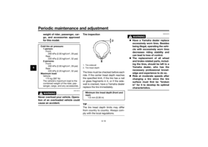
Tire inspection
The tires must be checked before each
ride. If the center tread depth reaches
the specified limit, if the tire has a nail
or glass fragments in it, or if the side-
wall is cracked, have a Yamaha dealer
replace the tire immediately.TIPThe tire tread depth limits may differ
from country to country. Always com-
ply with the local regulations.
WARNING
EWA10472
Have a Yamaha dealer replace
excessively worn tires. Besi des
b ein g ille gal, operatin g the vehi-
cle with excessively worn tires
d ecreases rid ing sta bility an d
can lead to loss of control.
The replacement of all wheel
and b rake-relate d parts, inclu d-
in g the tires, shoul d b e left to a
Yamaha dealer, who has the
necessary professional knowl-
e dge an d experience to do so.
Ride at mo derate speed s after
chan gin g a tire since the tire
surface must first be “ broken
in” for it to develop its optimal
characteristics.
Col d tire air pressure:
1 person: Front:200 kPa (2.00 kgf/cm², 29 psi)
Rear: 220 kPa (2.20 kgf/cm², 32 psi)
2 persons:
Front:200 kPa (2.00 kgf/cm², 29 psi)
Rear:
220 kPa (2.20 kgf/cm², 32 psi)
Maximum loa d:
Vehicle:
175 kg (387 lb)
The vehicle’s maximum load is the
combined weight of the rider, pas-
senger, cargo, and any accessories.
1. Tire sidewall
2. Tire tread depthMinimum tire trea d d epth (front an d
rear): 1.6 mm (0.06 in)
UB5GE2E0.book Page 18 Thursday, July 30, 2020 3:08 PM
Page 63 of 94

Periodic maintenance an d a djustment
6-19
6
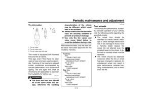
Tire information
This model is equipped with tubeless
tires and tire air valves.
Tires age, even if they have not been
used or have only been used occasion-
ally. Cracking of the tread and sidewall
rubber, sometimes accompanied by
carcass deformation, is an evidence of
ageing. Old and aged tires shall be
checked by tire specialists to ascertain
their suitability for further use.
WARNING
EWA16101
The front an d rear tires shoul d
b e of the same make an d d e-
si gn, otherwise the han dlin g characteristics of the vehicle
may
be different, which coul d
lea d to an acci dent.
Always make sure that the valve
caps are securely installe d to
prevent air pressure leaka ge.
Use only the tire valves an d
valve cores liste d below to
avoi d tire d eflation during a ride.
After extensive tests, only the tires list-
ed below have been approved for this
model by Yamaha.
EAU21963
Cast wheelsTo maximize the performance, durabil-
ity, and safe operation of your vehicle,
note the following points regarding the
specified wheels.
The wheel rims should be
checked for cracks, bends, warp-
age or other damage before each
ride. If any damage is found, have
a Yamaha dealer replace the
wheel. Do not attempt even the
smallest repair to the wheel. A de-
formed or cracked wheel must be
replaced.
The wheel should be balanced
whenever either the tire or wheel
has been changed or replaced. An
unbalanced wheel can result in
poor performance, adverse han-
dling characteristics, and a short-
ened tire life.
1. Tire air valve
2. Tire air valve core
3. Tire air valve cap with seal
Front tire:
Size:100/80-17M/C 52S
Manufacturer/model: MICHELIN PILOT STREET
Tire air valve:
TR412
Valve core: V3002 (original)
Rear tire: Size:140/70-17M/C 66S
Manufacturer/model: MICHELIN PILOT STREET
Tire air valve:
TR412
Valve core: V3002 (original)
UB5GE2E0.book Page 19 Thursday, July 30, 2020 3:08 PM
Page 64 of 94

Periodic maintenance an d a djustment
6-20
6
EAU33893
A djustin g the clutch lever free
playMeasure the clutch lever free play as
shown.
Periodically check the clutch lever free
play and, if necessary, adjust it as fol-
lows.
To increase the clutch lever free play,
turn the clutch lever free play adjusting
bolt at the clutch lever in direction (a).
To decrease the clutch lever free play,
turn the adjusting bolt in direction (b).
TIPIf the specified clutch lever free play
cannot be obtained as described
above, proceed as follows.1. Fully turn the adjusting bolt at the
clutch lever in direction (a) to loos-
en the clutch cable.
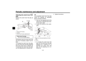
2. Loosen the locknut at the crank- case.
3. To increase the clutch lever free play, turn the clutch lever free play
adjusting nut in direction (a). To
decrease the clutch lever free
play, turn the adjusting nut in di-
rection (b). 4. Tighten the locknut.
1. Clutch lever free play
2. Locknut
3. Clutch lever free play adjusting boltClutch lever free play:
10.0–15.0 mm (0.39–0.59 in)ZAUM1597
)
)
3
2
1 (a
(b
1. Clutch lever free play adjusting nut (crank- case)
2. LocknutZAUM1598
2
(a)
(b) 1
UB5GE2E0.book Page 20 Thursday, July 30, 2020 3:08 PM