Page 25 of 90

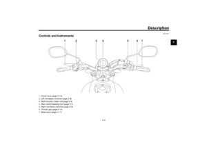
Instrument and control functions
3-10
3
EAU12352
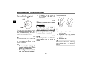
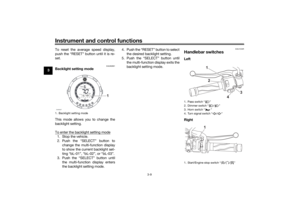
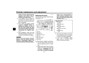
Pass switch “ ”
Press this switch to flash the headlight.TIPWhen the dimmer switch is set
to “ ”, the passing switch has no ef-
fect.
EAU12402
Dimmer switch “ / ”
Set this switch to “ ” for the high
beam and to “ ” for the low beam.
EAU12461
Turn si gnal switch “ / ”
To signal a right-hand turn, push this
switch to “ ”. To signal a left-hand
turn, push this switch to “ ”. When
released, the switch returns to the cen-
ter position. To cancel the turn signal
lights, push the switch in after it has re-
turned to the center position.
EAU12501
Horn switch “ ”
Press this switch to sound the horn.
EAU68271
Start/En gine stop switch “ / / ”
To crank the engine with the starter,
set this switch to “ ”, and then slide
the switch toward “ ”. See page 5-2
for starting instructions prior to starting
the engine.
Set this switch to “ ” to stop the en-
gine in case of an emergency, such as
when the vehicle overturns or when the
throttle cable is stuck.
EAU12823
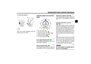
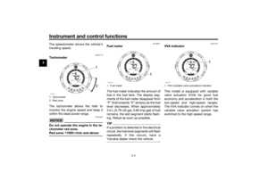
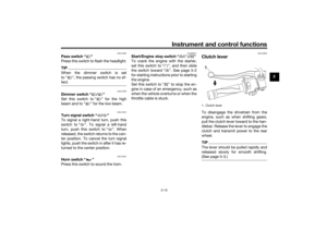
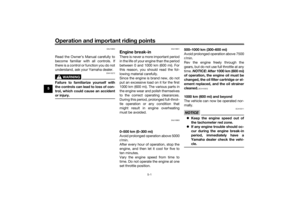
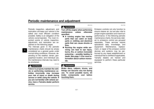
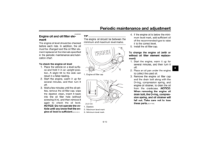
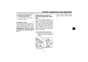
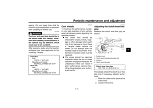
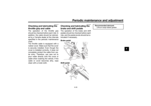
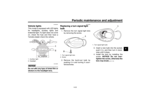
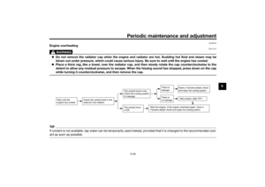
Clutch leverTo disengage the drivetrain from the
engine, such as when shifting gears,
pull the clutch lever toward to the han-
dlebar. Release the lever to engage the
clutch and transmit power to the rear
wheel.TIPThe lever should be pulled rapidly and
released slowly for smooth shifting.
(See page 5-3.)1. Clutch lever1
UBFGE0E0.book Page 10 Friday, April 9, 2021 9:25 AM
Page 26 of 90
Instrument and control functions
3-11
3
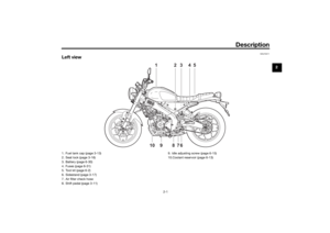
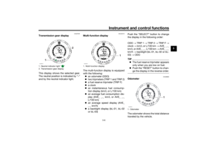
EAU12876
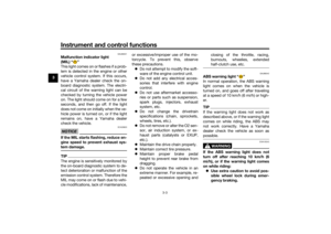
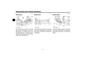
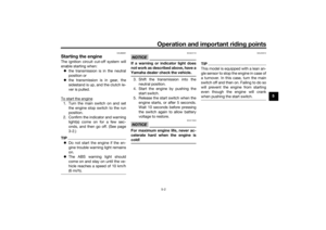
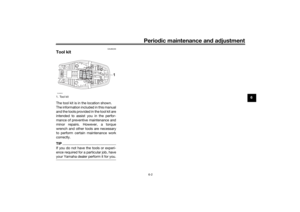
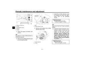
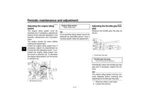
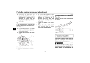
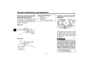
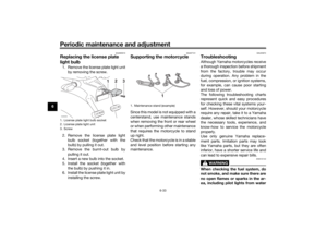
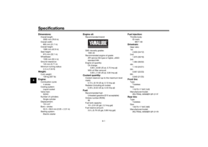
Shift pe dalThe shift pedal is located on the left
side of the motorcycle. To shift the
transmission to a higher gear, move
the shift pedal up. To shift the trans-
mission to a lower gear, move the shift
pedal down. (See page 5-3.)
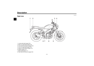
EAU12892
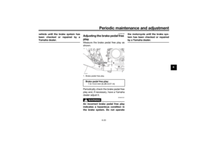
Brake leverThe brake lever is located on the right
side of the handlebar. To apply the
front brake, pull the lever toward the
throttle grip.
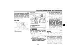
EAU12944
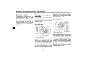
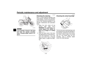
Brake ped alThe brake pedal is located on the right
side of the motorcycle. To apply the
rear brake, press down on the brake
pedal.
1. Shift pedalZAUM2028
1. Brake lever
1
1. Brake pedalZAUM2029
UBFGE0E0.book Page 11 Friday, April 9, 2021 9:25 AM
Page 27 of 90
 features a dual electronic con-
trol system, which acts on the front and
rear brakes independently.
Operate")
Instrument and control functions
3-12
3
EAU63041
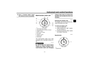
ABSThe Yamaha ABS (Anti-lock Brake
System) features a dual electronic con-
trol system, which acts on the front and
rear brakes independently.
Operate the brakes with ABS as you
would conventional brakes. If the ABS
is activated, a pulsating sensation may
be felt at the brake lever or brake ped-
al. In this situation, continue to apply
the brakes and let the ABS work; do
not “pump” the brakes as this will re-
duce braking effectiveness.
WARNING
EWA16051
Always keep a sufficient d istance
from the vehicle ahea d to match the
ri din g speed even with ABS.
The ABS performs best with
lon g b rakin g d istances.
On certain surfaces, such as
rou gh or g ravel roa ds, the b rak-
in g d istance may be lon ger with
the ABS than without.The ABS is monitored by an ECU,
which will revert the system to conven-
tional braking if a malfunction occurs.
TIP The ABS performs a self-diagnos-
tic test each time the vehicle first
starts off after the key is turned to
“ON” and the vehicle has traveled
at a speed of 10 km/h (6 mi/h) or
higher. During this test, a “click-
ing” noise can be heard from the
hydraulic control unit, and if the
brake lever or brake pedal is even
slightly applied, a vibration can be
felt at the lever and pedal, but
these do not indicate a malfunc-
tion.
This ABS has a test mode which
allows the owner to experience
the pulsation at the brake lever or
brake pedal when the ABS is op-
erating. However, special tools are
required, so please consult your
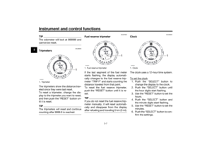
Yamaha dealer.NOTICE
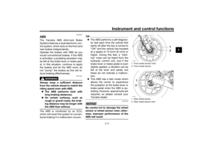
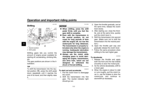
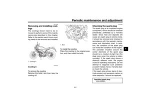
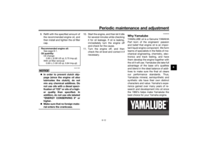
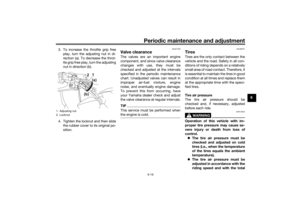
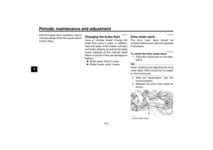
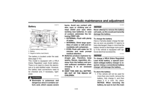
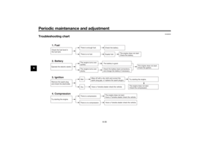
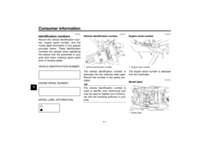
ECA20100
Be careful not to d amage the wheel
sensor or wheel sensor rotor; other-
wise, improper performance of the
ABS will result.
1. Front wheel sensor rotor
2. Front wheel sensor
1. Rear wheel sensor
2. Rear wheel sensor rotorZAUM2030ZAUM2031
UBFGE0E0.book Page 12 Friday, April 9, 2021 9:25 AM
Page 28 of 90

Instrument and control functions
3-13
3
EAU13077
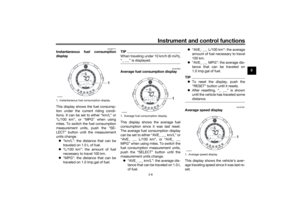
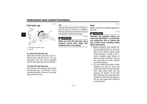
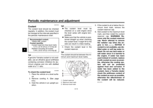
Fuel tank capTo open the fuel tank cap
Open the fuel tank cap lock cover, in-
sert the key, and then turn it 1/4 turn
clockwise. The lock will be released
and the fuel tank cap can be opened.
To close the fuel tank cap
With the key still inserted, push down
the fuel tank cap. Turn the key 1/4 turn
counterclockwise, remove it, and then
close the lock cover.
TIPThe fuel tank cap cannot be closed un-
less the key is in the lock. In addition,
the key cannot be removed if the cap is
not properly closed and locked.
WARNING
EWA11092
Make sure that the fuel tank cap is
properly close d after fillin g fuel.
Leakin g fuel is a fire hazar d.
EAU13222
FuelMake sure there is sufficient gasoline in
the tank.
WARNING
EWA10882
Gasoline an d g asoline vapors are
extremely flamma ble. To avoi d fires
an d explosions an d to re duce the
risk of injury when refuelin g, follow
these instructions.1. Before refueling, turn off the en- gine and be sure that no one is sit-
ting on the vehicle. Never refuel
while smoking, or while in the vi-
cinity of sparks, open flames, or
other sources of ignition such as
the pilot lights of water heaters
and clothes dryers.
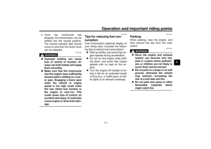
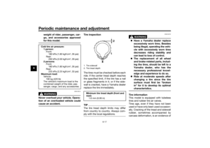
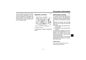
2. Do not overfill the fuel tank. When refueling, be sure to insert the
pump nozzle into the fuel tank filler
hole. Stop filling when the fuel
reaches the bottom of the filler
tube. Because fuel expands when
it heats up, heat from the engine or
the sun can cause fuel to spill out
of the fuel tank.
1. Fuel tank cap lock cover
2. Unlock.
1
2
UBFGE0E0.book Page 13 Friday, April 9, 2021 9:25 AM
Page 29 of 90

Instrument and control functions
3-14
3
3. Wipe up any spilled fuel immedi- ately. NOTICE: Immediately
wipe off spille d fuel with a clean,
d ry, soft cloth, since fuel may
d eteriorate painte d surfaces or
plastic parts.
[ECA10072]
4. Be sure to securely close the fuel tank cap.
WARNING
EWA15152
Gasoline is poisonous an d can cau-
se injury or death. Han dle gasoline
with care. Never siphon gasoline by
mouth. If you shoul d swallow some
g asoline or inhale a lot of gasoline
vapor, or get some g asoline in your
eyes, see your d octor immediately. If g
asoline spills on your skin, wash
with soap an d water. If gasoline
spills on your clothin g, chan ge your
clothes.
EAU86072
Your Yamaha engine was designed to
use unleaded gasoline with a research
octane number of 95 or higher. If en-
gine knocking or pinging occurs, use a
gasoline of a different brand or higher
octane rating.
TIP This mark identifies the recom-
mended fuel for this vehicle as
specified by European regulation
(EN228).
Confirm the gasoline pump nozzle
has the same fuel identification
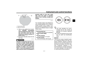
mark.Gasohol
There are two types of gasohol: gaso-
hol containing ethanol and that con-
taining methanol. Gasohol containing
ethanol can be used if the ethanol con-
tent does not exceed 10% (E10). Gas-
ohol containing methanol is not
recommended by Yamaha because it
can cause damage to the fuel system
or vehicle performance problems.
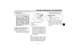
1. Fuel tank filler tube
2. Maximum fuel level
1
2
Recommended fuel:
Unleaded gasoline (E10 acceptable)
Octane num ber (RON):
95
Fuel tank capacity: 10 L (2.6 US gal, 2.2 Imp.gal)
Fuel tank reserve:
3.0 L (0.79 US gal, 0.66 Imp.gal)
E5
E10
UBFGE0E0.book Page 14 Friday, April 9, 2021 9:25 AM
Page 30 of 90
Instrument and control functions
3-15
3
NOTICE
ECA11401
Use only unlea ded g asoline. The use
of lead ed g asoline will cause severe
d amag e to internal en gine parts,
such as the valves an d piston rin gs,
as well as to the exhaust system.
EAU86240
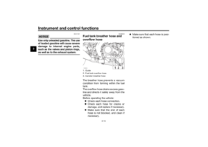
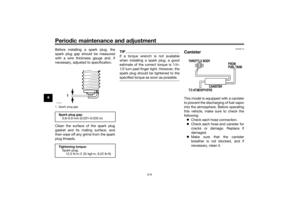
Fuel tank breather hose an d
overflow hoseThe breather hose prevents a vacuum
condition from forming within the fuel
tank.
The overflow hose drains excess gaso-
line and directs it safely away from the
vehicle.
Before operating the vehicle:
Check each hose connection.
Check each hose for cracks or
damage, and replace if necessary.
Make sure that the end of each
hose is not blocked, and clean if
necessary.
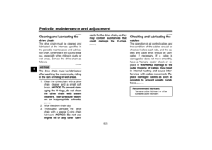
Make sure that each hose is posi-
tioned as shown.1. Guide
2. Fuel tank overflow hose
3. Canister breather hoseZAUM2032
UBFGE0E0.book Page 15 Friday, April 9, 2021 9:25 AM
Page 31 of 90
 to reduce harmful exhaust
emissions.
WARNING
EWA10863
The exhaust system is hot a")
Instrument and control functions
3-16
3
EAU13435
Catalytic converterThe exhaust system contains catalytic
converter(s) to reduce harmful exhaust
emissions.
WARNING
EWA10863
The exhaust system is hot after op-
eration. To prevent a fire hazar d or
b urns:
Do not park the vehicle near
possi ble fire hazar ds such as
g rass or other materials that
easily burn.
Park the vehicle in a place
where pe destrians or chil dren
are not likely to touch the hot
exhaust system.
Make sure that the exhaust sys-
tem has coole d down before
d oin g any maintenance work.
Do not allow the en gine to i dle
more than a few minutes. Lon g
i d lin g can cause a buil d-up of
heat.
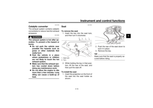
EAU13941
SeatTo remove the seat 1. Insert the key into the seat lock, and then turn it clockwise.
2. While holding the key in that posi- tion, lift the rear of the seat, and
then pull the seat off.
To install the seat 1. Insert the projection on the front of the seat into the seat holder as
shown. 2. Push the rear of the seat down to
lock it in place.
3. Remove the key.
TIPMake sure that the seat is properly se-
cured before riding.
1. Seat lock
2. Turn.
2
1
UBFGE0E0.book Page 16 Friday, April 9, 2021 9:25 AM
Page 32 of 90

2. Hook the he")
Instrument and control functions
3-17
3
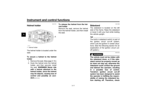
EAU14314
Helmet hol derThe helmet holder is located under the
seat.
To secure a helmet to the helmet
hol der
1. Remove the seat. (See page 3-16.)
2. Hook the helmet onto the helmet holder, and then securely install
the seat. WARNING! Never ri de
with a helmet attached to the
helmet hol der, since the helmet
may hit o bjects, causin g loss of
control an d possi bly an acci-
d ent.
[EWA10162]
To release the helmet from the hel-
met hol der
Remove the seat, remove the helmet
from the helmet holder, and then install
the seat.
EAU15306
Si destan dThe sidestand is located on the left
side of the frame. Raise the sidestand
or lower it with your foot while holding
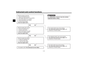
the vehicle upright.TIPThe built-in sidestand switch is part of
the ignition circuit cut-off system,
which cuts the ignition in certain situa-
tions. (See the following section for an
explanation of the ignition circuit cut-
off system.)
WARNING
EWA10242
The vehicle must not be ri dden with
the si destan d d own, or if the si de-
stan d cannot b e properly moved up
(or does not stay up), otherwise the
si destan d coul d contact the groun d
an d d istract the operator, resultin g
in a possi ble loss of control.
Yamaha’s i gnition circuit cut-off
system has been desi gne d to assist
the operator in fulfillin g the respon-
si bility of raisin g the si destan d b e-
fore startin g off. Therefore, check
1. Helmet holderZAUM2033
1
UBFGE0E0.book Page 17 Friday, April 9, 2021 9:25 AM