Page 49 of 114

Instrument and control functions
6-15
6
EAU13213
FuelMake sure there is sufficient gasoline in
the tank.
WARNING
EWA10882
Gasoline and gasoline vapors are
extremely flammable. To avoid fires
and explosions and to reduce the
risk of injury when refueling, follow
these instructions.1. Before refueling, turn off the en-
gine and be sure that no one is sit-
ting on the vehicle. Never refuel
while smoking, or while in the vi-
cinity of sparks, open flames, or
other sources of ignition such as
the pilot lights of water heaters
and clothes dryers.
2. Do not overfill the fuel tank. Stop
filling when the fuel reaches the
bottom of the filler tube. Because
fuel expands when it heats up,
heat from the engine or the sun
can cause fuel to spill out of the
fuel tank.3. Wipe up any spilled fuel immedi-
ately. NOTICE: Immediately
wipe off spilled fuel with a clean,
dry, soft cloth, since fuel may
deteriorate painted surfaces or
plastic parts.
[ECA10072]
4. Be sure to securely close the fuel
tank cap.
WARNING
EWA15152
Gasoline is poisonous and can
cause injury or death. Handle gaso-
line with care. Never siphon gasoline
by mouth. If you should swallow
some gasoline or inhale a lot of gas-
oline vapor, or get some gasoline in
your eyes, see your doctor immedi-ately. If gasoline spills on your skin,
wash with soap and water. If gaso-
line spills on your clothing, change
your clothes.
EAU86072
Your Yamaha engine was designed to
use unleaded gasoline with a research
octane number of 90 or higher. If en-
gine knocking or pinging occurs, use a
gasoline of a different brand or higher
octane rating.TIPThis mark identifies the recom-
mended fuel for this vehicle as
specified by European regulation
(EN228).
1. Fuel tank filler tube
2. Maximum fuel level
1
2
Recommended fuel:
Unleaded gasoline only
Octane number (RON):
90
Fuel tank capacity:
7.1 L (1.9 US gal, 1.6 Imp.gal)
Fuel tank reserve:
1.7 L (0.45 US gal, 0.37 Imp.gal)
UBALE0E0.book Page 15 Wednesday, September 30, 2020 1:37 PM
Page 50 of 114

Instrument and control functions
6-16
6Confirm the gasoline pump nozzle
has the same fuel identification
mark.
Gasohol
There are two types of gasohol: gaso-
hol containing ethanol and that con-
taining methanol. Gasohol containing
ethanol can be used if the ethanol con-
tent does not exceed 10% (E10). Gas-
ohol containing methanol is not
recommended by Yamaha because it
can cause damage to the fuel system
or vehicle performance problems.NOTICE
ECA11401
Use only unleaded gasoline. The use
of leaded gasoline will cause severe
damage to internal engine parts,
such as the valves and piston rings,
as well as to the exhaust system.
EAU86150
Fuel tank overflow hoseThe overflow hose drains excess gaso-
line and directs it safely away from the
vehicle.
Before operating the vehicle:
Check the fuel tank overflow hose
connection and routing.
Check the fuel tank overflow hose
for cracks or damage, and replace
it if necessary.
Make sure that the fuel tank over-
flow hose is not blocked, and
clean it if necessary.
EAU13435
Catalytic converterThe exhaust system contains catalytic
converter(s) to reduce harmful exhaust
emissions.
WARNING
EWA10863
The exhaust system is hot after op-
eration. To prevent a fire hazard or
burns:
Do not park the vehicle near
possible fire hazards such as
grass or other materials that
easily burn.
Park the vehicle in a place
where pedestrians or children
are not likely to touch the hot
exhaust system.
Make sure that the exhaust sys-
tem has cooled down before
doing any maintenance work.
Do not allow the engine to idle
more than a few minutes. Long
idling can cause a build-up of
heat.
1. Fuel tank overflow hose
1
UBALE0E0.book Page 16 Wednesday, September 30, 2020 1:37 PM
Page 51 of 114

With the mechanical ke")
Instrument and control functions
6-17
6
EAU89400
SeatTo open the seat
Via the main switchTurn the main switch to “OPEN”, and
then push the “SEAT” button. (See
page 3-9.)
With the mechanical key1. Open the keyhole cover.
2. Insert the mechanical key into the
seat lock, and then turn it clock-
wise.
3. Lift the rear of the seat.
NOTICE
ECA24020
Make sure that the keyhole cover is
installed when the mechanical key is
not being used.To close the seat
Push the rear of the seat down to lock
it in place.TIPMake sure that the seat is properly se-
cured before riding.
EAU37482
Helmet holdersThe helmet holders are located under
the seat.
To secure a helmet to a helmet hold-
er
1. Open the seat. (See page 6-17.)
2. Attach a helmet to a helmet hold-
er, and then securely close the
seat. WARNING! Never ride with
a helmet attached to the helmet
holder, since the helmet may hit
objects, causing loss of control
and possibly an accident.
[EWA10162]
1. Keyhole cover
2. Seat lock
3. Unlock.
13
2
1. Helmet holder
1
UBALE0E0.book Page 17 Wednesday, September 30, 2020 1:37 PM
Page 52 of 114
Instrument and control functions
6-18
6To release a helmet from a helmet
holder
Open the seat, remove the helmet from
the helmet holder, and then close the
seat.
EAUN2612
Storage compartmentsThis model is equipped with 3 storage
compartments. The front storage com-
partments and rear storage compart-
ment are located as shown.
TIPSome helmets cannot be stored in the
rear storage compartment because of
their size or shape.Storage compartment B
To open storage compartment B, pull
up the storage compartment lid to un-
lock it, and then open.
To close storage compartment B, push
the storage compartment lid into the
original position.
1. Storage compartment A
2. Storage compartment B
1. Rear storage compartment12
1
1. Lid
2. Storage compartment B
12
UBALE0E0.book Page 18 Wednesday, September 30, 2020 1:37 PM
Page 53 of 114

Instrument and control functions
6-19
6 Rear storage compartment
To open the rear storage compart-
ment, turn the main switch to “OPEN”,
and then push the “SEAT” button.
TIPDo not leave your vehicle unattended
with the seat open.NOTICE
ECA21150
Keep the following points in mind
when using the storage compart-
ment.
Since the storage compartment
accumulates heat when ex-
posed to the sun and/or the en-
gine heat, do not store anything
susceptible to heat, consum-
ables or flammable items inside
it.
To avoid humidity from spread-
ing through the storage com-
partment, wrap wet articles in a
plastic bag before storing them
in the compartment.Since the storage compartment
may get wet while the vehicle is
being washed, wrap any articles
stored in the compartment in a
plastic bag.
Do not keep anything valuable
or breakable in the storage
compartment.
WARNING
EWA18950
Do not exceed the load limit of
1.5 kg (3.3 lb) for storage com-
partment A.
Do not exceed the load limit of
0.3 kg (1 lb) for storage com-
partment B.
Do not exceed the load limit of
5.0 kg (11 lb) for the rear storage
compartment.
Do not exceed the maximum
load of 167 kg (368 lb) for the ve-
hicle.
EAUN3020
Adjusting the shock absorber
assembliesEach shock absorber assembly is
equipped with a spring preload adjust-
ing ring.
WARNING
EWA10211
Always adjust both shock absorber
assemblies equally, otherwise poor
handling and loss of stability may re-
sult.To adjust the spring preload
Turn the adjusting ring in direction (a)
to increase the spring preload.
Turn the adjusting ring in direction (b)
to decrease the spring preload.
Align the appropriate number (1 or 2) in
the adjusting ring with the position indi-
cator on the shock absorber.
UBALE0E0.book Page 19 Wednesday, September 30, 2020 1:37 PM
Page 54 of 114

Instrument and control functions
6-20
6
EAUN2161
Power outlet This model is equipped with a 12V DC
power outlet.NOTICE
ECAN0140
Do not use the power outlet when
the engine is off, and do not exceed
the specified electrical load; other-
wise the fuse may blow or the bat-
tery may discharge.
When washing the vehicle, do not di-
rect high-pressure washers at the
power outlet area.
To use the power outlet
1. Turn the vehicle power off.
2. Remove the power outlet cap.
3. Turn the accessory off.
4. Insert the accessory plug into the
power outlet.
5. Turn the vehicle power on and
start the engine.
6. Turn the accessory on.TIPWhen finished riding, turn off the ac-
cessory and disconnect it from the
power outlet, and then install the cap.
1. Position indicator
2. Spring preload adjusting ringSpring preload setting:
Position 1: Standard
Position 2: Hard
21
(a)(b)
1. Power outletMaximum electrical load:
12 W (1A)1
1. Power outlet cap1
UBALE0E0.book Page 20 Wednesday, September 30, 2020 1:37 PM
Page 55 of 114

Instrument and control functions
6-21
6
WARNING
EWAN0050
To prevent electrical shock or short-
circuiting, install the cap when the
power outlet is not in use.
EAU15306
SidestandThe sidestand is located on the left
side of the frame. Raise the sidestand
or lower it with your foot while holding
the vehicle upright.TIPThe built-in sidestand switch is part of
the ignition circuit cut-off system,
which cuts the ignition in certain situa-
tions. (See the following section for an
explanation of the ignition circuit cut-
off system.)
WARNING
EWA10242
The vehicle must not be ridden with
the sidestand down, or if the side-
stand cannot be properly moved up
(or does not stay up), otherwise the
sidestand could contact the ground
and distract the operator, resulting
in a possible loss of control.
Yamaha’s ignition circuit cut-off
system has been designed to assist
the operator in fulfilling the respon-
sibility of raising the sidestand be-
fore starting off. Therefore, checkthis system regularly and have a
Yamaha dealer repair it if it does not
function properly.
UBALE0E0.book Page 21 Wednesday, September 30, 2020 1:37 PM
Page 56 of 114
Instrument and control functions
6-22
6
EAUT1098
Ignition circuit cut-off systemCheck the operation of the sidestand
switch according to the following pro-
cedure.UBALE0E0.book Page 22 Wednesday, September 30, 2020 1:37 PM
 1
1 2
2 3
3 4
4 5
5 6
6 7
7 8
8 9
9 10
10 11
11 12
12 13
13 14
14 15
15 16
16 17
17 18
18 19
19 20
20 21
21 22
22 23
23 24
24 25
25 26
26 27
27 28
28 29
29 30
30 31
31 32
32 33
33 34
34 35
35 36
36 37
37 38
38 39
39 40
40 41
41 42
42 43
43 44
44 45
45 46
46 47
47 48
48 49
49 50
50 51
51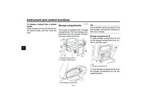 52
52 53
53 54
54 55
55 56
56 57
57 58
58 59
59 60
60 61
61 62
62 63
63 64
64 65
65 66
66 67
67 68
68 69
69 70
70 71
71 72
72 73
73 74
74 75
75 76
76 77
77 78
78 79
79 80
80 81
81 82
82 83
83 84
84 85
85 86
86 87
87 88
88 89
89 90
90 91
91 92
92 93
93 94
94 95
95 96
96 97
97 98
98 99
99 100
100 101
101 102
102 103
103 104
104 105
105 106
106 107
107 108
108 109
109 110
110 111
111 112
112 113
113
