Page 25 of 108

Instrument and control functions
4-6
4
EAU88280
Turn si gnal in dicator li ghts “ ”
an d“”
Each indicator light will flash when its
corresponding turn signal lights are
flashing.
EAU88300
Neutral in dicator li ght “ ”
This indicator light comes on when the
transmission is in the neutral position.
EAU88310
Hi gh beam in dicator li ght “ ”
This indicator light comes on when the
high beam of the headlight is switched
on.
EAU88320
Fuel level warning light “ ”
This warning light comes on when the
fuel level drops below approximately
2.8 L (0.74 US gal, 0.62 Imp.gal). When
this occurs, refuel as soon as possible.
The electrical circuit of the warning
light can be checked by turning the ve-
hicle on. The warning light should
come on for a few seconds, and then
go off.
TIPIf the warning light does not come on at
all, remains on after refueling, or if the
warning light flashes repeatedly, have
a Yamaha dealer check the vehicle.
EAU88331
Malfunction in dicator li ght
(MIL) “ ”
This light comes on or flashes if a prob-
lem is detected in the engine or other
vehicle control system. If this occurs,
have a Yamaha dealer check the on-
board diagnostic system. The electri-
cal circuit of the warning light can be
checked by turning the vehicle power
on. The light should come on for a few
seconds, and then go off. If the light
does not come on initially when the ve-
hicle power is turned on, or if the light
remains on, have a Yamaha dealer
check the vehicle.NOTICE
ECA26820
If the MIL starts flashin g, re duce en-
g ine spee d to prevent exhaust sys-
tem damag e.
TIPThe engine is sensitively monitored by
the on-board diagnostic system to de-
tect deterioration or malfunction of the
emission control system. Therefore the
MIL may come on or flash due to vehi-
cle modifications, lack of maintenance,
or excessive/improper use of the mo-
torcycle. To prevent this, observe
these precautions.
Do not attempt to modify the soft-
ware of the engine control unit.
Do not add any electrical acces-
sories that interfere with engine
control.
Do not use aftermarket accesso-
ries or parts such as suspension,
spark plugs, injectors, exhaust
system, etc.
Do not change the drivetrain
specifications (chain, sprockets,
wheels, tires, etc.).
Do not remove or alter the O2 sen-
sor, air induction system, or ex-
haust parts (catalysts or EXUP,
etc.).
Maintain the drive chain properly.
Maintain correct tire pressure.
UB7NE0E0.book Page 6 Friday, October 2, 2020 4:38 PM
Page 26 of 108

Instrument and control functions
4-7
4
Maintain proper brake pedal
height to prevent rear brake from
dragging.
Do not operate the vehicle in an
extreme manner. For example, re-
peated or excessive opening and
closing of the throttle, racing,
burnouts, wheelies, extended
half-clutch use, etc.
EAU91500
ABS warnin g li ght “ ”
In normal operation, the ABS warning
light comes on when the vehicle is
turned on, and goes off after traveling
at a speed of 5 km/h (3 mi/h) or higher.TIPIf the warning light does not work as
described above, or if the warning light
comes on while riding, the ABS may
not work correctly. Have a Yamaha
dealer check the vehicle as soon as
possible.
WARNING
EWA21120
If the ABS warnin g lig ht does not
turn off after reachin g 5 km/h (3
mi/h), or if the warnin g li ght comes
on while ri din g:
Use extra caution to avoi d pos-
si ble wheel lock durin g emer-
g ency brakin g.
Have a Yamaha dealer check
the vehicle as soon as possi ble.
EAU88350
Immo bilizer system in dicator
li g ht “ ”
When the main switch is turned off and
30 seconds have passed, the indicator
light will flash steadily to indicate the
immobilizer system is enabled. After 24
hours have passed, the indicator light
will stop flashing, however the immobi-
lizer system is still enabled.TIPWhen the vehicle is turned on, this light
should come on for a few seconds and
then go off. If the light does not come
on, or if the light remains on, have a
Yamaha dealer check the vehicle.
Transpon der interference
If the immobilizer system indicator light
flashes in the pattern, slowly 5 times
then quickly 2 times, this could be
caused by transponder interference. If
this occurs, try the following. 1. Make sure there are no other im- mobilizer keys close to the main
switch.
2. Use the code re-registering key to start the engine.
3. If the engine starts, turn it off, and try starting the engine with the
standard keys.
4. If one or both of the standard keys do not start the engine, take the
vehicle and all 3 keys to a Yamaha
dealer to have the standard keys
re-registered.
EAU91471
Sta bility control in dicator li ght “ ”
This indicator light flashes when the
TCS, SCS, or LIF systems engage
while riding. When “TCS-MODE” is set
to “OFF”, the indicator will come on.
UB7NE0E0.book Page 7 Friday, October 2, 2020 4:38 PM
Page 27 of 108

Instrument and control functions
4-8
4
TIPWhen the vehicle is turned on, this light
should come on for a few seconds and
then go off. If the light does not come
on, or if the light remains on, have a
Yamaha dealer check the vehicle.NOTICE
ECA27221
When turnin g the main switch on,
avoi d any movement or vi bration of
the vehicle as it may interfere with
the initialization of the IMU. If this
occurs, the TCS system will not op-
erate an d the “TCS-MODE” display
will rea d “OFF” until the IMU can ini-
tialize.
EAU88362
Oil pressure an d Coolant tempera-
ture warnin g li ght “ ”
This warning light comes on if the en-
gine oil pressure is low or if the coolant
temperature is high. If this occurs, stop
the engine immediately.TIP When the vehicle is first turned on,
this light should come on until the
engine is started.
If a malfunction is detected, this
light will come on and the oil pres-
sure icon will flash.
NOTICE
ECA22441
If the oil pressure an d coolant warn-
in g li ght does not g o off after start-
in g the en gine or if it comes on while
the en gine is runnin g, stop the vehi-
cle an d en gine imme diately.
If the en gine is overheatin g, the
coolant temperature warnin g
icon will come on. Let the en-
g ine cool. Check the coolant
level (see pa ge 7-35).
If the en gine oil pressure is low,
the oil pressure warnin g icon
will come on. Check the oil level
(see pa ge 7-10).
If the warnin g lig ht remains on
after lettin g the en gine cool an d
confirmin g the proper oil level,
have a Yamaha d ealer check
the vehicle. Do not continue to
operate the vehicle!
EAU88370
Auxiliary system warnin g lig ht “ ”
This warning light comes on if a prob-
lem is detected in a non-engine-related
system.TIPWhen the vehicle is turned on, this light
should come on for a few seconds and
then go off. Otherwise, have a Yamaha
dealer check the vehicle.
UB7NE0E0.book Page 8 Friday, October 2, 2020 4:38 PM
Page 28 of 108
 for
good contrast and")
Instrument and control functions
4-9
4
EAU91445
DisplayThe following items can be found on
the display:
TIPThis model uses a thin-film-transistor
liquid-crystal display (TFT LCD) for
good contrast and readability in vari-
ous lighting conditions. However, due
to the nature of this technology, it is
normal for a small number of pixels to
be inactive.
WARNING
EWA18210
Stop the vehicle b efore making any
settin g chan ges. Chan gin g settin gs
while ri din g can d istract the opera-
tor an d increase the risk of an acci-
d ent.Speed ometer
The speedometer shows the vehicle’s
traveling speed.TIPThe display can be switched between
page 4-17.
1. Tachometer
2. Speedometer
3.
4. Transmission gear display
5. Vehicle information displays
6. Settings MENU icon Ž
7. Grip warmer indicator (option)
8.
9. Clock
10.MODE display
11.Lap timer
12.Oil pressure warning Ž
13.Coolant temperature warning Ž
14.Auxiliary system warning Ž
when activated)
LAP 02LATEST
00:12.3 4
00:01.23
4
1
2
7
6
9
10
8
1135
14 13
12
15
UB7NE0E0.book Page 9 Friday, October 2, 2020 4:38 PM
Page 29 of 108
.
NOTICE
ECA10032")
Instrument and control functions
4-10
4
Tachometer
The tachometer shows the engine
speed, as measured by the rotational
velocity of the crankshaft, in revolu-
tions per minute (r/min).
NOTICE
ECA10032
Do not operate the en
gine in the ta-
chometer red zone.
Re d zone: 10600 r/min an d a boveVehicle information displays
The two vehicle information displays
can be individually set to show the fol-
lowing items: ODO: odometer
F-TRIP: fuel reserve tripmeter
TRIP1: tripmeter
TRIP2: tripmeter
F.AVE: average fuel economy
F.CRNT: instantaneous fuel econ-
omy
A.TEMP: air temperature
C.TEMP: coolant temperature
Fuel meter
FUELCON: amount of fuel con-
sumed
TRIPTIME: running time
Operate the vehicle information display
as follows:
Rotate the wheel switch to move the
cursor over a display.
Push the wheel switch inward and the
selected display will highlight grey.
Rotate the wheel switch to choose a
different display item.
Push the wheel switch inward to con-
firm the new display item.
TIP ODO will lock at 999999 and can-
not be reset.
TRIP1 and TRIP2 will reset to 0
and begin counting again after
9999.9 has been reached.
When the fuel tank reserve level
has been reached, F-TRIP ap-
pears automatically and begins
recording distance traveled from
that point.
After refueling and traveling some
distance, F-TRIP will automatically
disappear.
See “Unit” on page 4-17 to chan-
ge the fuel consumption units.
The air temperature is displayed
from –9 °C (16 °F) to 50 °C (122 °F)
in 1 °C (1 °F) increments.
The air temperature displayed
may vary from the actual ambient
temperature.
In LAP TIME mode, the vehicle in-
formation display is replaced by
the lap information.
TRIP1, TRIP2, F-TRIP, F.AVE, FU-
ELCON and TRIPTIME items can
be individually reset.
If the vehicle coolant temperature
is below 40 °C (104 °F) the coolant
temperature display will read “Lo”
1. Vehicle information displays
1
UB7NE0E0.book Page 10 Friday, October 2, 2020 4:38 PM
Page 30 of 108
 the cool-
ant temperature display will read
“Hi”
To reset information display items1. Rota")
Instrument and control functions
4-11
4
If the vehicle coolant temperature
is above 124 °C (255 °F) the cool-
ant temperature display will read
“Hi”
To reset information display items1. Rotate the wheel switch to select
one of the two vehicle information
displays.
2. Press the wheel switch inward to highlight the information display.
3. Rotate the wheel switch to select the desired information display
item.
4. Press and hold the wheel switch inward until the highlighted dis-
play item is reset.
Transmission gear display
This shows which gear the transmis-
sion is in. This model has 6 gears and a
neutral position. The neutral position is
indicated by the neutral indicator
light “ ” and by the transmission gear
display “ ”. MODE
display
This display shows the currently se-
lected “D-MODE” and “TCS-MODE”
settings. The mode that is enlarged
and displayed on the right can be ad-
justed using the MODE up/down
switches. Use the “MODE” switch to
toggle left-right between “TCS-MODE”
and “D-MODE”.
See page 3-1 for information on “D-
MODE” and “TCS-MODE” settings.
TIP When the malfunction indicator
light “ ”, the auxiliary system
warning “ ”, or the coolant
temperature warning “ ” are on,
“D-MODE” and “TCS-MODE”
cannot be adjusted.
The previously selected modes
will be displayed when the vehicle
power is turned on.
To turn off the traction control system,
select “TCS-MODE” with the “MODE”
switch, then push and hold the MODE
up switch until “OFF” is displayed. To
turn TCS back on, press the MODE
down switch (“TCS-MODE” will return
to its previous setting).TIPWhen “TCS-MODE” has been set
to “OFF”, the TCS, SCS and LIF
systems are all turned off togeth-
er.
The “TCS-MODE OFF” and “TCS-
M OD E M ” se t ti ng s c a n o n l y b e s e -
lected while the vehicle is
stopped.Clock
The clock uses a 12-hour time system.
See page 4-17 to set the clock.
Quick shift in dicator “QS”
When able to shift, the respective QS or turns green.
UB7NE0E0.book Page 11 Friday, October 2, 2020 4:38 PM
Page 31 of 108

Instrument and control functions
4-12
4
When unable to shift, QS is
white.
If the QS function is turned OFF, QS
itself is not displayed.
The QS functions can be turned on or
off in the setting MENU. See page
4-15.
TIPThe upshift and downshift functions
are independent and can be activated
separately.
For more information on the QS sys-
Settin g menu icon “ ”
Choose this icon and push the wheel
switch to change the settings MENU
screen. (See page 4-14.)
Grip warmer in dicator (Option)
The grip warmers can be used when
the engine is running. There are 10
temperature levels. When activated,
the indicator will display the tempera-
ture level from 1 (lowest) to 10 (high-
est). To activate the grip warmer, use the
wheel switch to highlight the grip
warmer display with the cursor.
Press the wheel switch inward to se-
lect the grip warmer function.
Once selected, rotate the wheel switch
up and down to adjust the temperature
level.
Press the wheel switch inward to con-
firm the temperature level and exit the
grip warmer function.
NOTICE
ECA17932
Be sure to wear g loves when
using the grip warmers.
Do not use the grip warmers in
warm weather.
If the han dle bar grip or throttle
g rip becomes worn or d am-
a g ed , stop usin g the g rip warm-
ers an d replace the grips.The function of the wheel switch can
be locked into grip warmer mode by
pressing and holding the wheel switch
inward while the grip warmer indicator
is highlighted by the cursor. In this mode, the temperature levels
can be instantly adjusted by rotating
the wheel switch up/down.
To exit this mode and return the wheel
switch to its normal functionality, press
and hold the wheel switch inward.
TIPThe current grip warmer setting is
saved when the vehicle is turned off.Lap timer
This stopwatch function can be acti-
vated through the setting MENU. (See
page 4-14.)
Once activated, the vehicle information
display is replaced with:1. Lap count
2. Current lap time
3. Latest/Previous lap time
LAP
02
LATEST
00:12.3
4
00:3 0.23
2
1
3
UB7NE0E0.book Page 12 Friday, October 2, 2020 4:38 PM
Page 32 of 108

Instrument and control functions
4-13
4 To start the timer, press the pass
switch.
Each press of the pass switch will in-
crease the lap count by 1 and reset the
current lap timer.
To pause the lap timer, press the wheel
switch inward.
To unpause the timer, press the pass
switch and the timer will resume with-
out counting a new lap.
To exit the lap time mode, turn it off in
the settings MENU. (See page 4-14.)
TIP
The engine must be running to
start the lap timer.
The headlight will flash when the
pass switch is pressed.
Whenever the lap timer is paused,
it can be resumed using the pass
switch.Brake control icon “BC”
This icon is replaced by the auxiliary
system warning and coolant tempera-
ture warning indicators when they are
activated.
For more information on the BC sys-
tem see “BC” on page 3-4. Error mo
de warnin g “Err”
When an internal error occurs (e.g.,
communication with a system control-
ler has been cut off), the error mode
warning will appear as follows.
“Err” and “ ” indicator light indicates
an ECU error.
“Err” only indicates an ABS ECU error.
TIPDepending on the nature of the error,
the display may not function properly
and TCS settings may be impossible to
change. Additionally, ABS may not
function properly. Use extra care when
braking and have a Yamaha dealer
check the vehicle immediately.Auxiliary system warnin g“”
This icon appears if a problem is de-
tected in a non-engine-related system.
Coolant temperature warnin g“”
This icon appears if the coolant tem-
perature reaches 116 °C (241 °F) or
higher. Stop the vehicle and turn off the
engine. Allow the engine to cool.
NOTICE
ECA10022
Do not continue to operate the en-
g ine if it is overheatin g.Oil pressure warnin g“”
This icon appears when the engine oil
pressure is low. When the vehicle is
first turned on, engine oil pressure has
yet to build, so this icon will come on
and stay on until the engine has been
started.TIPIf a malfunction is detected, the oil
pressure warning icon will flash repeat-
edly.NOTICE
ECA26410
Do not continue to operate the en-
g ine if the oil pressure is low.
UB7NE0E0.book Page 13 Friday, October 2, 2020 4:38 PM
 1
1 2
2 3
3 4
4 5
5 6
6 7
7 8
8 9
9 10
10 11
11 12
12 13
13 14
14 15
15 16
16 17
17 18
18 19
19 20
20 21
21 22
22 23
23 24
24 25
25 26
26 27
27 28
28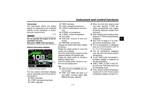 29
29 30
30 31
31 32
32 33
33 34
34 35
35 36
36 37
37 38
38 39
39 40
40 41
41 42
42 43
43 44
44 45
45 46
46 47
47 48
48 49
49 50
50 51
51 52
52 53
53 54
54 55
55 56
56 57
57 58
58 59
59 60
60 61
61 62
62 63
63 64
64 65
65 66
66 67
67 68
68 69
69 70
70 71
71 72
72 73
73 74
74 75
75 76
76 77
77 78
78 79
79 80
80 81
81 82
82 83
83 84
84 85
85 86
86 87
87 88
88 89
89 90
90 91
91 92
92 93
93 94
94 95
95 96
96 97
97 98
98 99
99 100
100 101
101 102
102 103
103 104
104 105
105 106
106 107
107