Page 17 of 108

Special features
3-2
3
This traction control system automati-
cally adjusts according to the vehicle’s
lean angle. To maximize acceleration,
when the vehicle is upright a lesser
amount of traction control is applied.
When cornering, a greater amount of
traction control is applied.
TIP
The traction control system may
engage when the vehicle travels
over a bump.
You may notice slight changes in
engine and exhaust sounds when
the traction control or other sys-
tems engage.
The traction control system can
only be turned off by setting “TCS-
MODE” to “OFF”, using the MODE switches. See page 4-4 for more
information on “TCS-MODE”.
When “TCS-MODE” has been set
to “OFF”, the TCS, SCS and LIF
systems are all turned off togeth-
er.
WARNING
EWA15433
The traction control system is not a
substitute for ri din g appropriately
for the con ditions. Traction control
cannot prevent loss of traction d ue
to excessive spee d when enterin g
turns, when acceleratin g har d at a
sharp lean an gle, or while brakin g,
an d cannot prevent front wheel slip-
pin g. As with any vehicle, approach
surfaces that may be slippery with
caution an d avoi d especially slip-
pery surfaces.When the vehicle power is on, the trac-
tion control system automatically turns
on. The traction control system can be
turned on or off manually only when
the key is in the “ON” position and the
motorcycle is stopped.
TIP
the rear wheel if the motorcycle gets
stuck in mud, sand, or other soft sur-
faces.NOTICE
ECA16801
Use only the specifie d tires. (See
pa ge 7-15.) Usin g different size d
tires will prevent the traction control
system from controllin g tire rotation
accurately.SCS
The slide control system regulates en-
gine power output when a sideward
slide is detected in the rear wheel. It
adjusts power output based on data
from the IMU (Inertial Measurement
Unit). This system supports the TCS to
contribute to a smoother ride.
LIF
The lift control system reduces the rate
at which the front wheel rises during
extreme acceleration, such as during
starts or out-of-corner exits. When
front-wheel lift is detected, engine
TCS
UB7NE0E0.book Page 2 Friday, October 2, 2020 4:38 PM
Page 18 of 108

Special features
3-3
3power is regulated to slow front-wheel
lift while still providing good accelera-
tion.
EAU91340
QSSThe quick shift system allows for clutch
lever-less, electronically-assisted shift-
ing. When the sensor on the shift rod
detects the appropriate motion in the
shift pedal, engine power output is mo-
mentarily adjusted to allow for the gear
change to occur.
QSS does not operate when the clutch
lever is pulled, therefore normal shifting
can be done even when QSS is set to
on. Check the QS indicator for current
status and usability information.
Upshiftin
g con ditions
Vehicle speed of at least 20 km/h
(12 mi/h)
Engine speed of at least 2200
r/min
Accelerating (open throttle)
Downshiftin g con ditions
Vehicle speed of at least 20 km/h
(12 mi/h)
Engine speed of at least 2000
r/min
Engine speed sufficiently away
from red zone
Decelerating and throttle fully-
closed
TIPQS and QS can be individ-
ually set.
Shifting into or out of neutral must
be done using the clutch lever.
QSS usa bility In dicator
Upshifting OK
Downshifting OK
QSS cannot be used QSS turned off
UB7NE0E0.book Page 3 Friday, October 2, 2020 4:38 PM
Page 19 of 108
Special features
3-4
3
EAU91350
BCThe brake control system regulates hy-
draulic brake pressure for the front and
rear wheels when the brakes are ap-
plied and wheel lock is detected. This
system has two settings.
BC1 is standard ABS, which adjusts
brake pressure based on vehicle
speed and wheel speed data. BC1 is
designed to engage and maximize
braking when the vehicle is upright.
BC2 uses additional data from the IMU
to regulate applied brake power when
cornering to suppress lateral wheel
slip.
WARNING
EWA20891
The brake control system is not a
su bstitute for the use of proper ri d-
in g an d brakin g techniques. The
b rake control system cannot pre-
vent all loss of traction due to over-
b rakin g from excessive spee d, or
lateral wheel slip when brakin g on
slippery surfaces.
ABS
BC1/BC2 BC2 BC2
UB7NE0E0.book Page 4 Friday, October 2, 2020 4:38 PM
Page 20 of 108

Instrument and control functions
4-1
4
EAU1097B
Immo bilizer systemThis vehicle is equipped with an immo-
bilizer system to help prevent theft by
re-registering codes in the standard
keys. This system consists of the fol-
lowing:
a code re-registering key
two standard keys
a transponder (in each key)
an immobilizer unit (on the vehicle)
an ECU (on the vehicle)
a system indicator light (page 4-7) A
bout the keys
The code re-registering key is used to
register codes in each standard key.
Store the code re-registering key in a
safe place. Use a standard key for daily
operation.
When key replacement or re-register-
ing is necessary, bring the vehicle and
the code re-registering key along with
any remaining standard keys to a
Yamaha dealer to have them re-regis- tered.
TIP Keep the standard keys as well as
keys of other immobilizer systems
away from the code re-registering
key.
Keep other immobilizer system
keys away from the main switch
as they may cause signal interfer-
ence.NOTICE
ECA11823
DO NOT LOSE THE CODE RE-REG-
ISTERING KEY! CONTACT YOUR
DEALER IMMEDIATELY IF IT IS
LOST! If the cod e re-registering key
is lost, the existin g stan dar d keys can still b
e used to start the vehicle.
However, re gisterin g a new stan-
d ar d key is impossi ble. If all keys
have been lost or damag ed , the en-
tire immo bilizer system must be re-
placed . Therefore, han dle the keys
carefully. Do not su bmerse in water.
Do not expose to hi gh tempera-
tures.
Do not place near mag nets.
Do not place near items that
transmit electrical si gnals.
Do not han dle rou ghly.
Do not grin d or alter.
Do not disassem ble.
Do not put two keys of any im-
mo bilizer system on the same
key rin g.
1. Code re-registering key (red bow)
2. Standard keys (black bow)UB7NE0E0.book Page 1 Friday, October 2, 2020 4:38 PM
Page 21 of 108

Instrument and control functions
4-2
4
EAU10474
Main switch/steerin g lockThe main switch/steering lock controls
the ignition and lighting systems, and is
used to lock the steering. The various
positions are described below.TIPBe sure to use the standard key (black
bow) for regular use of the vehicle. To
minimize the risk of losing the code re-
registering key (red bow), keep it in a
safe place and only use it for code re-
registering.
EAU84031
ON
All electrical circuits are supplied with
power and the vehicle lights are turned
on. The engine can be started. The key
cannot be removed.TIP The headlight(s) will turn on when
the engine is started.
To prevent battery drain, do not
leave the key in the on position
without the engine running.
EAU10662
OFF
All electrical systems are off. The key
can be removed.
WARNING
EWA10062
Never turn the key to “OFF” or
“LOCK” while the vehicle is movin g.
Otherwise the electrical systems will
b e switched off, which may result in
loss of control or an acci dent.
EAU73800
LOCK
The steering is locked and all electrical
systems are off. The key can be re-
moved.
To lock the steering1. Turn the handlebars all the way to
the left.
2. With the key in the “OFF” position, push the key in and turn it to
“LOCK”.
3. Remove the key.
ON
OFF
LOCK
1. Push.
2. Turn.12
UB7NE0E0.book Page 2 Friday, October 2, 2020 4:38 PM
Page 22 of 108
Instrument and control functions
4-3
4
TIPIf the steering will not lock, try turning
the handlebars back to the right slight-
ly.To unlock the steeringPush the key in and turn it to “OFF”.
EAU66055
Han dle bar switchesLeft
Right
1. Push.
2. Turn.12
1. Pass switch Ž
2. Dimmer switch / Ž
3. Turn signal switch / Ž
4. Ž
5. Horn switch Ž
1 1 2
12
3
4
5
1. MODE up switch
2.
3. MODE down switch
1. Stop/Run/Start switch / / Ž
2. Wheel switch Ž
1 1
2
3 1
2
3
1 1 12 2
UB7NE0E0.book Page 3 Friday, October 2, 2020 4:38 PM
Page 23 of 108

Instrument and control functions
4-4
4
EAU91532
Pass switch “ ”
Press this switch to flash the headlight
and to mark the start of each lap when
using the lap timer.
EAU12402
Dimmer switch “ / ”
Set this switch to “ ” for the high
beam and to “ ” for the low beam.
EAU66040
Turn si gnal switch “ / ”
To signal a right-hand turn, push this
switch to “ ”. To signal a left-hand
turn, push this switch to “ ”. When
released, the switch returns to the cen-
ter position. To cancel the turn signal
lights, push the switch in after it has re-
turned to the center position.
EAU66030
Horn switch “ ”
Press this switch to sound the horn.
EAU66061
Stop/Run/Start switch “ / / ”
To crank the engine with the starter,
set this switch to “ ”, and then push
the switch down towards “ ”. See
page 6-2 for starting instructions prior to starting the engine.
Set this switch to “ ” to stop the en-
gine in case of an emergency, such as
when the vehicle overturns or when the
throttle cable is stuck.
EAU88272
Hazar
d switch “OFF/ ”
Use this switch to turn on the hazard
lights (simultaneous flashing of all turn
signal lights). The hazard lights are
used in case of an emergency or to
warn other drivers when your vehicle is
stopped where it might be a traffic haz-
ard.
The hazard lights can be turned on or
off only when the key is in the “ON” po-
sition. You can turn the main switch to
the “OFF” or “LOCK” position, and the
hazard lights will continue to flash. To
turn off the hazard lights, turn the main
switch to the “ON” position and oper-
ate the hazard switch again.NOTICE
ECA10062
Do not use the hazar d lig hts for an
exten ded len gth of time with the en-
g ine not runnin g, otherwise the bat-
tery may d ischarge.
EAU91362
MODE switches
Use the MODE switches to change the
“D-MODE” and “TCS-MODE” located
on the left side of the display.
There are three mode controls:
MODE up switch - push this switch to
change the selected mode setting up-
ward.
“MODE” switch - push this switch to
toggle left to right between “D-MODE”
and “TCS-MODE”.
MODE down switch - push this switch
to change the selected mode setting
downward.TIP When in “D-MODE 1”, pressing
the MODE up switch will cycle to
“D-MODE 4”. When in “D-MODE
4”, pressing the MODE down
switch will not cycle to “D-MODE
1”.
The “TCS-MODE” can only be
turned off from the main screen.
Select “TCS-MODE” with the
“MODE” switch, then push and
hold the MODE up switch until
“OFF” is displayed.
UB7NE0E0.book Page 4 Friday, October 2, 2020 4:38 PM
Page 24 of 108

Instrument and control functions
4-5
4
To turn the traction control system
back on, use the MODE down
switch.
When “TCS-MODE” has been set
to “OFF”, the TCS, SCS and LIF
systems are all turned off togeth-
er.
See page 4-11 for more informa-
tion on the MODE display.
See page 3-1 for more information
on “TCS-MODE”.
See page 3-1 for more information
on “D-MODE”.
EAU91373
Wheel switch “ ”
When the wheel switch is operated, a
cursor will appear around the previous-
ly selected item on the display.
The wheel switch controls:
Vehicle information displays
Settings MENU
Grip warmer function (Option)
Operate the wheel switch as follows:
Rotate up - rotate the wheel upward to
scroll up or increase a setting value.
Rotate down - rotate the wheel down-
ward to scroll down or decrease a set-
ting value. Push inwar
d - press the wheel switch
in towards the handlebar to select
items indicated by the cursor and con-
firm settings changes. Press and hold
the switch inward to reset selected
items.
TIP If the wheel switch is not operated
for a certain period of time, the
cursor will disappear.
For items that can be reset, leave
the cursor over the item, press
and hold the switch to reset.
See page 4-9 for more information
on the main screen and its func-
tions.
See page 4-14 for more informa-
tion on the MENU screen and how
to make settings changes.
EAU4939P
Indicator li ghts and warning
li g hts1. Immobilizer system indicator light “ ”
2. Left turn signal indicator light “ ”
3. Right turn signal indicator light “ ”
4. High beam indicator light “ ”
5. Neutral indicator light “ ”
6. Stability control indicator light “ ”
7. Auxiliary system warning light “ ”
8. ABS warning light “ ”
9. Fuel level warning light “ ”
10.Oil pressure and Coolant temperature warn-
ing light “ ”
11.Malfunction indicator light “ ”
ABS
3
4
56
7
8
11 11
10 10
9
11 1 12
2 2
10 9 9
UB7NE0E0.book Page 5 Friday, October 2, 2020 4:38 PM
 1
1 2
2 3
3 4
4 5
5 6
6 7
7 8
8 9
9 10
10 11
11 12
12 13
13 14
14 15
15 16
16 17
17 18
18 19
19 20
20 21
21 22
22 23
23 24
24 25
25 26
26 27
27 28
28 29
29 30
30 31
31 32
32 33
33 34
34 35
35 36
36 37
37 38
38 39
39 40
40 41
41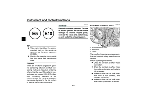 42
42 43
43 44
44 45
45 46
46 47
47 48
48 49
49 50
50 51
51 52
52 53
53 54
54 55
55 56
56 57
57 58
58 59
59 60
60 61
61 62
62 63
63 64
64 65
65 66
66 67
67 68
68 69
69 70
70 71
71 72
72 73
73 74
74 75
75 76
76 77
77 78
78 79
79 80
80 81
81 82
82 83
83 84
84 85
85 86
86 87
87 88
88 89
89 90
90 91
91 92
92 93
93 94
94 95
95 96
96 97
97 98
98 99
99 100
100 101
101 102
102 103
103 104
104 105
105 106
106 107
107
