2021 VOLVO V90 CROSS COUNTRY flat tire
[x] Cancel search: flat tirePage 13 of 683
11
Using Android Auto*
497
Settings for Android Auto *
498
Tips for using Android Auto *
498
Phone 499
Connecting a phone to the car via Bluetooth for the first time 500
Connecting a phone to the car viaBluetooth automatically 502
Connecting a phone to the car viaBluetooth manually 502
Disconnecting a Bluetooth-con-nected phone 502
Switch between phones con-nected via Bluetooth 503
Disconnecting Bluetooth-con-nected devices 503
Handling phone calls 503
Handling text messages 504
Text message settings 505
Managing the phone book 506
Phone settings 506
Settings for Bluetooth devices 507
Wireless phone charger *
508
Using the wireless phone charger *
508
Certificate for wireless charger 510
Internet-connected vehicle *
514
Connecting the vehicle to the Internet via a Bluetooth-connectedphone 515
Connecting the vehicle to theInternet via a phone (Wi-Fi) 515
Connecting the vehicle to theInternet via vehicle modem (SIM card) 516
Vehicle modem settings 517
Sharing Internet from the vehiclevia Wi-Fi hotspot (tethering) 518
No or poor Internet connection 519
Deleting Wi-Fi networks 519
Wi-Fi technology and security 520
Terms of use and data sharing 520
Activating and deactivating datasharing 521
Data sharing for services 521
Hard disk storage space 522
License agreement for audio andmedia 523
WHEELS AND TIRES
Tires
534
Tire direction of rotation 536
Tread wear indicator 537
Tire terminology 537
Tire sidewall designations 538
Uniform Tire Quality Grading 540
Checking tire pressure 541
Adjusting tire pressure 542
Recommended tire pressure 543
Tire pressure monitoring system *
543
Saving new reference values for tire inflation pressure monitoring *545
Viewing tire pressure status in thecenter display * 546
Action when warned of low tire pressure 547
Tire inflation pressure monitoring system * messages 548
Changing a wheel 548
Tool kit 550
Jack *
551
Wheel bolts 551
Spare wheel 552
Handling the spare wheel 553
Snow tires 554
Snow chains 555
Page 14 of 683

12
Tire sealing system556
Using the tire sealing system 557
Inflate tires with the compressor included in the tire sealing system 560
Determining the vehicle's permit-ted weight 561
LOADING, STORAGE AND PASSENGER COMPARTMENT
Passenger compartment interior
564
Tunnel console 565
Electrical outlets 566
Using the electrical outlets 567
Using the glove compartment 568
Sun visors 569
Cargo compartment 569
Loading recommendations 570
Roof loads and load carriers 571
Grocery bag holders 571
Load anchoring eyelets 572
Rear seat ski hatch 573
Installing and removing the cargo compartment cover * 573
Operating the cargo compartmentcover * 574
Installing and removing the steelcargo grid * 576
Installing and removing the cargo net *
577
MAINTENANCE AND SERVICE
Volvo's service program
582
Data transfer between vehicle and workshop over Wi-Fi 584
Download Center 585
Handling system updates viaDownload Center 585
Vehicle status 586
Scheduling service and repairs 587
Sending vehicle information to theworkshop 588
Hoisting the vehicle 589
Climate control system service 592
Replacing a windshield with head- up display * 592
Opening and closing the hood 592
Engine compartment overview 594
Engine oil 595
Checking and filling engine oil 596
Coolant 597
Refilling coolant 598
Starter battery 600
Support battery 602
Battery symbols 604
Battery recycling 604
Fuses and fuseboxes 605
Replacing fuses 605
Page 30 of 683

YOUR VOLVO
* Option/accessory.
28
Drive-E ‒ purer driving pleasure
Volvo is committed to the well-being of its customers. As a natural part of this commit-ment, we care about the environment inwhich we all live. Concern for the environ-ment means an everyday involvement inreducing our environmental impact.
Volvo's environmental activities are based on a holistic view, which means we consider theoverall environmental impact of a productthroughout its complete life cycle. In this con-text, design, production, product use, andrecycling are all important considerations. Inproduction, Volvo has partly or completelyphased out several chemicals including CFCs,lead chromates, asbestos, and cadmium; andreduced the number of chemicals used in ourplants 50% since 1991. Volvo was the first in the world to introduce into production a three-way catalytic converterwith a Lambda sond, now called the heatedoxygen sensor, in 1976. The current version ofthis highly efficient system reduces emissionsof harmful substances (CO, HC, NOx) from theexhaust pipe by approximately 95 - 99% andthe search to eliminate the remaining emis-sions continues. Volvo is the only automobilemanufacturer to offer CFC-free retrofit kits forthe air conditioning system of all models as farback as the 1975 model 240. Advanced elec-tronic engine controls and cleaner fuels arebringing us closer to our goal. In addition to continuous environmental refinement of con-ventional gasoline-powered internal combus-tion engines, Volvo is actively looking atadvanced technology alternative-fuel vehicles. When you drive a Volvo, you become our part- ner in the work to lessen the vehicle's impacton the environment. To reduce your vehicle'senvironmental impact, you can:
Maintain proper air pressure in your tires.Tests have shown decreased fuel econ-omy with improperly inflated tires.
Follow the recommended maintenanceschedule in your Warranty and ServiceRecords Information booklet.
Drive at a constant speed whenever possi-ble.
See a trained and qualified Volvo servicetechnician as soon as possible for inspec-tion if the check engine (malfunction indi-cator) light illuminates, or stays on afterthe vehicle has started.
Properly dispose of any vehicle-relatedwaste such as used motor oil, used batter-ies, brake pads, etc.
When cleaning your vehicle, please usegenuine Volvo car care products. All Volvocar care products are formulated to beenvironmentally friendly.
Related information
Economical driving (p. 435)
Starting and stopping preconditioning
*
(p. 234)
The Owner's Manual and the environment(p. 23)
Air quality (p. 209)
Page 58 of 683

SAFETY
56
Driver/passenger side front airbags
As a supplement to the seat belts, the vehicle is equipped with driver and passenger sidefront airbags.
Driver/passenger side front airbags.
In a frontal collision, the airbags help protect the driver's and passenger's head, neck, faceand chest and the driver's knees and legs. A collision of a sufficiently violent force will trigger the sensors and one or more airbagswill inflate. The airbag helps cushion the initial impact of the collision for the passenger. The airbag deflates when compressed by the colli-sion. A small amount of powder will also bereleased from the airbag. This may appear to be smoke and is normal. The entire process, from inflation to deflation of the airbag, occurswithin tenths of a second.
NOTE
The sensors react differently depending on the circumstances of the accident andwhether or not the seat belt is used. Thisapplies to all belt positions. There may therefore be accident situations in which only one (or none) of the airbagsare deployed. The sensors monitor theimpact of the collision and react accord-ingly to deploy one, several or no airbags.
WARNING
The seat belt and the airbag work together. If the seat belt is not used or is used incor-rectly, the airbag may not provide theintended protection in a collision. To help prevent injury in the event the air- bag is deployed, passengers should sit asupright as possible, with their feet on thefloor and their backs against the seat back-rest.
WARNING
Volvo recommends contacting an author- ized Volvo workshop for repairs. Incorrectlyperformed repairs to the airbag systemcould impair function and lead to seriousinjury.
The front airbag systemThe front airbag system includes gas genera- tors surrounded by the airbags, and decelera-tion sensors that activate the gas generators,causing the airbags to be inflated with nitro-gen gas. As the movement of the seats' occupants compresses the airbags, some of the gas isexpelled at a controlled rate to provide bettercushioning. The belt tensioners minimize slackin the seat belts and are activated for occu-pants wearing their seat belts. The entire proc-ess, from inflation to deflation of the airbag,occurs within tenths of a second. The location of the front airbags is indicated by SRS AIRBAG embossed on the steering
wheel pad and above the glove compartment,and by decals on both sun visors and on thefront and far right side of the dash. The driver's side front airbag is folded and
located in the steering wheel hub.The knee airbag is folded on the underside of
the dashboard on the driver's side. The text AIRBAG is embossed on the panel.
The passenger's side front airbag is folded
behind a panel located above the glove com-partment.
Page 387 of 683

DRIVER SUPPORT
* Option/accessory.385
The parking sequence is cancelledA parking sequence will be cancelled if: the driver moves the steering wheel
the vehicle's speed exceeds 7 km/h (4 mph)
the driver taps
Cancel in the center dis-
play
when the anti-lock brakes or the Elec- tronic stability control are engaged - e.g.when a wheel loses grip on a slippery road
when speed-dependent power steeringwheel resistance is working at reducedpower – e.g. during cooling due to over-heating
A message in the center display will explainwhy the parking sequence was cancelled.
CAUTION
Under certain circumstances, the function may not be able to find parking spaces –one reason may be that the sensors aredisrupted by external sound sources thatemit the same ultrasonic frequencies thatthe system works with. Examples of such sources include horns, wet tires on asphalt, pneumatic brakes,exhaust noise from motorcycles, etc.
NOTE
Dirt, ice and snow covering the sensors reduce their function and can make meas-urement impossible.
Driver responsibilityThe driver should keep in mind that the func- tion is a parking aid ‒ not an infallible fully
automatic system. The driver must always beprepared to take control and cancel a parkingsequence if necessary. There are a number of things to keep in mind when parking, including:
The driver is always responsible for deter-mining if the space suggested by the func- tion is suitable for parking.
Do not use the function when using snow chains or a temporary spare tire.
Do not use the function if there are anyobjects protruding from the vehicle.
Heavy rain or snowfall may inhibit PAP'sability to accurately measure a parkingspace.
While searching and measuring the park-ing space, the function may be unable todetect objects located far into the space.
PAP may not suggest parking spaces onnarrow streets if it does not detect suffi-cient space for maneuvering the vehicle.
Use approved tires 122
inflated to the cor-
rect tire pressure because this affects thefunction's ability to provide parking assis-tance.
The function is based on the way the vehi-cles are parked behind and in front of yourparking space. If they are, for example,parked too close to the curb, there is a riskthat your vehicle's tires or wheel rimscould be damaged by the curb during theparking procedure.
Perpendicular parking spaces may not bedetected or may be suggested unneces-sarily if a parked vehicle is sticking outmore than other parked vehicles.
The function is intended to provide park-ing assistance on straight streets, not sec-tions of street with sharp curves or bends.Always make sure that your vehicle is par-allel to relevant parking spaces when thefunction is measuring the parking space.
Related information
Park Assist Pilot
* (p. 379)
Speed-dependent steering wheel resis-tance (p. 278)
Camera/radar sensor limitations (p. 390)
122
"Approved tires" refers to tires of the same type and make as the vehicle's original, factory-installed tires.
Page 437 of 683
STARTING AND DRIVING
}}
* Option/accessory.435
Related information
Hill Descent Control (p. 433)
Changing drive mode
* (p. 421)
Economical driving
A more economical driving style can help lower fuel consumption.
Before driving
If possible, precondition the vehicle before driving.
If preconditioning is not possible when itis cold outside, use seat and steeringwheel heating first. Avoid heating theentire passenger compartment to reducethe amount of current being taken fromthe start battery.
Avoid using idling to warm up the vehiclebefore driving.
The type of tires and inflation pressureused could affect energy consumption –consult an authorized Volvo retailer foradvice on suitable tires.
Remove unnecessary items from the vehi-cle - the heavier the load, the higher thefuel consumption.
While driving
Activate Eco drive mode.
Use gear selector position
D as often as
possible.
When using manual gear shifting, drive using the highest possible gear. Use the gear indicator 19
.
Maintain a steady speed and a generous following distance to traffic ahead to mini-mize braking. Use engine braking if possi-ble.
Higher speeds increase energy consump-tion because air resistance increases withspeed.
In a cold climate, reduce heating of thewindshield/rear window, mirrors, seatsand the steering wheel.
Avoid driving with the windows open.
Do not use the accelerator pedal to keepthe vehicle stationary on an uphill gradi-ent. Instead, activate the auto-hold brakefunction at a standstill.
Use trip data to see current fuel consump-tion.
WARNING
Never turn off the engine while the vehicle is moving, e.g. when driving downhill. Thisdeactivates certain important systemssuch as power steering and brakes.
19
Only available in certain markets.
Page 539 of 683
WHEELS AND TIRES
}}
537
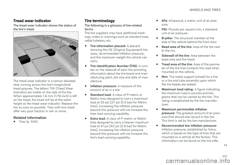
Tread wear indicatorThe tread wear indicator shows the status of the tire's tread.
The tread wear indicator is a narrow elevated strip running across the tire's longitudinaltread grooves. The letters TWI (Tread WearIndicator) are visible on the side of the tire.When approximately 1.6 mm (1/16 inch) is lefton the tread, the tread will be at the sameheight as the tread wear indicator. Replace thetire as soon as possible. Tires with low treadoffer very poor traction in rain or snow.
Related information
Tires (p. 534)
Tire terminology
The following is a glossary of tire-related terms.
The tire suppliers may have additional mark- ings, notes or warnings such as standard load,radial tubeless, etc.
Tire information placard
: A placard
showing the OE (Original Equipment) tiresizes, recommended inflation pressure,and the maximum weight the vehicle cancarry.
Tire Identification Number (TIN)
: A num-
ber on the sidewall of each tire providinginformation about the tire brand and man-ufacturing plant, tire size and date of man-ufacture.
Inflation pressure
: A measure of the
amount of air in a tire.
Standard load
: A class of P-metric or
Metric tires designed to carry a maximumload at 35 psi [37 psi (2.5 bar) for Metrictires]. Increasing the inflation pressurebeyond this pressure will not increase thetires load carrying capability.
Extra load
: A class of P-metric or Metric
tires designed to carry a heavier maximumload at 41 psi [43 psi (2.9 bar) for Metrictires]. Increasing the inflation pressurebeyond this pressure will not increase thetire's load carrying capability.
kPa
: Kilopascal, a metric unit of air pres-
sure.
PSI
: Pounds per square inch, a standard
unit of air pressure.
B-pillar
: The structural member at the
side of the vehicle behind the front door.
Bead area of the tire
: Area of the tire next
to the rim.
Sidewall of the tire
: Area between the
bead area and the tread.
Tread area of the tire
: Area of the perime-
ter of the tire that contacts the road whenmounted on the vehicle.
Rim
: The metal support (wheel) for a tire
or a tire and tube assembly upon whichthe tire beads are seated.
Maximum load rating
: A figure indicating
the maximum load in pounds and kilo-grams that can be carried by the tire. Thisrating is established by the tire manufac-turer.
Maximum permissible inflationpressure
: The greatest amount of air pres-
sure that should ever be put in the tire.This limit is set by the tire manufacturer.
Recommended tire inflation pressure
:
Inflation pressure, established by Volvo,which is based on the type of tires that aremounted on a vehicle at the factory. Thisinformation can be found on the tire infla-
Page 540 of 683
||
WHEELS AND TIRES
538tion placard(s) located on the driver's side B-pillar and in the tire inflation table.
Cold tires
: The tires are considered to be
cold when they have the same tempera-ture as the surrounding (ambient) air. Thistemperature is normally reached after thevehicle has been parked for at least 3hours.
Related information
Tires (p. 534)
Tire sidewall designations
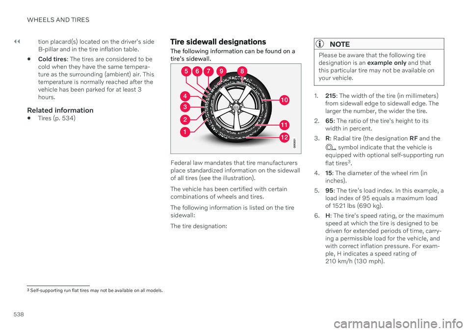
The following information can be found on a tire's sidewall.
Federal law mandates that tire manufacturers place standardized information on the sidewallof all tires (see the illustration). The vehicle has been certified with certain combinations of wheels and tires. The following information is listed on the tire sidewall: The tire designation:
NOTE
Please be aware that the following tire designation is an example only and that
this particular tire may not be available onyour vehicle.
1. 215: The width of the tire (in millimeters)
from sidewall edge to sidewall edge. The larger the number, the wider the tire.
2. 65: The ratio of the tire's height to its
width in percent.
3. R: Radial tire (the designation RF and the
symbol indicate that the vehicle is
equipped with optional self-supporting run flat tires 3
.
4. 15: The diameter of the wheel rim (in
inches).
5. 95: The tire's load index. In this example, a
load index of 95 equals a maximum load of 1521 lbs (690 kg).
6. H: The tire's speed rating, or the maximum
speed at which the tire is designed to bedriven for extended periods of time, carry-ing a permissible load for the vehicle, andwith correct inflation pressure. For exam-ple, H indicates a speed rating of210 km/h (130 mph).
3 Self-supporting run flat tires may not be available on all models.