2021 VOLVO V90 CROSS COUNTRY tow
[x] Cancel search: towPage 555 of 683

WHEELS AND TIRES
}}
553
CAUTION
The vehicle must not be driven with tires of different dimensions or with a spare wheelother than the one that came with the vehi-cle. The use of different size wheels canseriously damage your vehicle's transmis-sion.
Related information
Changing a wheel (p. 548)
Recommended tire pressure (p. 543)
Handling the spare wheel 15
Follow these instructions regarding handling the spare wheel.
Accessing the spare wheel
This illustration is generic and appearance may vary.
The spare tire is located in the spare wheel well under the cargo compartment with theoutside of the wheel facing downward. Thespare tire is secured with a bolt that goesthrough the tire and attaches it to the body.The foam block contains all tools needed tochange a wheel.
1. Lift the rear edge of the cargo compart- ment floor.
2. Unscrew the retaining bolt.
3. Lift out the spare wheel.
Stowing a flat tire1. Screw the spare tire's retaining bolt back on.
CAUTION
Do not attempt to unscrew the lower part of the retaining bolt if it is attached to thebody, as this could cause it to break. If the retaining bolt becomes dislodged from its lower attachment point in thebody under the spare tire, replace it in thehole and turn clockwise to secure it again.
WARNING
On vehicles with 48 V batteries, the bolt is attached to the battery box instead of thebody. If the lower part of the retaining boltis not dislodged when the spare tire istaken out, it should be removed to helpprevent injury when the flat tire is replaced.
2. Put the tools back in their correct posi- tions in the foam block.
3. Then lower the trunk/cargo compartment floor and place the punctured tire in the trunk/cargo compartment.
15Not available on all models.
Page 558 of 683
WHEELS AND TIRES
556
Tire sealing system16
The temporary tire sealing system can be used to seal a puncture in a tire or to checkand adjust the pressure in the tire. Models equipped with a spare wheel 17
do not
have the tire sealing system.
WARNING
California Proposition 65 Operating, servicing and maintaining a pas- senger vehicle can expose you to chemi-cals including engine exhaust, carbon mon-oxide, phthalates, and lead, which areknown to the State of California to causecancer and birth defects or other reproduc-tive harm. To minimize exposure, avoidbreathing exhaust, do not idle the engineexcept as necessary, service your vehicle ina well ventilated area and wear gloves orwash your hands frequently when servicingyour vehicle. For more information go towww.P65Warnings.ca.gov/passenger-vehicle.
The tire sealing system consists of a compres- sor and a bottle containing sealing compound.The sealing functions as a temporary repair.
NOTE
The sealing compound effectively seals tires with punctures in the tread but maynot be able to fully seal tires with punctu-res in the sidewall. Do not use the tire seal-ing system on tires with large tears, cracksor similar damage.
NOTE
The compressor is intended for temporary tire sealing and is approved by Volvo.
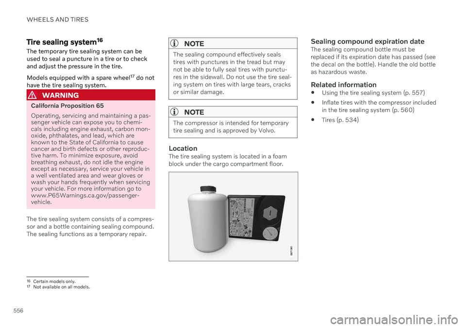
LocationThe tire sealing system is located in a foam block under the cargo compartment floor.
Sealing compound expiration dateThe sealing compound bottle must be replaced if its expiration date has passed (seethe decal on the bottle). Handle the old bottleas hazardous waste.
Related information
Using the tire sealing system (p. 557)
Inflate tires with the compressor includedin the tire sealing system (p. 560)
Tires (p. 534)
16
Certain models only.
17 Not available on all models.
Page 561 of 683
WHEELS AND TIRES
}}
559
8. Start the compressor by moving the
switch to the I (On) position.
When the compressor starts, the pressure
can increase up to 6 bar (88 psi), but thepressure will decrease afterapprox. 30 seconds.
WARNING
Never stand next to a tire being inflated with the compressor. If cracks, bulges, etc.form on the tire, switch off the compressorimmediately. The vehicle should not bedriven. Call roadside assistance to have thevehicle towed to a workshop for inspec-tion/replacement of the tire. Volvo recom-mends an authorized workshop.
9. Inflate the tire for 7 minutes.
CAUTION
To help avoid overheating, the compressor should never be used for more than10 minutes at a time.
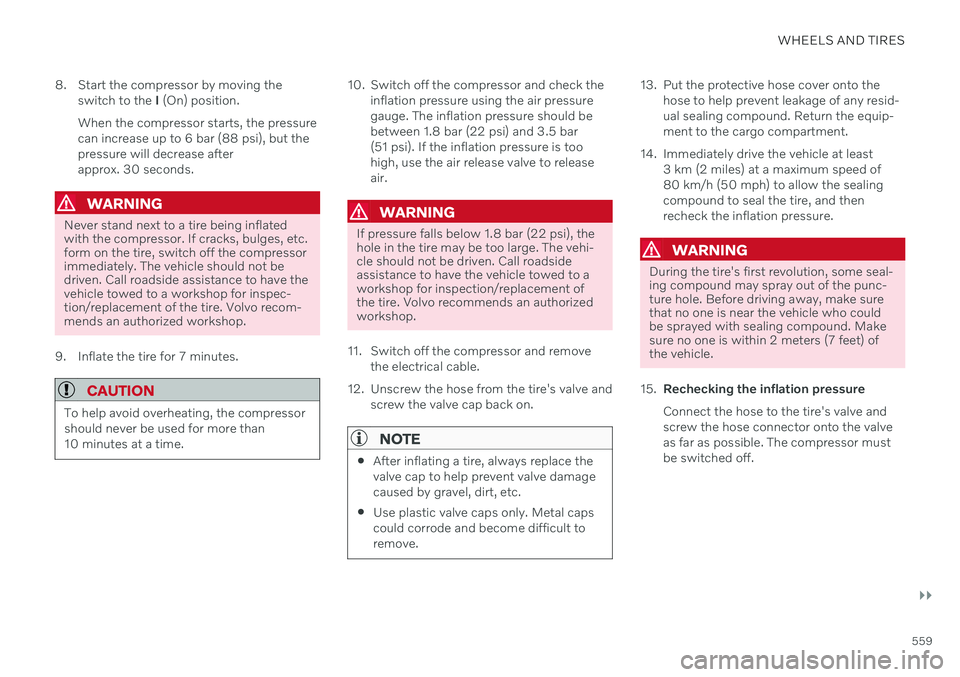
10. Switch off the compressor and check the inflation pressure using the air pressure gauge. The inflation pressure should bebetween 1.8 bar (22 psi) and 3.5 bar(51 psi). If the inflation pressure is toohigh, use the air release valve to releaseair.
WARNING
If pressure falls below 1.8 bar (22 psi), the hole in the tire may be too large. The vehi-cle should not be driven. Call roadsideassistance to have the vehicle towed to aworkshop for inspection/replacement ofthe tire. Volvo recommends an authorizedworkshop.
11. Switch off the compressor and remove the electrical cable.
12. Unscrew the hose from the tire's valve and screw the valve cap back on.
NOTE
After inflating a tire, always replace the valve cap to help prevent valve damagecaused by gravel, dirt, etc.
Use plastic valve caps only. Metal capscould corrode and become difficult toremove.
13. Put the protective hose cover onto the
hose to help prevent leakage of any resid- ual sealing compound. Return the equip-ment to the cargo compartment.
14. Immediately drive the vehicle at least 3 km (2 miles) at a maximum speed of80 km/h (50 mph) to allow the sealingcompound to seal the tire, and thenrecheck the inflation pressure.
WARNING
During the tire's first revolution, some seal- ing compound may spray out of the punc-ture hole. Before driving away, make surethat no one is near the vehicle who couldbe sprayed with sealing compound. Makesure no one is within 2 meters (7 feet) ofthe vehicle.
15. Rechecking the inflation pressure Connect the hose to the tire's valve and screw the hose connector onto the valveas far as possible. The compressor mustbe switched off.
Page 562 of 683
||
WHEELS AND TIRES
56016. Check the inflation pressure on the air
pressure gauge.
If the pressure is under 1.3 bar (19 psi), the tire is not sufficiently sealed. Thevehicle should not be driven. Call road-side assistance to have the vehicletowed.
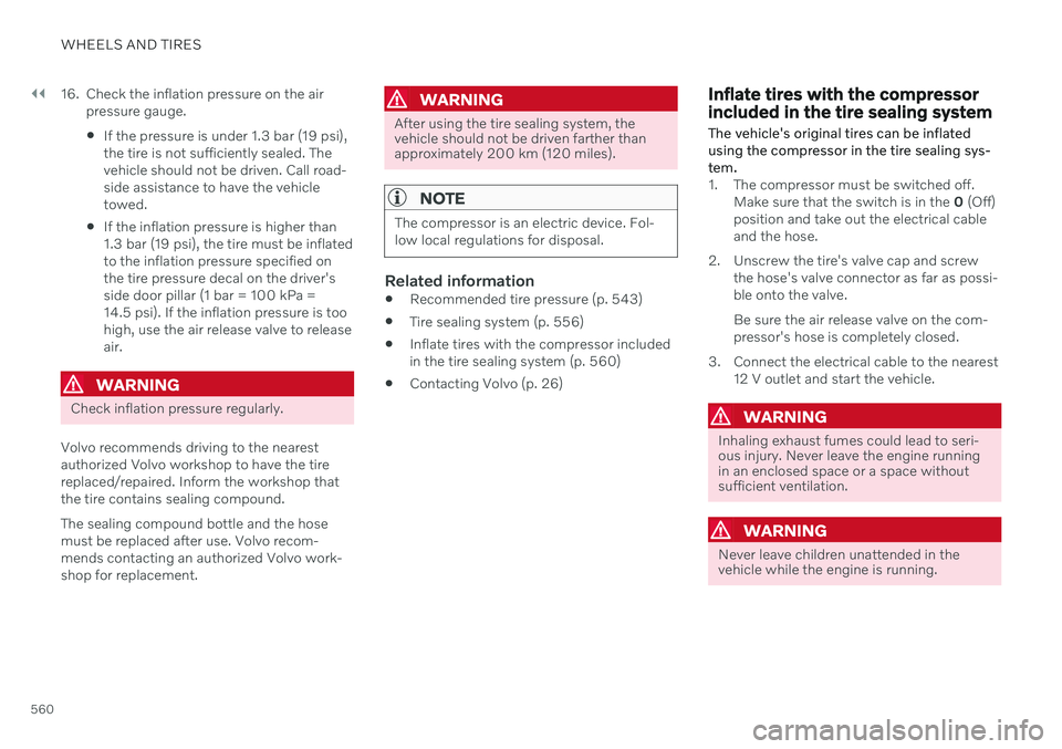
If the inflation pressure is higher than1.3 bar (19 psi), the tire must be inflatedto the inflation pressure specified onthe tire pressure decal on the driver'sside door pillar (1 bar = 100 kPa =14.5 psi). If the inflation pressure is toohigh, use the air release valve to releaseair.
WARNING
Check inflation pressure regularly.
Volvo recommends driving to the nearest authorized Volvo workshop to have the tirereplaced/repaired. Inform the workshop thatthe tire contains sealing compound. The sealing compound bottle and the hose must be replaced after use. Volvo recom-mends contacting an authorized Volvo work-shop for replacement.
WARNING
After using the tire sealing system, the vehicle should not be driven farther thanapproximately 200 km (120 miles).
NOTE
The compressor is an electric device. Fol- low local regulations for disposal.
Related information
Recommended tire pressure (p. 543)
Tire sealing system (p. 556)
Inflate tires with the compressor included in the tire sealing system (p. 560)
Contacting Volvo (p. 26)
Inflate tires with the compressor included in the tire sealing system
The vehicle's original tires can be inflated using the compressor in the tire sealing sys-tem.
1. The compressor must be switched off. Make sure that the switch is in the 0 (Off)
position and take out the electrical cable and the hose.
2. Unscrew the tire's valve cap and screw the hose's valve connector as far as possi-ble onto the valve. Be sure the air release valve on the com- pressor's hose is completely closed.
3. Connect the electrical cable to the nearest 12 V outlet and start the vehicle.
WARNING
Inhaling exhaust fumes could lead to seri- ous injury. Never leave the engine runningin an enclosed space or a space withoutsufficient ventilation.
WARNING
Never leave children unattended in the vehicle while the engine is running.
Page 563 of 683
WHEELS AND TIRES
}}
561
4. Start the compressor by moving the
switch to the I (On) position.
CAUTION
Risk of overheating. The compressor should not be running for longer than 10minutes at a time.
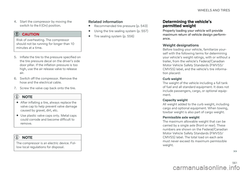
5. Inflate the tire to the pressure specified on
the tire pressure decal on the driver's side door pillar. If the inflation pressure is toohigh, use the air release valve to releaseair.
6. Switch off the compressor. Remove the hose and the electrical cable.
7. Screw the valve cap back onto the tire.
NOTE
After inflating a tire, always replace the valve cap to help prevent valve damagecaused by gravel, dirt, etc.
Use plastic valve caps only. Metal capscould corrode and become difficult toremove.
NOTE
The compressor is an electric device. Fol- low local regulations for disposal.
Related information
Recommended tire pressure (p. 543)
Using the tire sealing system (p. 557)
Tire sealing system (p. 556)
Determining the vehicle's permitted weight
Properly loading your vehicle will provide maximum return of vehicle design perform-ance.
Weight designationsBefore loading your vehicle, familiarize your- self with the following terms for determiningyour vehicle's weight ratings, with or without atrailer, from the vehicle's Federal/CanadianMotor Vehicle Safety Standards (FMVSS/CMVSS) label, and the vehicle's tire informa-tion placard:
Curb weight
The weight of the vehicle including a full tank of fuel and all standard equipment. It does notinclude passengers, cargo, or optional equip-ment.
Capacity weight
All weight added to the curb weight, including cargo and optional equipment. When towing,towbar weight is also part of cargo weight.
Permissible axle weight
The maximum allowable weight that can be carried by a single axle (front or rear). Thesenumbers are shown on the Federal/CanadianMotor Vehicle Safety Standards (FMVSS/CMVSS) label. The total load on each axlemust never exceed its maximum permissibleweight.
Page 564 of 683
||
WHEELS AND TIRES
562
Gross vehicle weight (GVW)
The vehicle's curb weight + cargo + passen- gers.
Steps for Determining Correct Load
Limit
1. Locate the statement "the combined weight of occupants and cargo shouldnever exceed XXX kg or XXX lbs." on yourvehicle's placard.
2. Determine the combined weight of the driver and passengers that will be riding inyour vehicle.
3. Subtract the combined weight of the driver and passengers from XXX kg or XXXlbs.
4. The resulting figure equals the available amount of cargo and luggage loadcapacity. For example, if the "XXX"amount equals 1400 lbs. and there will befive 150 lb. passengers in your vehicle, theamount of available cargo and luggageload capacity is 650 lbs. (1400 - 750 (5 ×150) = 650 lbs.)
5. Determine the combined weight of lug- gage and cargo being loaded on the vehi-cle. That weight may not safely exceed theavailable cargo and luggage load capacitycalculated in Step 4. 6. If your vehicle will be towing a trailer, load
from your trailer will be transferred to yourvehicle. Consult this manual to determinehow this reduces the available cargo andluggage load capacity of your vehicle.WARNING
Exceeding the permissible axle weight, gross vehicle weight, or any otherweight rating limits can cause tire over-heating resulting in permanent defor-mation or catastrophic failure.
Do not use replacement tires withlower load carrying capacities than thetires that were original equipment onthe vehicle because this will lower thevehicle's GVW rating. Use only tireswith the correct load carrying capacity.Consult your Volvo retailer for informa-tion.
Related information
Loading recommendations (p. 570)
Page 571 of 683
LOADING, STORAGE AND PASSENGER COMPARTMENT
* Option/accessory.569
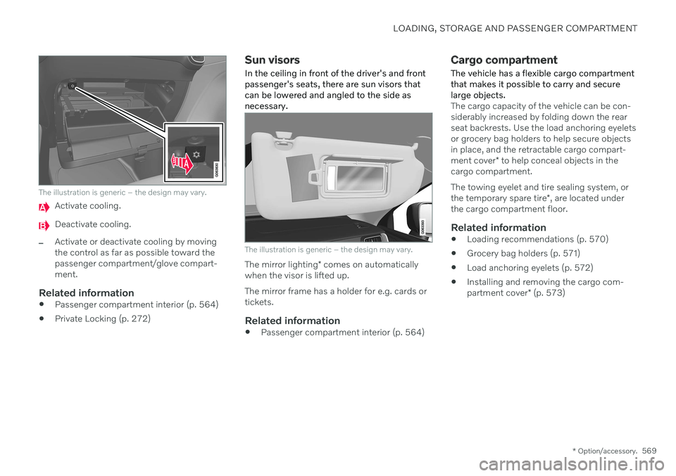
The illustration is generic – the design may vary.
Activate cooling.
Deactivate cooling.
–Activate or deactivate cooling by moving the control as far as possible toward thepassenger compartment/glove compart-ment.
Related information
Passenger compartment interior (p. 564)
Private Locking (p. 272)
Sun visors
In the ceiling in front of the driver's and front passenger's seats, there are sun visors thatcan be lowered and angled to the side asnecessary.
The illustration is generic – the design may vary.
The mirror lighting * comes on automatically
when the visor is lifted up. The mirror frame has a holder for e.g. cards or tickets.
Related information
Passenger compartment interior (p. 564)
Cargo compartment
The vehicle has a flexible cargo compartment that makes it possible to carry and securelarge objects.
The cargo capacity of the vehicle can be con- siderably increased by folding down the rearseat backrests. Use the load anchoring eyeletsor grocery bag holders to help secure objectsin place, and the retractable cargo compart- ment cover * to help conceal objects in the
cargo compartment. The towing eyelet and tire sealing system, or the temporary spare tire *, are located under
the cargo compartment floor.
Related information
Loading recommendations (p. 570)
Grocery bag holders (p. 571)
Load anchoring eyelets (p. 572)
Installing and removing the cargo com-partment cover
* (p. 573)
Page 573 of 683
LOADING, STORAGE AND PASSENGER COMPARTMENT
}}
571
Roof loads and load carriers
Volvo-developed load carriers are recom- mended for carrying loads on the roof of thevehicle.
Volvo load carriers are specially designed to help prevent damage to your vehicle and helpensure maximum safety while driving. Volvoload carriers are available from authorizedVolvo retailers. Carefully follow the installation instructions provided with the load carriers. Distribute the load evenly throughout the load carriers. Place heavier cargo at thebottom of the load.
Check periodically to ensure that the loadcarriers and load are properly secured.Secure the load firmly using tie straps orsimilar.
If the load is longer than the vehicle, suchas a canoe or kayak, attach the towingeyelet in its front outlet and secure the tiestraps in it.
The vehicle's wind resistance and fuelconsumption increase with the size of theload.
Drive smoothly. Avoid rapid acceleration,hard braking and fast cornering.
WARNING
The vehicle's center of gravity and driving characteristics are altered by roof loads. Follow the vehicle's specifications regar- ding weights and maximum permittedload.
Related information
Loading recommendations (p. 570)
Weights (p. 655)
Grocery bag holders Grocery bag holders (hooks) help keep shop- ping bags in place and prevent them fromfalling over and spilling their contents in thecargo compartment.
On the sides of the cargo compartment
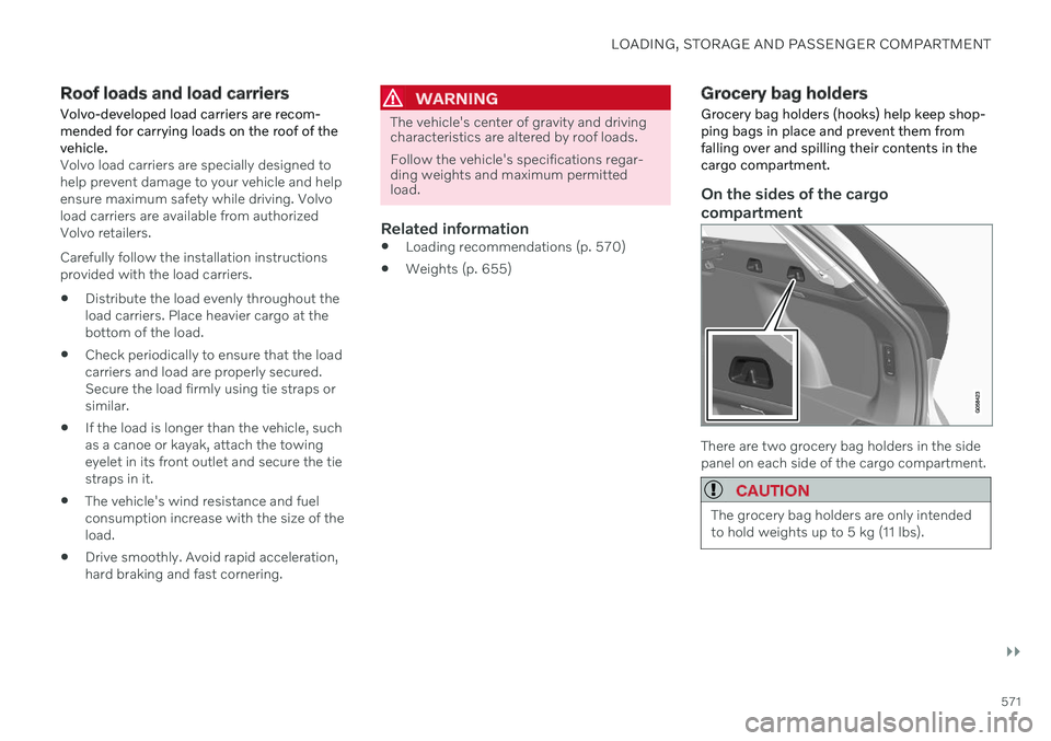
There are two grocery bag holders in the side panel on each side of the cargo compartment.
CAUTION
The grocery bag holders are only intended to hold weights up to 5 kg (11 lbs).