2021 VOLVO V90 CROSS COUNTRY weight
[x] Cancel search: weightPage 83 of 683
SAFETY
}}
81
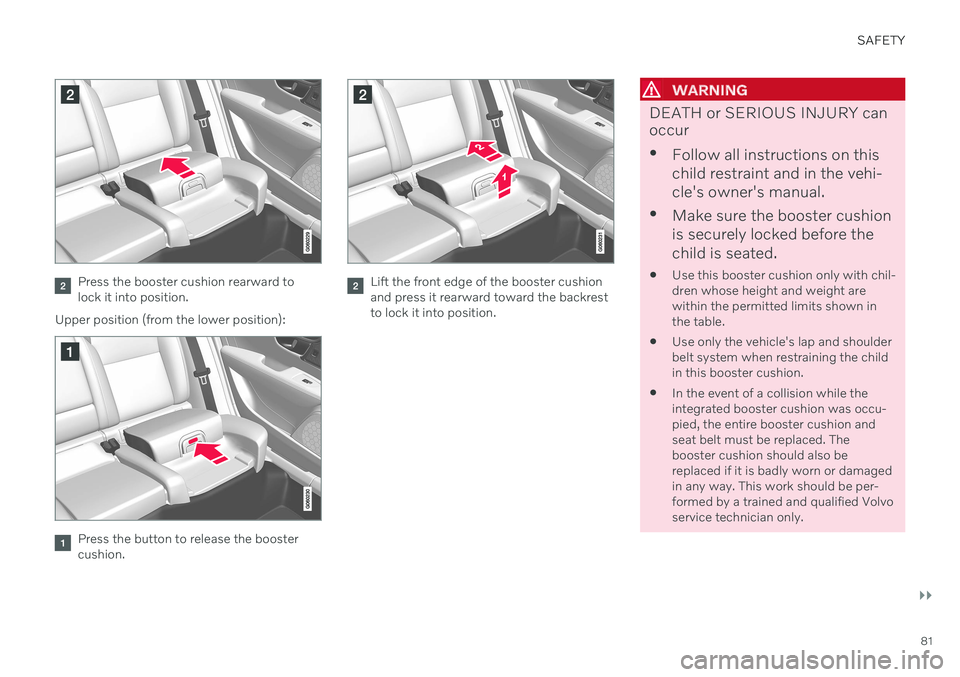
Press the booster cushion rearward to lock it into position.
Upper position (from the lower position):
Press the button to release the booster cushion.
Lift the front edge of the booster cushion and press it rearward toward the backrestto lock it into position.
WARNING
DEATH or SERIOUS INJURY can occur Follow all instructions on this child restraint and in the vehi-cle's owner's manual.
Make sure the booster cushionis securely locked before thechild is seated.
Use this booster cushion only with chil- dren whose height and weight arewithin the permitted limits shown inthe table.
Use only the vehicle's lap and shoulderbelt system when restraining the childin this booster cushion.
In the event of a collision while theintegrated booster cushion was occu-pied, the entire booster cushion andseat belt must be replaced. Thebooster cushion should also bereplaced if it is badly worn or damagedin any way. This work should be per-formed by a trained and qualified Volvoservice technician only.
Page 85 of 683
SAFETY
* Option/accessory.83
WARNING
DEATH or SERIOUS INJURY can occur
Follow all instructions on this child restraint and in the vehi-cle's owner's manual.
Make sure the booster cushionis securely locked before thechild is seated.
Use this booster cushion only with chil- dren whose height and weight arewithin the permitted limits shown inthe table.
Use only the vehicle's lap and shoulderbelt system when restraining the childin this booster cushion.
In the event of a collision while theintegrated booster cushion was occu-pied, the entire booster cushion andseat belt must be replaced. Thebooster cushion should also bereplaced if it is badly worn or damagedin any way. This work should be per-formed by a trained and qualified Volvoservice technician only.
Related information
Integrated booster cushion
* (p. 79)
Folding up the integrated booster cush- ion
* (p. 80)
Page 448 of 683
STARTING AND DRIVING
446
Selecting ignition mode (p. 402)
Support battery (p. 602)
Driving with a trailer
There are a number of things to consider when towing a trailer, such as the towbar, thetrailer and how the load is distributed in thetrailer.
Load-carrying capacity is determined by the vehicle's curb weight. The total weight of allpassengers and any installed accessories, e.g.towbar, reduces the vehicle's load-carryingcapacity by the corresponding amount.
Towbars used on the vehicle must beapproved for the applicable use.
Distribute the load on the trailer so thatthe weight on the towbar complies withthe specified maximum towball weight.The tongue weight is calculated as part ofthe vehicle's payload.
Increase the tire pressure to the recom-mended pressure for a full load.
The engine is subjected to more load thanusual when towing a trailer.
Towing a trailer affects the vehicle's han-dling, durability and driving economy.
Do not drive with a heavy trailer when thevehicle is very new. Wait until the mileagehas reached at least 1000 km (620 miles).
On long and steep downgrades, the vehi-cle's brakes are subjected to much moreload than usual. When manually shifting, downshift and adapt speed accordingly.
Follow applicable regulations regarding permitted speed and weight.
Drive slowly when towing a trailer up along and steep incline.
The maximum trailer weights given onlyapply to altitudes up to 1000 meters(3280 feet) above sea level. At higher alti-tudes, engine power (and thus the vehi-cle's climbing ability) is decreased due tothe reduced air density, and the maximumtrailer weight must therefore be reduced.The weight of the vehicle and trailer mustbe decreased by 10% for each additional1000 m (3280 feet) or part thereof.
Avoid driving with a trailer on inclines ofmore than 12%.
Avoid overloading and other incorrect use.
The trailer's brakes must be balanced withthe vehicle's brakes to help ensure safestops (follow applicable local regulations).
Page 449 of 683
STARTING AND DRIVING
}}
* Option/accessory.447
CAUTION
Bumper-attached trailer hitches must not be used on Volvos, nor shouldsafety chains be attached to thebumper.
Trailer hitches attaching to the vehiclerear axle must not be used.
Never connect a trailer's hydraulicbrake system directly to the vehiclebrake system, nor a trailer's lightingsystem directly to the vehicle lightingsystem. Consult your nearest author-ized Volvo retailer for correct installa-tion.
When towing a trailer, the trailer'ssafety chains or wire must be correctlyfastened to the attachment points pro-vided in the trailer hitch on the vehicle.The safety chain or wire must never befastened to or wound around the tow-ing ball.
NOTE
The optional detachable trailer hitch may not be available in all markets or on allmodels. Consult your Volvo retailer.
NOTE
Extreme weather conditions, towing a trailer, high altitude and lower fuel gradethan recommended are factors that cansignificantly increase the vehicle's fuel con-sumption.
Trailer weights
WARNING
Please adhere to the recommendations provided for trailer weight. If the recom-mendations are not followed, the vehicleand trailer may be difficult to control duringevasive maneuvers and braking.
NOTE
The specified maximum trailer weights are those permitted by Volvo. National vehicleregulations may set additional restrictionson trailer weight and speed. The trailerhitches may be certified for higher towingweights than the vehicle is permitted totow.
Self-leveling suspension
*The vehicle's self-leveling system attempts to keep the vehicle at a constant level, regardlessof load (up to the maximum permitted weight).When the vehicle is stationary, the rear end of the vehicle will be slightly lowered, which isnormal.
Driving in hilly terrain or hot weatherIn certain conditions, there is a risk of over-heating when driving with a trailer. If overheat-ing of the engine and drive system is detected,a warning symbol will illuminate in the instru-ment panel and a message will appear. The automatic transmission adapts the gear for the current load and engine speed.
Steep inclines
Do not lock the automatic transmission into a higher gear than what the engine can handle
‒
it is not always preferable to drive in highgears at low rpm.
Parking on a hill
1. Depress the brake pedal.
2. Apply the parking brake.
3. Put the gear selector in P.
4. Release the brake pedal.Put chocks behind the wheels when the vehi- cle is parked on a hill with a trailer attached.
Starting on a hill
1. Depress the brake pedal.
2. Put the gear selector in D.
3. Release the parking brake.
4. Release the brake pedal and start driving.
Page 450 of 683
||
STARTING AND DRIVING
* Option/accessory.
448
Related information
Trailer Stability Assist
* (p. 448)
Checking trailer lights (p. 449)
Towing capacity and tongue weight (p. 656)
Overheating of engine and transmission(p. 442)
Trailer Stability Assist
*
Trailer Stability Assist (TSA 23
) is part of the
ESC 24
stability system and is a function
designed to help stabilize a vehicle that is towing a trailer when the vehicle and trailerhave begun to sway. The function is addedwhen installing a towbar. Contact a Volvoretailer for more information.
Reasons for swayingA vehicle towing a trailer may begin to sway for various reasons. Normally this only occursat high speeds. However, if the trailer is over-loaded or unevenly distributed, e.g. too farback, there is a risk of swaying even at lowspeeds. Swaying may be caused by factors such as:
The vehicle and trailer are hit by a sudden, strong crosswind.
The vehicle and trailer are traveling on anuneven road or over a bump.
Sudden movements of the steering wheel.
Once swaying has begun, it can be difficult orimpossible to stop it. This makes the vehicleand trailer difficult to control and there is a riskof swerving into oncoming traffic or driving offthe road.
Trailer Stability Assist functionTrailer Stability Assist continuously monitorsthe vehicle's movements, particularly lateralmovements. If swaying is detected, the brakesare applied individually on the front wheels,which has a stabilizing effect on the vehicleand trailer. This is often enough to enable thedriver to regain control of the vehicle. If the Trailer Stability Assist function's first attempt is not adequate to stop the swayingmotion, the brakes are applied on all wheelsand engine power is temporarily reduced. Asthe swaying motion begins to decrease andthe vehicle and trailer have once againbecome stable, TSA stops regulating thebrakes/engine power and the driver regainscontrol of the vehicle.
NOTE
Trailer Stability Assist is deactivated if the driver activates ESC Sport Mode in the
center display's menu system.
Trailer Stability Assist may not intervene if the driver tries to compensate for the swayingmotion by moving the steering wheel rapidly,because the system will then not be able todetermine if it is the trailer or the driver caus-ing the swaying.
23 Trailer Stability Assist
24 Electronic Stability Control
Page 539 of 683
WHEELS AND TIRES
}}
537
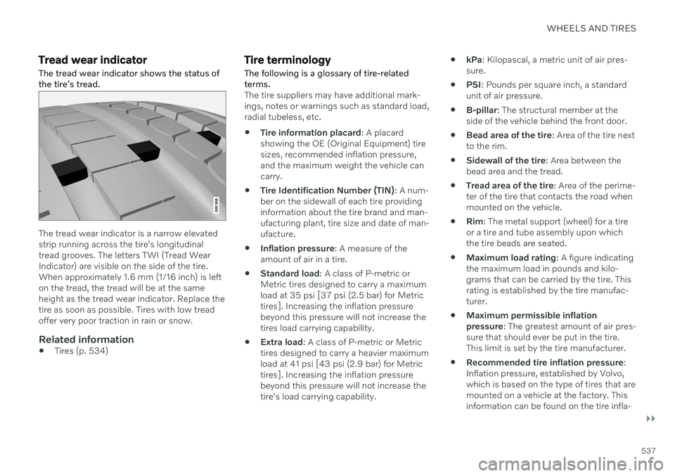
Tread wear indicatorThe tread wear indicator shows the status of the tire's tread.
The tread wear indicator is a narrow elevated strip running across the tire's longitudinaltread grooves. The letters TWI (Tread WearIndicator) are visible on the side of the tire.When approximately 1.6 mm (1/16 inch) is lefton the tread, the tread will be at the sameheight as the tread wear indicator. Replace thetire as soon as possible. Tires with low treadoffer very poor traction in rain or snow.
Related information
Tires (p. 534)
Tire terminology
The following is a glossary of tire-related terms.
The tire suppliers may have additional mark- ings, notes or warnings such as standard load,radial tubeless, etc.
Tire information placard
: A placard
showing the OE (Original Equipment) tiresizes, recommended inflation pressure,and the maximum weight the vehicle cancarry.
Tire Identification Number (TIN)
: A num-
ber on the sidewall of each tire providinginformation about the tire brand and man-ufacturing plant, tire size and date of man-ufacture.
Inflation pressure
: A measure of the
amount of air in a tire.
Standard load
: A class of P-metric or
Metric tires designed to carry a maximumload at 35 psi [37 psi (2.5 bar) for Metrictires]. Increasing the inflation pressurebeyond this pressure will not increase thetires load carrying capability.
Extra load
: A class of P-metric or Metric
tires designed to carry a heavier maximumload at 41 psi [43 psi (2.9 bar) for Metrictires]. Increasing the inflation pressurebeyond this pressure will not increase thetire's load carrying capability.
kPa
: Kilopascal, a metric unit of air pres-
sure.
PSI
: Pounds per square inch, a standard
unit of air pressure.
B-pillar
: The structural member at the
side of the vehicle behind the front door.
Bead area of the tire
: Area of the tire next
to the rim.
Sidewall of the tire
: Area between the
bead area and the tread.
Tread area of the tire
: Area of the perime-
ter of the tire that contacts the road whenmounted on the vehicle.
Rim
: The metal support (wheel) for a tire
or a tire and tube assembly upon whichthe tire beads are seated.
Maximum load rating
: A figure indicating
the maximum load in pounds and kilo-grams that can be carried by the tire. Thisrating is established by the tire manufac-turer.
Maximum permissible inflationpressure
: The greatest amount of air pres-
sure that should ever be put in the tire.This limit is set by the tire manufacturer.
Recommended tire inflation pressure
:
Inflation pressure, established by Volvo,which is based on the type of tires that aremounted on a vehicle at the factory. Thisinformation can be found on the tire infla-
Page 563 of 683
WHEELS AND TIRES
}}
561
4. Start the compressor by moving the
switch to the I (On) position.
CAUTION
Risk of overheating. The compressor should not be running for longer than 10minutes at a time.
5. Inflate the tire to the pressure specified on
the tire pressure decal on the driver's side door pillar. If the inflation pressure is toohigh, use the air release valve to releaseair.
6. Switch off the compressor. Remove the hose and the electrical cable.
7. Screw the valve cap back onto the tire.
NOTE
After inflating a tire, always replace the valve cap to help prevent valve damagecaused by gravel, dirt, etc.
Use plastic valve caps only. Metal capscould corrode and become difficult toremove.
NOTE
The compressor is an electric device. Fol- low local regulations for disposal.
Related information
Recommended tire pressure (p. 543)
Using the tire sealing system (p. 557)
Tire sealing system (p. 556)
Determining the vehicle's permitted weight
Properly loading your vehicle will provide maximum return of vehicle design perform-ance.
Weight designationsBefore loading your vehicle, familiarize your- self with the following terms for determiningyour vehicle's weight ratings, with or without atrailer, from the vehicle's Federal/CanadianMotor Vehicle Safety Standards (FMVSS/CMVSS) label, and the vehicle's tire informa-tion placard:
Curb weight
The weight of the vehicle including a full tank of fuel and all standard equipment. It does notinclude passengers, cargo, or optional equip-ment.
Capacity weight
All weight added to the curb weight, including cargo and optional equipment. When towing,towbar weight is also part of cargo weight.
Permissible axle weight
The maximum allowable weight that can be carried by a single axle (front or rear). Thesenumbers are shown on the Federal/CanadianMotor Vehicle Safety Standards (FMVSS/CMVSS) label. The total load on each axlemust never exceed its maximum permissibleweight.
Page 564 of 683
||
WHEELS AND TIRES
562
Gross vehicle weight (GVW)
The vehicle's curb weight + cargo + passen- gers.
Steps for Determining Correct Load
Limit
1. Locate the statement "the combined weight of occupants and cargo shouldnever exceed XXX kg or XXX lbs." on yourvehicle's placard.
2. Determine the combined weight of the driver and passengers that will be riding inyour vehicle.
3. Subtract the combined weight of the driver and passengers from XXX kg or XXXlbs.
4. The resulting figure equals the available amount of cargo and luggage loadcapacity. For example, if the "XXX"amount equals 1400 lbs. and there will befive 150 lb. passengers in your vehicle, theamount of available cargo and luggageload capacity is 650 lbs. (1400 - 750 (5 ×150) = 650 lbs.)
5. Determine the combined weight of lug- gage and cargo being loaded on the vehi-cle. That weight may not safely exceed theavailable cargo and luggage load capacitycalculated in Step 4. 6. If your vehicle will be towing a trailer, load
from your trailer will be transferred to yourvehicle. Consult this manual to determinehow this reduces the available cargo andluggage load capacity of your vehicle.WARNING
Exceeding the permissible axle weight, gross vehicle weight, or any otherweight rating limits can cause tire over-heating resulting in permanent defor-mation or catastrophic failure.
Do not use replacement tires withlower load carrying capacities than thetires that were original equipment onthe vehicle because this will lower thevehicle's GVW rating. Use only tireswith the correct load carrying capacity.Consult your Volvo retailer for informa-tion.
Related information
Loading recommendations (p. 570)