Page 314 of 502
Removing the ball head
First read and observe the introductoryinformation and safety warnings⇒Introduction
⇒ Electronic parking brake .
ailer and disconnect the electrical connection between the vehicle and the trailer.
If fitted, remove adapters from the trailer socket.
⇒ Fig. 155 ⑧ from the lock in the locking lever and insert the key ⑦ into
the lock.
e key ⑦ anti-clockwise until the part of the key with the hole is at the top.
② with your hand.
⑨ and at the same time press the locking lever ⑥ down as far as it will go
⇒ . The ball head is pre-tensioned.
⑥ and stow the pre-tensioned ball head safely with the vehicle toolkit.
② with your hand.
damage to the mounting.
WARNING
The removable ball head is heavy. The ball head could fall while it is being removed. This could cause
injuries.
Notes on towing a trailer
Page 315 of 502

Fig. 156 Pin assignment for the trailer socket (illustration).
First read and observe the introductoryinformation and safety warnings⇒Introduction
Pin assignment for the trailer socket ⇒ Fig. 156 :
Left turn signal
Rear fog light
Earth for pins 1, 2, 4, 5, 6, 7, 8
Right turn signal
Tail light, right
Brake light
Tail light, left
Reversing light
Permanent positive
Permanent positive
Earth for pin 10
Not assigned
Earth for pin 9
Trailer socket
A 13-pin trailer socket produces the electrical connection between the towing vehicle and the trailer.
When the vehicle electrically detects a trailer, the consumers in the trailer are supplied with an
electrical voltage via the electrical connection (pins 9 and 10). Pin 9 is assigned as the permanent
positive, enabling operation of the trailer interior lighting, for example.
Electrical consumers such as a caravan refrigerator are supplied with power only when the engine is
running (pin 10).
To avoid overloading the electrical system, do not connect the earth wires (pins 3, 11 and 13) with
each other.
If the trailer has a 7-pin plug you will need to use a suitable adapter cable. The function of pin 10 is
then not available.
Page 318 of 502

possible.
Tyre pressure
Follow the trailer manufacturer's recommendations concerning the tyre pressure for the trailer
tyres.
When towing a trailer, inflate the wheels on the towing vehicle with the maximum permitted tyre
pressure ⇒ Tyre pressure .
WARNING
Accidents and serious injuries can occur if you exceed the vehicle's maximum permitted gross axle
weight rating, drawbar load, gross vehicle weight rating or gross combination weight rating.
exceed the permissible gross vehicle weight for the vehicle with weight at the front and rear of the
vehicle.
WARNING
Loads that may slide can severely impair stability and driving safety, which can cause accidents and
severe injuries.
secure loads using suitable and undamaged lashing, retaining or securing straps.
Driving with a trailer
First read and observe the introductoryinformation and safety warnings⇒Introduction
Headlight adjustment
Towing a trailer can raise the front end of the vehicle enough for the dipped beam to dazzle other
road users. Use the headlight range control to lower the light cone as required. Vehicles with
dynamic headlight range control are adjusted automatically.
Things to note when driving with a trailer
If the trailer has an overrun brake, apply the brakes gently at first and then firmly. This will
prevent the jerking that can be caused by the trailer wheels locking.
Page 319 of 502

prior to downhill gradients (manual gearbox or Tiptronic mode of the
automatic gearbox) to additionally make use of engine braking. The brake system could otherwise
overheat and fail.
will change because of the
trailer load and the increased combined towing weight of the vehicle and trailer.
When driving with this combination, drive particularly carefully and slowly.
Pulling off on slopes when towing a trailer
Depending on the steepness of the uphill gradient and the total weight of the trailer and vehicle, a
vehicle towing a trailer could roll back a short distance when moving off on a hill.
When towing a trailer, pull off on slopes as follows:
once to switch off the electronic parking brake ⇒ Electronic parking brake .
ly.
⇒ Manual gearbox: selecting a gear or selector lever position D/S⇒ DSG® dual
clutch gearbox .
button and hold it in this position to hold the vehicle and trailer with the electronic
parking brake.
ake pedal.
button only when the engine has sufficient power to move off.
WARNING
Incorrect trailer towing can cause loss of vehicle control and serious personal injury.
and increase the braking distance.
pt your speed and driving style to suit visibility, weather, road and traffic conditions.
Reduce your speed, particularly when going downhill.
care when overtaking. Reduce your speed immediately if the trailer shows even the
slightest sign of snaking.
Page 340 of 502

First read and observe the introductoryinformation and safety warnings⇒Introduction
Checklist
Always carry out the following actions for changing a bulb in the given order ⇒ :
Park the vehicle on a firm and level surface at a safe distance from the flow of traffic.
Switch on the electronic parking brake Electronic parking brake.
Turn the light switch to position 0 Switching lights on and off.
Move the turn signal and main beam lever to neutral position Switching turn signals on and off.
Automatic gearbox: move the selector lever to position P DSG® dual clutch gearbox.
Stop the engine and remove the vehicle key from the ignition Starting the engine.
Manual gearbox: select a gear Manual gearbox: selecting a gear.
Allow the orientation lighting to go out Coming Home and Leaving Home function (orientation
lighting).
Leave the defective bulbs to cool down.
Check to see if a fuse has visibly blown Changing fuses.
Follow the instructions to change the affected bulb . Always replace bulbs with identical bulbs of the
same type. The designation is inscribed on the bulb, either on the glass part or on the base.
Page 348 of 502
ge compartment into position. Insert brake element into the opening of
the holder and push it upwards until it audibly clicks into place. Carefully push the stowage
compartment forwards beyond the resistance of the catches ⇒ Fig. 171 ②.
NOTICE
e the covers of the fuse boxes carefully and install them again properly so as to avoid
damage to the vehicle.
boxes can damage the electrical system.
Fuses in the engine compartment
Fig. 172 In the engine compartment: cover ① of fuse box with plastic pliers ②.
First read and observe the introductoryinformation and safety warnings⇒Introduction
Opening the fuse box in the engine compartment
et ⇒ In the engine compartment .
⇒ Fig. 172 ① to release the fuse box
cover.
y clicks
into place on both sides.
In some vehicles, there is a pair of plastic pliers ⇒ Fig. 172 ② for removing fuses on the inside of
the cover of the fuse box in the engine compartment.
NOTICE
tall them again properly so as to avoid
damage to the vehicle.
Page 349 of 502

boxes can damage the electrical system.
Fuse table for fuses in the dash panel
Fig. 173 In the dash panel: fuse assignment.
First read and observe the introductoryinformation and safety warnings⇒Introduction
The table shows the fuse locations of the electrical consumers relevant for the driver. The first
column in the table contains the location. The other columns contain the fuse type, the amp rating
and the consumer protected by the fuse.
Depending on the market and specification of your vehicle, the fuse numbers and positions may
differ to those given in the table. If necessary, ask your Volkswagen dealership for the exact fuse
assignment.
Fuse location ⇒ Fig. 173
F410 amps, MINI®, anti-theft alarm.F710 amps, MINI®, air conditioning system control panel or
heating and fresh air system, rear window heating relay.F810 amps, MINI®, light switch (dipped
beam), rain/light sensor, electronic parking brake.F107.5 amps, MINI®, display, Infotainment control
panel.F1140 amps, ATO®, left exterior lighting.F1220 amps, ATO®, Infotainment
components.F1440 amps, ATO®, blower regulator.F167.5 amps, MINI®, telephone.F2215 amps,
ATO®, trailer charging cable.F2330 amps, JCASE®, electric glass roof.F2440 amps, ATO®, right
exterior lighting.F2630 amps, ATO®, seat heating.F2730 amps, ATO®, interior lighting.F2825 amps,
ATO®, left trailer control unit.F3825 amps, ATO®, right trailer control unit.F401)20 amps, ATO®,
cigarette lighter, sockets.F4240 amps, ATO®, central locking.F4415 amps, ATO®, trailer control
unit.F4715 amps, ATO®, rear window wiper.F5125 amps, ATO®, rear seat heating.F5330 amps, ATO®,
rear window heating.
Page 350 of 502

1) Note installation position. Factory-fitted fuse location as shown in illustration ⇒ Fig. 173 .
Fuse tables for fuses in the engine compartment
First read and observe the introductoryinformation and safety warnings⇒Introduction
The table shows the fuse locations of the electrical consumers relevant for the driver. The first
column in the table contains the location. The other columns contain the fuse type, the amp rating
and the consumer protected by the fuse.
Depending on the market and specification of your vehicle, the fuse numbers and positions may
differ to those given in the table. If necessary, ask your Volkswagen dealership for the exact fuse
assignment.
F65 amps, ATO®, brake light sensor.F1440 amps, JCASE®, windscreen heating.F1515 amps, ATO®,
horn.F1930 amps, ATO®, front wipers.F3720 amps, ATO®, auxiliary heater.
Changing a blown fuse
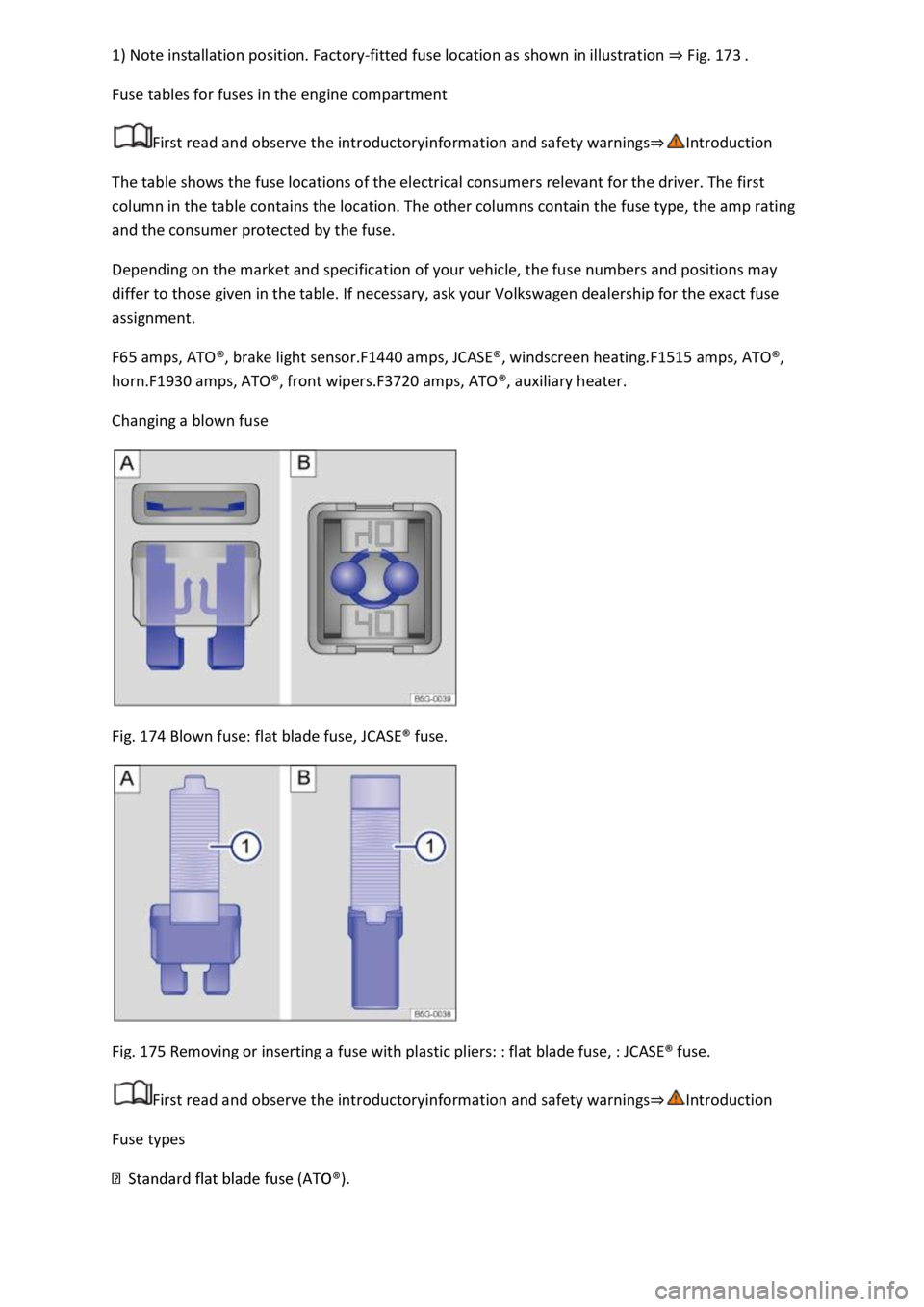
Fig. 174 Blown fuse: flat blade fuse, JCASE® fuse.
Fig. 175 Removing or inserting a fuse with plastic pliers: : flat blade fuse, : JCASE® fuse.
First read and observe the introductoryinformation and safety warnings⇒Introduction
Fuse types