2021 VOLKSWAGEN T-ROC key
[x] Cancel search: keyPage 274 of 502

Fig. 132 On the instrument cluster display: driving out of a parallel parking space.
First read and observe the introductoryinformation and safety warnings⇒Introduction
Key to ⇒ Fig. 132 :
Parked vehicle.
Own vehicle with reverse gear engaged.
Progress bar. Symbolically shows the relative distance still to be driven.
Direction indicator for next manoeuvre for driving out of the parking space.
Park Assist can drive out of parallel parking spaces if the prerequisites for this are met
⇒ Prerequisites .
Press the button.
Use the turn signal lever to select the direction (left or right) in which you would like to drive out of
the parking space.
Select reverse gear.
Release the steering wheel when the following message is shown: Steer. intervention active.
Monitor vehicle area.
Accelerate carefully.
Brake when an acoustic signal sounds, the display lights up or until the prompt to drive forward
appears on the instrument cluster display.
Depress the brake pedal until Park Assist has finished steering or until the display in the
instrument cluster display will go out.
Repeat reversing and driving forwards until a corresponding message is displayed on the instrument
cluster. A signal tone may also sound.
Take over steering with the steering angle set by Park Assist.
Drive the vehicle out of the parking space when permitted by the traffic situation.
Page 277 of 502

Rear Traffic Alert monitors the traffic crossing behind the vehicle when reversing out of a parking
space or manoeuvring. Rear Traffic Alert functions using radar sensors in the rear bumper.
Key to ⇒ Fig. 134 :
Critical situation. Do not drive on!Possible critical situation.
Detection of a critical situation can also take place acoustically:
A warning signal will sound and a text message will be displayed in the instrument cluster for
vehicles without Park Distance Control.
In vehicles with Park Distance Control, an acoustic signal will sound with the continuous tone of Park
Distance Control. If the Park Distance Control is deactivated, no warning can be given to the driver
and the Rear Traffic Alert system will also be switched off temporarily.
If there is a system fault in the scanned area, the indicator lamp will light up yellow on the
instrument cluster display.
Automatic braking intervention to minimise damage
If Rear Traffic Alert detects an approaching road user and the driver has not pressed the brake, the
system can brake automatically.
Automatic braking intervention is activated when reversing at speeds of between 1–12 km/h (1–
7 mph). The vehicle is held stationary for up to two seconds after vehicle standstill has been
detected.
After automatic braking intervention is activated to prevent damage to the vehicle, the system
requires approximately ten seconds before it can activate another automatic braking intervention.
Automatic braking intervention can be interrupted by pressing the accelerator or brake pedal
sharply and taking control of the vehicle.
Automatic deactivation
Rear Traffic Alert is deactivated automatically and cannot be switched on if the factory-fitted towing
bracket is electrically connected to a trailer or similar ⇒ Notes on towing a trailer . Once a trailer is
electrically connected to the vehicle and the driver pulls away, a text message appears in the
instrument cluster display to inform the driver that Rear Traffic Alert has been deactivated. Rear
Traffic Alert will be automatically activated again when the trailer has been unhitched from the
vehicle. This applies if the functions were previously activated. Rear Traffic Alert must be switched
off manually for trailer towing if a non-factory-fitted towing bracket is used.
WARNING
The intelligent Rear Traffic Alert technology cannot overcome the laws of physics, and functions only
within the limits of the system. Do not let the assistance function of Rear Traffic Alert tempt you to
take any safety risks while driving. The system is not a substitute for the full concentration of the
driver.
Page 283 of 502

Before adjusting the seats, always ensure that there is no cigarette lighter on or near the moveable
parts of the seat.
Before closing stowage areas or compartments always ensure that there is no lighter in the way.
Never stow lighters in stowage areas or compartments or on other surfaces in the vehicle. Cigarette
lighters may self-ignite as a result of high surface temperatures, particularly in summer.
NOTICE
The heating elements in the rear window can be destroyed by objects rubbing against them.
Do not stow any temperature-sensitive objects, food or medicines inside the vehicle. Hot and cold
temperatures could damage them or render them unusable.
Objects stored in the vehicle that are made from transparent materials, such as glasses, magnifying
glasses or transparent suction cups on the windows, can concentrate the sun's rays and thus cause
damage to the vehicle.
Always ensure that the ventilation openings between the rear window and the stowage area are
uncovered to allow stale air to escape from the vehicle.
Stowage compartment on the front passenger side
Fig. 135 On the front passenger side: open stowage compartment.
First read and observe the introductoryinformation and safety warnings⇒Introduction
Key to ⇒ Fig. 135 :
Media drives for the Infotainment system, card readers ⇒BookletInfotainment system,.
Mounting for glasses compartment.
Opening and closing the stowage compartment
Page 284 of 502

If necessary, unlock the stowage compartment. The stowage compartment is locked when the key
slot is vertical.
To open: pull the opening lever.
To close: push the stowage compartment upwards.
WARNING
If the stowage compartment on the front passenger side is left open, this can increase the risk of
serious injury in the event of an accident or during sudden braking or driving manoeuvres.
Always keep the stowage compartment closed while the vehicle is in motion.
NOTICE
In some vehicle models, the stowage compartment on the front passenger side contains apertures.
Small items could fall through the apertures and become trapped behind the trim. This could cause
unusual noises and damage to the vehicle.
Stow small objects only in the stowage areas that are intended for such items.
Stowage compartment in the front centre armrest
Fig. 136 In the front centre armrest: stowage compartment.
First read and observe the introductoryinformation and safety warnings⇒Introduction
To open: lift the centre armrest ⇒ Fig. 136 .
To close: guide the centre armrest down.
WARNING
The centre armrest can obstruct the driver's arm movements. This can cause accidents and severe
injuries.
Page 311 of 502

The vehicle electronics system may be damaged if the trailer's power consumption is too high.
Never connect the trailer's electrical system directly to the electrical connections of the tail light
clusters or to other power sources. Use only suitable connectors to supply power to the trailer.
Towing a trailer places additional demands on the vehicle. Volkswagen recommends additional
services between the normal inspection intervals if the vehicle is used frequently for towing a trailer.
Fitting the removable ball head
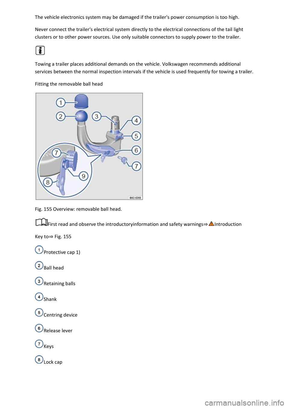
Fig. 155 Overview: removable ball head.
First read and observe the introductoryinformation and safety warnings⇒Introduction
Key to⇒ Fig. 155
Protective cap 1)
Ball head
Retaining balls
Shank
Centring device
Release lever
Keys
Lock cap
Page 312 of 502

Release pin with coloured marking
The removable ball head is located with the vehicle toolkit in the luggage compartment.
Step 1: preparations
Remove the cap from the ball head mounting under the rear bumper ⇒ Rear view and stow in the
vehicle.
Starting from the bottom right side, swivel the trailer socket as far as possible to the top left. This
gives you access to the ball head mounting.
Check to ensure that the mounting, locking lever ⇒ Fig. 155 ⑥, shank ④ and the retaining balls
③ of the ball head are all clean and not damaged ⇒ . Clean if necessary.
Step 2: check whether the ball head is pre-tensioned
The ball head cannot be fitted properly unless it is pre-tensioned.
The following conditions must be fulfilled:
The lock cover ⇒ Fig. 155 ⑧ is open and the key ⑦ is inserted
The release pin ⑨ can be moved.
The locking lever ⑥ is in the bottom position.
All retaining balls ③ can be pressed fully into the shank ④.
If all these conditions are met, continue with Step 4.
If conditions are not met, continue with Step 3.
Step 3: pre-tensioning the ball head
If the ball head is not pre-tensioned, pre-tension the ball head as follows:
Remove the lock cover ⑧ from the lock and insert the key ⑦ into the lock.
Turn the key ⑦ anti-clockwise until the part of the key with the hole is at the top.
Press the release pin ⑨ and at the same time press the locking lever ⑥ down as far as it will go ⇒
. The locking lever remains locked in this position.
Step 4: attaching the pre-tensioned ball head to the vehicle
Do not touch the locking lever once the ball head has been pre-tensioned. When the ball head is
engaged, the locking lever will spring back to its original position and could cause injury ⇒ .
Guide the pre-tensioned removable ball head into the mounting tube from below.
Push the ball head firmly upwards until it engages. The centring devices ⇒ Fig. 155 ⑤ must engage
in the mounting points on the vehicle.
The locking lever ⑥ automatically turns up to its original position and the green section of the
release pin ⑨ is visible.
Page 313 of 502

Turn the key ⑦ clockwise until the part of the lock with the holes is at the top.
Fit the lock cap ⑧ on the lock and place the key ⑦ in the vehicle toolkit.
Step 5: safety check
Before hitching a trailer, check if the ball head is fixed correctly.
The locking lever ⇒ Fig. 155 ⑥ is in the uppermost position.
The green section of the release pin ⑨ is visible.
Shake the ball head ② or pull it down with some force. It must sit firmly in the mounting ⇒ .
The lock must be locked and the key ⑦ removed.
The lock cover ⑧ must cover the lock in the locking lever.
WARNING
Improper use of the towing bracket can cause injuries and accidents.
t diameter of the ball ⇒ Fig. 155 ③ is less than 49 mm, do not use the towing
bracket.
injuries.
been pre-tensioned. When the ball head is
pressed into the mounting, the locking lever will spring back to its original position.
workshop.
wing bracket if the ball head does not engage properly or if you are unable to
pre-tension it.
ball head has been mounted. This means that ball head is not locked properly.
NOTICE
and undamaged. Otherwise you may not be able to lock the ball head securely.
-pressure hose or steam cleaner directly at the ball head mounting. This could
wash the grease required for lubrication out of the mounting.
1) Not always included in the scope of delivery.
Page 314 of 502

Removing the ball head
First read and observe the introductoryinformation and safety warnings⇒Introduction
⇒ Electronic parking brake .
ailer and disconnect the electrical connection between the vehicle and the trailer.
If fitted, remove adapters from the trailer socket.
⇒ Fig. 155 ⑧ from the lock in the locking lever and insert the key ⑦ into
the lock.
e key ⑦ anti-clockwise until the part of the key with the hole is at the top.
② with your hand.
⑨ and at the same time press the locking lever ⑥ down as far as it will go
⇒ . The ball head is pre-tensioned.
⑥ and stow the pre-tensioned ball head safely with the vehicle toolkit.
② with your hand.
damage to the mounting.
WARNING
The removable ball head is heavy. The ball head could fall while it is being removed. This could cause
injuries.
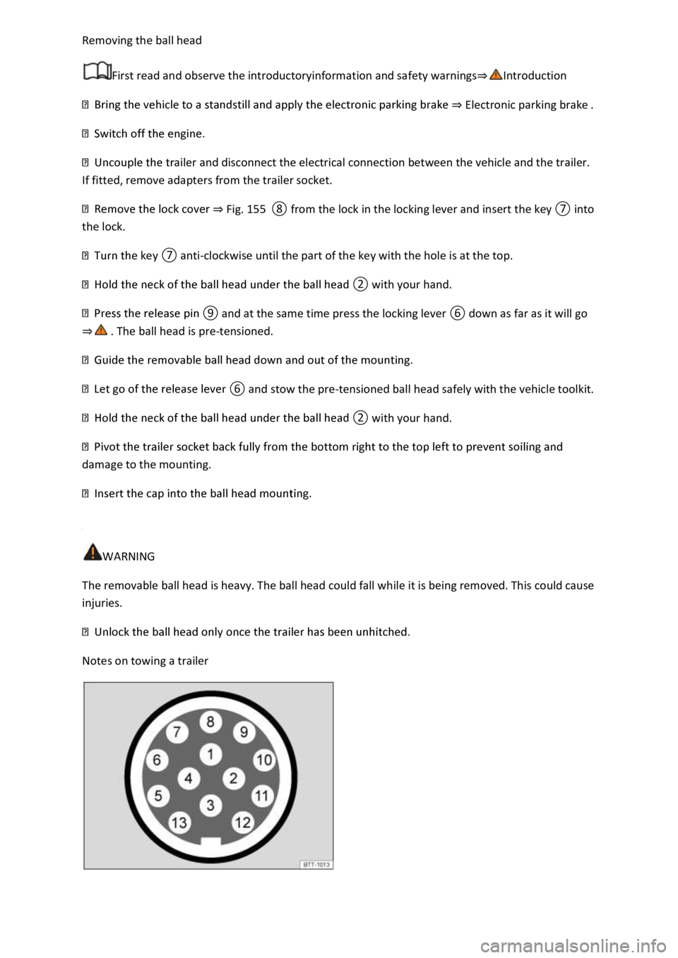
Notes on towing a trailer