2021 TOYOTA PROACE EV Electric
[x] Cancel search: ElectricPage 230 of 360

230
NOTIC E
Tyre inflation pressures are indicated on this label.For more information on Identification markings, particularly this label, refer to the corresponding section.
Composition of the kit
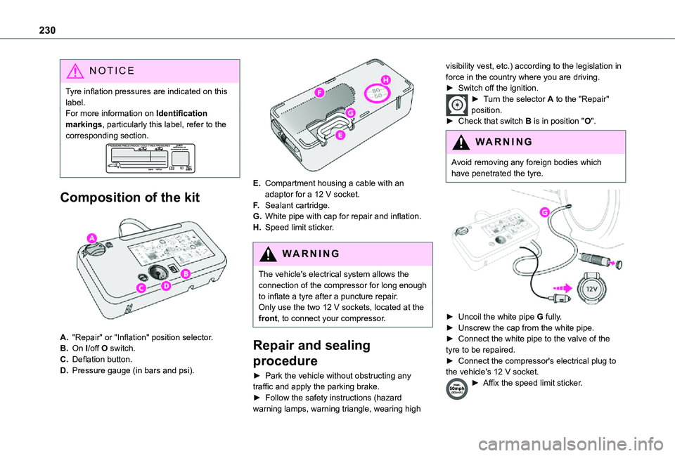
A."Repair" or "Inflation" position selector.
B.On I/off O switch.
C.Deflation button.
D.Pressure gauge (in bars and psi).
E.Compartment housing a cable with an adaptor for a 12 V socket.
F.Sealant cartridge.
G.White pipe with cap for repair and inflation.
H.Speed limit sticker.
WARNI NG
The vehicle's electrical system allows the connection of the compressor for long enough to inflate a tyre after a puncture repair.Only use the two 12 V sockets, located at the front, to connect your compressor.
Repair and sealing
procedure
► Park the vehicle without obstructing any
traffic and apply the parking brake.► Follow the safety instructions (hazard warning lamps, warning triangle, wearing high
visibility vest, etc.) according to the legislation in force in the country where you are driving.► Switch off the ignition.► Turn the selector A to the "Repair" position.► Check that switch B is in position "O".
WARNI NG
Avoid removing any foreign bodies which
have penetrated the tyre.
► Uncoil the white pipe G fully.► Unscrew the cap from the white pipe.► Connect the white pipe to the valve of the tyre to be repaired.► Connect the compressor's electrical plug to the vehicle's 12 V socket.
► Affix the speed limit sticker.
Page 231 of 360

231
In the event of a breakdown
8
WARNI NG
The speed limit sticker must be secured to the interior of the vehicle in the driver's field of vision, to remind you that a wheel is in temporary use.
► Start the vehicle and leave the engine running.
NOTIC E
Do not start the compressor before connecting the white pipe to the tyre valve: the sealant product would be expelled through the pipe.
► Switch on the compressor by moving switch B to position I until the tyre pressure reaches 2.0 bars. The sealant product is injected under pressure into the tyre; do not disconnect the pipe from the valve during this operation (risk of blowback).
NOTIC E
If after approximately seven minutes this pressure is not reached, this indicates that the tyre is not repairable; contact any authorized Toyota retailer or Toyota authorized repairer,
or any reliable repairer for assistance.
► Remove the kit and screw the cap back on the white pipe. Take care to avoid contaminating
the vehicle with traces of fluid. Keep the kit to hand.
WARNI NG
Take care, the sealant product is harmful if swallowed and causes irritation to the eyes.Keep this product out of the reach of children.The use-by date of the fluid is marked on the bottle.
After use, do not discard the bottle in standard waste, take it to any authorized Toyota retailer or Toyota authorized repairer, or any reliable repairer waste disposal site.Do not forget to obtain a new bottle of sealant, available from any authorized Toyota retailer or Toyota authorized repairer, or any reliable repairer.
► Drive immediately for approximately three miles (five kilometres), at reduced speed
(between 12 and 37 mph (20 and 60 km/h)), to plug the puncture.
► Stop to check the repair and measure the tyre pressure using the kit.
Inflating, adjusting and
checking tyre pressures
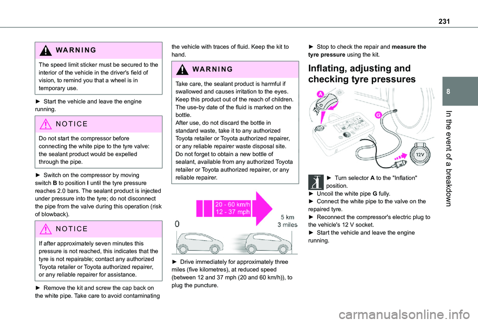
► Turn selector A to the "Inflation" position.► Uncoil the white pipe G fully.► Connect the white pipe to the valve on the repaired tyre.► Reconnect the compressor's electric plug to
the vehicle's 12 V socket.► Start the vehicle and leave the engine running.
Page 234 of 360

234
Access to the spare wheel
► Access to the spare wheel is from the rear.► Depending on version, open the side-hinged doors or the tailgate.
NOTIC E
To avoid any unwanted opening of the electric side door(s), deactivate the Hands-Free Access function in the vehicle configuration
menu.For more information on the Hands-Free Sliding Side Door, refer to the corresponding section.
► If the vehicle is fitted with a towing device, raise the rear of the vehicle using the jack (must be at jacking point B) to allow sufficient space to remove the spare wheel.
Removing the spare wheel from the
carrier
► Access the carrier bolt, located on the rear door sill.► Slacken the bolt using the wheelbrace (about 14 turns) until the carrier is low enough to allow the carrier hook to be disengaged.
► Release the carrier from the hook and place the spare wheel next to the wheel to be changed.
Putting the spare wheel back in the
carrier
► Position the wheel facing the carrier.► Progressively return the wheel to the carrier by pushing alternately at left and right until it is clear of the hook fixing area.► Engage the carrier on the hook, then tighten the bolt using the wheelbrace handle until the bolt is tight.Tyre in the carrierYou can change the size of the tyre on the spare wheel by following the instructions below.
Page 235 of 360

235
In the event of a breakdown
8
Original tyre sizeCompact-MediumLong
215/65 R16Placing a 225 wheel in the carrier is prohibited.
There is no restriction.215/60 R17
215/60 R17 M&S
225/55 R17Placing a 215 wheel in the carrier is not recommended (risk of noise).
NOTIC E
A punctured tyre of size 215 or 225 can be placed in the carrier.
Removing a wheel
WARNI NG
Parking the vehicleImmobilise the vehicle where it does not obstruct traffic: the ground must be level, stable and non-slippery.With a manual gearbox, engage first gear then switch off the ignition to block the wheels.With an automatic gearbox, place the gear selector in position P then switch off the ignition to block the wheels. With a drive selector, place the gear selector in position P then switch off the ignition to block the wheels.Apply the parking brake, unless it is programmed to automatic mode (for an electric parking brake), and check that the indicator lamp lights up on the instrument panel.Ensure that the occupants have left the
vehicle and are located in a safe place.Never go underneath a vehicle raised using a jack; use an axle stand.With an electric parking brake, place a chock against the wheel diagonally opposite to the one being replaced.
► With a steel wheel, remove the bolt cover using tool 3 or the wheel trim by hand.► With an alloy wheel, remove the cover from each of the bolts using tool 3.► If the vehicle is so equipped, fit security bolt socket 4 to wheelbrace 1 to slacken the security bolt.► Slacken (without removing) the other wheel bolts using just wheelbrace 1.
► Place the foot of the jack on the ground and ensure that it is directly below the A or B jacking point provided on the underbody, whichever is
closest to the wheel to be changed.
Page 241 of 360

241
In the event of a breakdown
8
Rear lamps
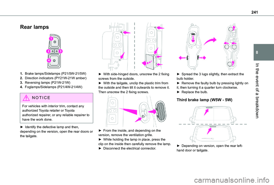
1.Brake lamps/Sidelamps (P21/5W-21/5W)
2.Direction indicators (PY21W-21W amber)
3.Reversing lamps (P21W-21W)
4.Foglamps/Sidelamps (P21/4W-21/4W)
NOTIC E
For vehicles with interior trim, contact any authorized Toyota retailer or Toyota authorized repairer, or any reliable repairer to have the work done.
► Identify the defective lamp and then, depending on the version, open the rear doors or the tailgate.
► With side-hinged doors, unscrew the 2 fixing screws from the outside.► With the tailgate, unclip the plastic trim from the outside and then tilt it outwards to remove it. Then unscrew the 2 fixing screws.
► From the inside, and depending on the version, remove the ventilation grille.► While holding the lamp in place, press the clip on the inside then carefully remove the lamp.► Disconnect the electrical connector.
► Spread the 3 lugs slightly, then extract the bulb holder.► Remove the faulty bulb by pressing lightly on it, then turning it a quarter turn clockwise.► Replace the bulb.
Third brake lamp (W5W - 5W)
► Depending on version, open the rear left-hand door or tailgate.
Page 242 of 360

242
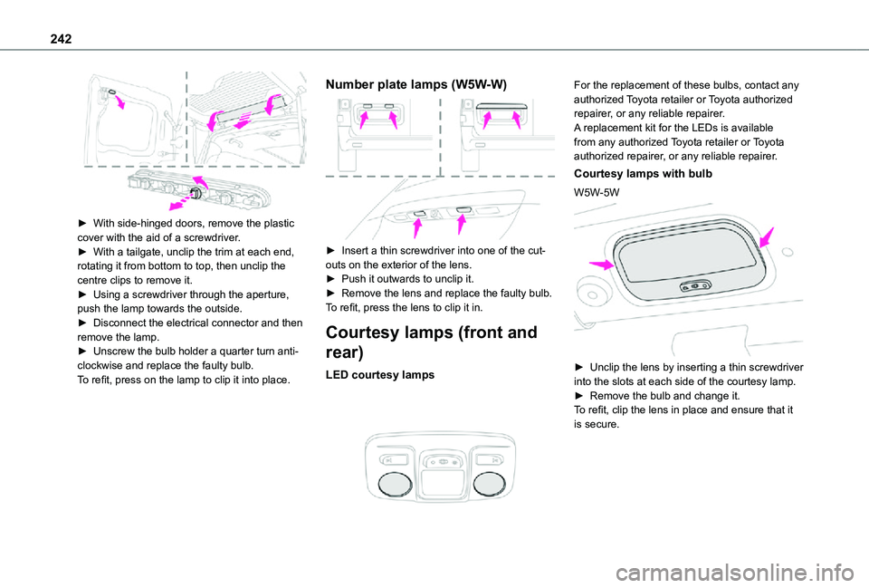
► With side-hinged doors, remove the plastic cover with the aid of a screwdriver.► With a tailgate, unclip the trim at each end, rotating it from bottom to top, then unclip the centre clips to remove it.► Using a screwdriver through the aperture, push the lamp towards the outside.► Disconnect the electrical connector and then remove the lamp.► Unscrew the bulb holder a quarter turn anti-clockwise and replace the faulty bulb.To refit, press on the lamp to clip it into place.
Number plate lamps (W5W-W)
► Insert a thin screwdriver into one of the cut-outs on the exterior of the lens.► Push it outwards to unclip it.► Remove the lens and replace the faulty bulb.To refit, press the lens to clip it in.
Courtesy lamps (front and
rear)
LED courtesy lamps
For the replacement of these bulbs, contact any authorized Toyota retailer or Toyota authorized repairer, or any reliable repairer.A replacement kit for the LEDs is available from any authorized Toyota retailer or Toyota authorized repairer, or any reliable repairer.
Courtesy lamps with bulb
W5W-5W
► Unclip the lens by inserting a thin screwdriver into the slots at each side of the courtesy lamp.► Remove the bulb and change it.
To refit, clip the lens in place and ensure that it is secure.
Page 243 of 360

243
In the event of a breakdown
8
Platform cab (rear lamps)
1.Direction indicators (P21W-21W).
2.Brake lamps (P21W-21W).
3.Sidelamps (R10W-10W).
4.Reversing lamps (P21W-21W).
5.Foglamps (P21W-21W).
► Locate the faulty bulb.► Unscrew the 4 fixing screws from the lens unit and remove it.► Remove the faulty bulb by pressing lightly on it, then turning it a quarter turn clockwise.► Change the bulb.
Changing a fuse
Access to tools and to the
dashboard fusebox
The extraction tweezers and the fuses are located behind the fusebox cover.► Unclip the cover by pulling at the top left, then right.► Remove the cover completely.
Changing a fuse
Before changing a fuse:► Identify the cause of the fault and fix it.► Switch off all power consumption.► Immobilise the vehicle and switch off the ignition.► Identify the defective fuse using the current allocation tables and diagrams.To replace a fuse, it is essential to:► Use the special tweezers to extract the fuse from its housing and check the condition of its filament.► Always replace the failed fuse with a fuse of the same rating (same colour); use of a different rating may cause malfunctions - risk of fire!If the fault recurs soon after replacing a fuse, have the electrical system checked by any authorized Toyota retailer or Toyota authorized repairer, or any reliable repairer.
NOTIC E
Complete fuse allocation tables and corresponding diagramsFor more information, contact a any authorized Toyota retailer or Toyota authorized repairer, or any reliable repairer.
Page 244 of 360

244
WARNI NG
The replacement of a fuse not shown in the allocation tables could cause a serious malfunction of the vehicle.Consult any authorized Toyota retailer or Toyota authorized repairer, or any reliable repairer.
GoodFaulty
Tweezers
NOTIC E
Installing electrical accessoriesThe vehicle's electrical system is designed to
operate with standard or optional equipment.Before fitting other electrical equipment or accessories to your vehicle, contact any authorized Toyota retailer or Toyota
authorized repairer, or any reliable repairer.
WARNI NG
TOYOTA accepts no responsibility for the cost incurred in repairing the vehicle or for rectifying malfunctions resulting from the installation of accessories not supplied or not recommended by TOYOTA and not installed in accordance with its recommendations, in particular when the combined power consumption of all of the additional equipment connected exceeds 10 milliamperes.
NOTIC E
For more information on installing a towbar or TAXI type equipment, contact any authorized Toyota retailer or Toyota authorized repairer, or any reliable repairer.
Version 1 (Eco)
The fuses described below vary according to the equipment in your vehicle.
Fuse N°Rating(Amps)Functions
F415Horn.
F520Front/rear screenwash pump.
F620Front/rear screenwash pump.
F710Rear 12 V accessory socket.
F820Single or double rear wipers.
F10/F1130Internal/external locks, front and rear.
F145Alarm, emergency and assistance calls.
F245Touch screen, reversing camera and parking sensors.