Page 25 of 139
26
76G-74E
BEFORE DRIVING3-13
76G-03-03176G-03-032
To reduce the risk of sliding under the belt
during a collision, position the lap portion
of the belt across your lap as low on your
hips as possible and adjust the belt to a
snug fit using the proper method for each
type of the belt as described below. Make
sure that the belt is not twisted.
76G-03-033
To fasten the seat belt, sit up straight and
well back in the seat, pull the buckle tongue
attached to the seat belt across your body
and slide it into the buckle catch on the
opposite side until you hear a “click”.
76G-03-030
Page 26 of 139
2776G-74E
BEFORE DRIVING
3-14
ww ww
w WARNING
To Adjust the Belt
Pull the shoulder portion of the belt
upwards through the tongue plate.
The length of the diagonal shoulder strap
adjusts itself to allow freedom of movement.
The seat belt has an emergency locking
retractor (ELR), which is designed to lock
the seat belt only during a sudden stop or
impact.
No modifications or additions of any
sort should be made to the seat belt
or its operating mechanism.
76G-03-035
Seat Belt Inspection
Periodically inspect the seat belts to make
sure they work properly and are not
damaged. Check the webbing, buckles, latch
plates, retractors, anchorages and guide
loops. Replace any seat belts which do not
work properly or are damaged.
76G-03-036
To unfasten the belt, press the release
button on the buckle catch.
76G-03-034
Page 27 of 139
28
76G-74E
BEFORE DRIVING3-15
To lengthen, release the tounge from the
buckle unit, pull the tounge (adjuster) in
the direction of the arrow, at right angles
to the belt. The tounge should then be
refitted into the buckle unit and the belt
tightened as previously described.
76G-03-038
NOTE:To identify the center seat belt buckle catchand tongue in the rear seat, "CENTER" is
moulded on the buckle catch and tongue ofthe center lap belt. The buckle catches aredesigned so a buckle tongue can not be
inserted into the wrong buckle catch.
76G-03-039
On this belt the adjuster is incorporated in
the tounge unit.
To tighten the belt, pull the free end of
the belt across alongside the lap strap
until it is adjusted to a snug comfortable
position.LAP BELT (if equipped)
76G-03-037
Page 28 of 139
2976G-74E
4
STEERING COLUMN CONTROLS
Ignition Switch........................................................................\
............................ 4-1
Lighting/Turn Signal Control Lever ................................................................ 4-2
Hazard Warning Switch ........................................................................\
............ 4-5
Windscreen Wiper and Washer Lever .......................................................... 4-5
Horn ........................................................................\
............................................... 4-6
Electrical Power Steering (if equipped) ........................................................ 4-7
Page 29 of 139
30
76G-74E
IGNITION SWITCHThe ignition switch has the following four
positions: Do not use any locally made key.
Should you require duplicate key, place your order with MARUTI
SUZUKI dealer only. LOCK
This is the normal parking position. It is the
only position in which the key can be
removed.
The “LOCK” position locks the ignition, and
prevents normal use of the steering wheel
after the key is removed.
To release the steering lock, fully insert the
key and turn it clockwise to one of the other
positions. If you have trouble turning the
key to unlock the steering, try turning the
steering wheel slightly to the right or left
while turning the key.
To avoid possible injury, do not operate
controls by reaching through the steering
wheel.
STEERING COLUMN CONTROLS
ww ww
w WARNING
ww
ww
w WARNING
4-1
76G-04-001 76G-04-003
76G-04-002
Page 30 of 139

3176G-74E
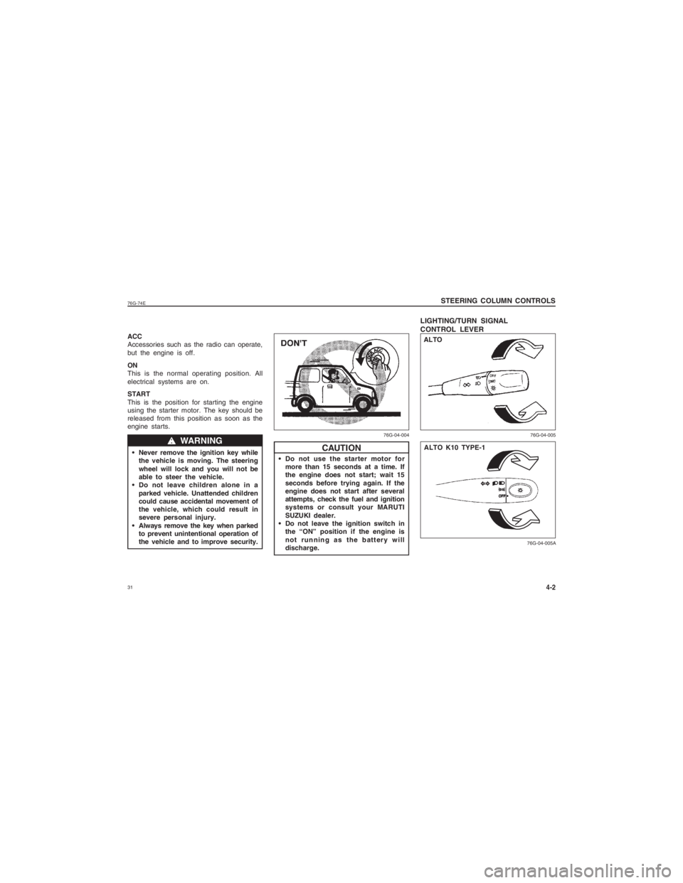
Do not use the starter motor formore than 15 seconds at a time. If
the engine does not start; wait 15
seconds before trying again. If the
engine does not start after several
attempts, check the fuel and ignition
systems or consult your MARUTI
SUZUKI dealer.
Do not leave the ignition switch in the “ON” position if the engine is
not running as the battery will
discharge.
LIGHTING/TURN SIGNAL
CONTROL LEVER STEERING COLUMN CONTROLS
ACC
Accessories such as the radio can operate,
but the engine is off.
ON
This is the normal operating position. All
electrical systems are on.
START
This is the position for starting the engine
using the starter motor. The key should be
released from this position as soon as the
engine starts.
Never remove the ignition key while the vehicle is moving. The steering
wheel will lock and you will not be
able to steer the vehicle.
Do not leave children alone in a
parked vehicle. Unattended children
could cause accidental movement of
the vehicle, which could result in
severe personal injury.
Always remove the key when parked to prevent unintentional operation of
the vehicle and to improve security.
ww ww
w WARNING
CAUTION
4-2
76G-04-005
76G-04-004
ALTO
76G-04-005A
ALTO K10 TYPE-1
Page 31 of 139
32
76G-74E
STEERING COLUMN CONTROLS4-3
76G-04-005B
With the headlights on, push the lever
forward to switch to the high beams (main
beams) or pull the lever toward you to
switch to the low beams. When the high
beams (main beams) are on, a light on the
instrument panel will come on. To flash the
high beams (main beams) pull the lever
slightly towards you and release it.
76G-04-006
ALTO K10 TYPE-2
76G-04-006A
76G-04-006B
ALTO K10 TYPE-1ALTO K10 TYPE-2
ALTO
This control lever is located on the outboard
side of the steering column. Operate the
lever as described below.
Lighting Operation
To turn the lights on or off, twist the knob
on the end of the lever. There are three
positions: in the “OFF” position all lights are
off; in the middle position the front parking
lights, tail-lights, registration plate light, and
instrument lights are on, but the headlights
are off; in the third position the headlights
come on in addition to the other lights.
Page 32 of 139
3376G-74E
STEERING COLUMN CONTROLS
Turn Signal Operation
With the ignition switch in the “ON” position,
move the lever up or down to activate the
left or right turn signals.
Normal Turn Signal
Move the lever clockwise until it clicks to
signal a right turn or anticlockwise to signal
a left turn. When the turn is completed, the
signal will cancel and the lever will return
to its normal position.
4-4
76G-04-008
76G-04-007
76G-04-007A
76G-04-007B
ALTO K10 TYPE-1 ALTO K10 TYPE-2
ALTO ALTO
76G-04-008A
ALTO K10 TYPE-1