2021 Peugeot 308 boot
[x] Cancel search: bootPage 56 of 244
54
Lighting and visibility
Three flashes
► Press briefly upwards or downwards, without
going beyond the point of resistance; the
direction indicators will flash 3 times.
Headlamp beam height
adjustment
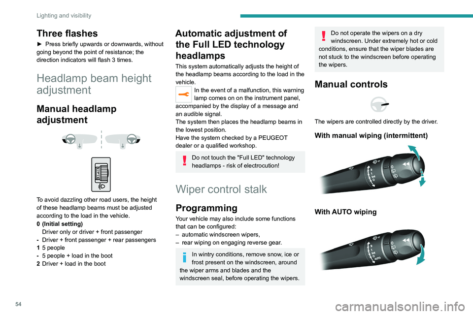
Manual headlamp
adjustment
To avoid dazzling other road users, the height
of these headlamp beams must be adjusted
according to the load in the vehicle.
0 (Initial setting) Driver only or driver + front passenger
- Driver + front passenger + rear passengers
1 5 people
- 5 people + load in the boot
2 Driver + load in the boot
Automatic adjustment of
the Full LED technology
headlamps
This system automatically adjusts the height of
the headlamp beams according to the load in the
vehicle.
In the event of a malfunction, this warning
lamp comes on on the instrument panel,
accompanied by the display of a message and
an audible signal.
The system then places the headlamp beams in
the lowest position.
Have the system checked by a PEUGEOT
dealer or a qualified workshop.
Do not touch the "Full LED" technology
headlamps - risk of electrocution!
Wiper control stalk
Programming
Your vehicle may also include some functions
that can be configured:
–
automatic windscreen wipers,
–
rear wiping on engaging reverse gear
.
In wintry conditions, remove snow, ice or
frost present on the windscreen, around
the wiper arms and blades and the
windscreen seal, before operating the wipers.
Do not operate the wipers on a dry
windscreen. Under extremely hot or cold
conditions, ensure that the wiper blades are
not stuck to the windscreen before operating
the wipers.
Manual controls
The wipers are controlled directly by the driver.
With manual wiping (intermittent)
With AUTO wiping
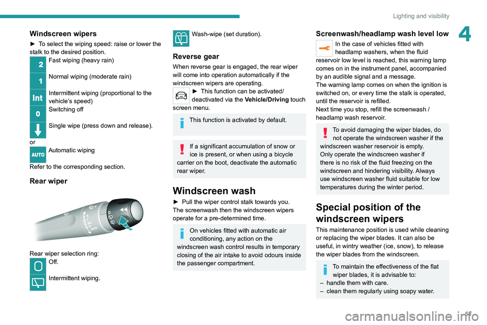
Windscreen wipers
► To select the wiping speed: raise or lower the
stalk to the desired position.
Fast wiping (heavy rain)
Normal wiping (moderate rain)
Intermittent wiping (proportional to the
vehicle’s speed)
Switching off
Single wipe (press down and release).
or
Automatic wiping
Refer to the corresponding section.
Rear wiper
Rear wiper selection ring:Off.
Intermittent wiping.
Page 57 of 244
55
Lighting and visibility
4Windscreen wipers
► To select the wiping speed: raise or lower the
stalk to the desired position.
Fast wiping (heavy rain)
Normal wiping (moderate rain)
Intermittent wiping (proportional to the
vehicle’s speed)
Switching off
Single wipe (press down and release).
or
Automatic wiping
Refer to the corresponding section.
Rear wiper
Rear wiper selection ring:Off.
Intermittent wiping.
Wash-wipe (set duration).
Reverse gear
When reverse gear is engaged, the rear wiper
will come into operation automatically if the
windscreen wipers are operating.
► This function can be activated/
deactivated via the V
ehicle/Driving touch
screen menu.
This function is activated by default.
If a significant accumulation of snow or
ice is present, or when using a bicycle
carrier on the boot, deactivate the automatic
rear wiper.
Windscreen wash
► Pull the wiper control stalk towards you.
The screenwash then the windscreen wipers
operate for a pre-determined time.
On vehicles fitted with automatic air
conditioning, any action on the
windscreen wash control results in temporary
closing of the air intake to avoid odours inside
the passenger compartment.
Screenwash/headlamp wash level low
In the case of vehicles fitted with
headlamp washers, when the fluid
reservoir low level is reached, this warning lamp
comes on in the instrument panel, accompanied
by an audible signal and a message.
The warning lamp comes on when the ignition is
switched on, or every time the stalk is operated,
until the reservoir is refilled.
Next time you stop, refill the screenwash /
headlamp wash reservoir.
To avoid damaging the wiper blades, do not operate the windscreen washer if the
windscreen washer reservoir is empty.
Only operate the windscreen washer if
there is no risk of the fluid freezing on the
windscreen and hindering visibility. Always
use windscreen washer fluid suitable for low
temperatures during the winter period.
Special position of the
windscreen wipers
This maintenance position is used while cleaning
or replacing the wiper blades. It can also be
useful, in wintry weather (ice, snow), to release
the wiper blades from the windscreen.
To maintain the effectiveness of the flat wiper blades, it is advisable to:
–
handle them with care.
–
clean them regularly using soapy water
.
Page 76 of 244
74
Safety
“ISOFIX" mountings
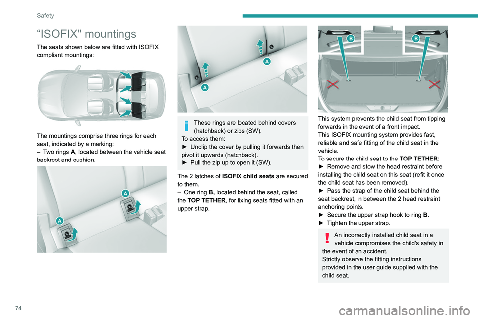
The seats shown below are fitted with ISOFIX
compliant mountings:
The mountings comprise three rings for each
seat, indicated by a marking:
–
T
wo rings A, located between the vehicle seat
backrest and cushion.
These rings are located behind covers (hatchback) or zips (SW).
To access them:
►
Unclip the cover by pulling it forwards then
pivot it upwards (hatchback).
►
Pull the zip up to open it (SW).
The 2
latches of ISOFIX child seats are secured
to them.
–
One ring
B, located behind the seat, called
the TOP TETHER, for fixing seats fitted with an
upper strap.
This system prevents the child seat from tipping
forwards in the event of a front impact.
This ISOFIX mounting system provides fast,
reliable and safe fitting of the child seat in the
vehicle.
To secure the child seat to the TOP TETHER:
►
Remove and stow the head restraint before
installing the child seat on this seat (refit it once
the child seat has been removed).
►
Pass the strap of the child seat behind the
seat backrest, in between the 2 head restraint
anchoring points.
►
Secure the upper strap hook to ring
B
.
►
T
ighten the upper strap.
An incorrectly installed child seat in a vehicle compromises the child's safety in
the event of an accident.
Strictly observe the fitting instructions
provided in the user guide supplied with the
child seat.
For information about the options for
fitting ISOFIX child seats in your vehicle,
refer to the summary table.
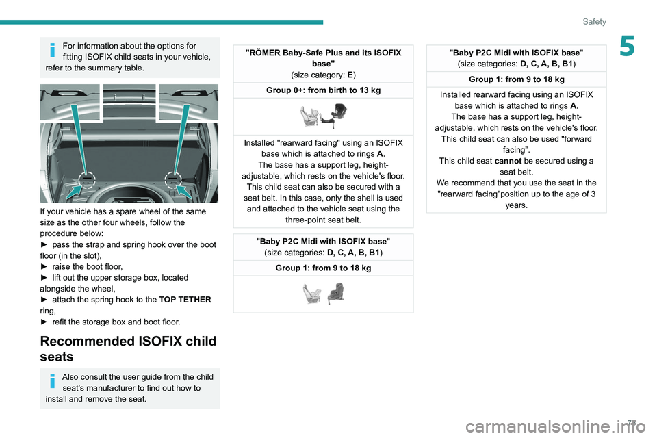
If your vehicle has a spare wheel of the same
size as the other four wheels, follow the
procedure below:
► pass the strap and spring hook over the boot
floor (in the slot),
► raise the boot floor,
► lift out the upper storage box, located
alongside the wheel,
► attach the spring hook to the TOP TETHER
ring,
► refit the storage box and boot floor.
Recommended ISOFIX child
seats
Also consult the user guide from the child
seat’s manufacturer to find out how to
install and remove the seat.
Page 77 of 244
75
Safety
5For information about the options for
fitting ISOFIX child seats in your vehicle,
refer to the summary table.
If your vehicle has a spare wheel of the same
size as the other four wheels, follow the
procedure below:
►
pass the strap and spring hook over the boot
floor (in the slot),
►
raise the boot floor
,
►
lift out the upper storage box, located
alongside the wheel,
►
attach the spring hook to the
TOP TETHER
ring,
►
refit the storage box and boot floor
.
Recommended ISOFIX child
seats
Also consult the user guide from the child seat’s manufacturer to find out how to
install and remove the seat.
"RÖMER Baby-Safe Plus and its ISOFIX base"
(size category: E)
Group 0+: from birth to 13 kg
Installed "rearward facing" using an ISOFIX base which is attached to rings A .
The base has a support leg, height-
adjustable, which rests on the vehicle's floor. This child seat can also be secured with a
seat belt. In this case, only the shell is used and attached to the vehicle seat using the three-point seat belt.
"Baby P2C Midi with ISOFIX base "
(size categories: D, C, A, B, B1)
Group 1: from 9 to 18 kg
"Baby P2C Midi with ISOFIX base "
(size categories: D, C, A, B, B1)
Group 1: from 9 to 18 kg
Installed rearward facing using an ISOFIX base which is attached to rings A.
The base has a support leg, height-
adjustable, which rests on the vehicle's floor. This child seat can also be used "forward facing”.
This child seat cannot be secured using a seat belt.
We recommend that you use the seat in the "rearward facing"position up to the age of 3 years.
Page 123 of 244
121
Driving
6Parking sensors
Refer to the General recommendations on the
use of driving and manoeuvring aids.
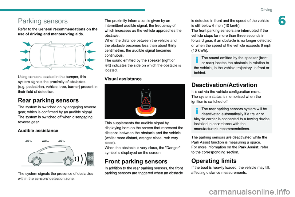
Using sensors located in the bumper, this
system signals the proximity of obstacles
(e.g.
pedestrian, vehicle, tree, barrier) present in
their field of detection.
Rear parking sensors
The system is switched on by engaging reverse
gear, which is confirmed by an audible signal.
The system is switched off when disengaging
reverse gear.
Audible assistance
The system signals the presence of obstacles
within the sensors’ detection zone. The proximity information is given by an
intermittent audible signal, the frequency of
which increases as the vehicle approaches the
obstacle.
When the distance between the vehicle and
the obstacle becomes less than about thirty
centimetres, the audible signal becomes
continuous.
The sound emitted by the speaker (right or
left) indicates the side on which the obstacle is
located.
Visual assistance
This supplements the audible signal by
displaying bars on the screen that represent the
distance between the obstacle and the vehicle
(white: more distant, orange: close, red: very
close).
When the obstacle is very close, the "Danger"
symbol is displayed on the screen.
Front parking sensors
In addition to the rear parking sensors, the front
parking sensors are triggered when an obstacle
is detected in front and the speed of the vehicle
is still below 6 mph (10
km/h).
The front parking sensors are interrupted if the
vehicle stops for more than three seconds in
forward gear, if an obstacle is no longer detected
or when the speed of the vehicle exceeds 6
mph
(10
km/h).
The sound emitted by the speaker (front or rear) locates the obstacle in relation to
the vehicle, in the vehicle trajectory, in front or
behind.
Deactivation/Activation
It is set via the vehicle configuration menu.
The system status is memorised when the
ignition is switched off.
The rear parking sensors system will be deactivated automatically if a trailer or
bicycle carrier is connected to a towing device
installed in accordance with the
manufacturer's recommendations.
The parking sensors are deactivated while the
Park Assist function is measuring a space.
For more information on the Park Assist, refer
to the corresponding section.
Operating limits
If the boot is heavily loaded, the vehicle may tilt,
affecting distance measurements.
Page 139 of 244
137
Practical information
7► Insert the key into the lock 7.
► Open the lock using the key .
► Hold the towball 5 firmly in one hand; using
the other hand, pull and turn the wheel 6 fully in
a clockwise direction until it stops; do not release
the wheel.
► Extract the towball from the base of its
carrier 1.
►
Release the wheel; it automatically locks in
the unlocked position (position B
).
► Replace the protective plug 2 into the
carrier 1.
►
Stow the towball in its bag to protect it from
knocks and dirt.
Maintenance
Correct operation is only possible if the towball
and its carrier are kept clean.
Before cleaning the vehicle with a high-pressure
jet wash, the towball must be removed and the
protective plug fitted to the carrier.
Apply the label provided to a clearly visible area, close to the carrier or in the
boot.
Go to a PEUGEOT dealer or a qualified
workshop for any work on the towbar system.
Towbar with quickly detachable towball (SW)
Presentation
No tools are required to install or remove this
genuine towing device.
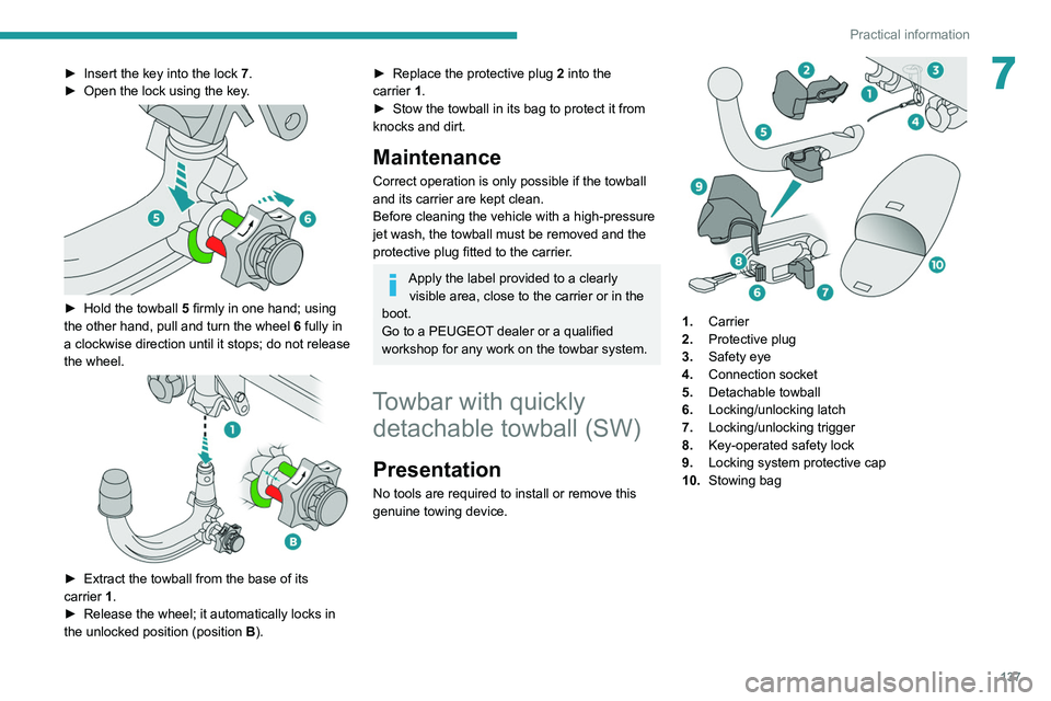
1. Carrier
2. Protective plug
3. Safety eye
4. Connection socket
5. Detachable towball
6. Locking/unlocking latch
7. Locking/unlocking trigger
8. Key-operated safety lock
9. Locking system protective cap
10. Stowing bag
Page 152 of 244
150
In the event of a breakdown
Tool kit
This is a set of tools provided with the vehicle.
Its content depends on your vehicle's equipment:
–
temporary puncture repair kit,
–
spare wheel.
Accessing the tools
The tools are stored in the boot under the floor.
All of these tools are specific to your vehicle and may vary depending on
equipment.
Do not use them for any other purposes.
The jack must only be used to change a wheel with a damaged or punctured tyre.
Do not use any jack other than the one
supplied with this vehicle.
If the vehicle does not have its original jack,
contact a PEUGEOT dealer or a qualified
workshop to obtain the correct jack for it.
The jack meets European standards, as
defined in the Machinery Directive 2006/42/
CE.
The jack does not require any maintenance.
List of tools
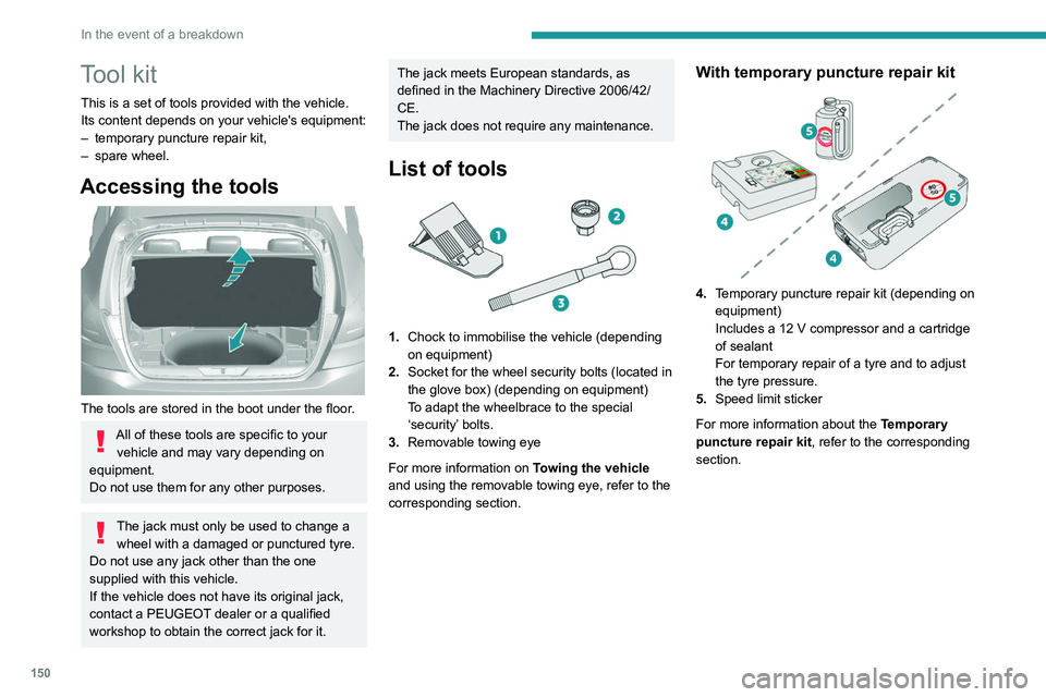
1. Chock to immobilise the vehicle (depending
on equipment)
2. Socket for the wheel security bolts (located in
the glove box) (depending on equipment)
To adapt the wheelbrace to the special
‘security’ bolts.
3. Removable towing eye
For more information on Towing the vehicle
and using the removable towing eye, refer to the
corresponding section.
With temporary puncture repair kit
4. Temporary puncture repair kit (depending on
equipment)
Includes a 12 V compressor and a cartridge
of sealant
For temporary repair of a tyre and to adjust
the tyre pressure.
5. Speed limit sticker
For more information about the Temporary
puncture repair kit, refer to the corresponding
section.
With spare wheel
5. Wheelbrace
For removing the wheel trim and the wheel
bolts.
6. Jack with integrated handle
To raise the vehicle.
7. Wheel bolt cap removal tool (depending on
equipment)
For removing the wheel bolt head finishers on
alloy wheels.
For more information on the Spare wheel, refer
to the corresponding section.
Page 159 of 244
157
In the event of a breakdown
8Tyre inflation pressures are indicated on this label.
► Adjust the pressure using the compressor
(to inflate: set switch B to position "I"; to deflate:
set switch B to position "O" and press button C),
following the vehicle's tyre pressure label.
If, after approximately seven minutes,
this pressure is not reached, this
indicates that the tyre is irreparable; contact a
PEUGEOT dealer or a qualified workshop for
assistance.
►
Remove the kit and stow it.
Do not drive more than 125 miles
(200 km) with a repaired tyre; see a
PEUGEOT dealer or a qualified workshop to
have the tyre changed.
Should the pressure of one or more tyres
be adjusted, it is necessary to reinitialise
the under-inflation detection system.
For more information on Tyre under-inflation
detection, refer to the corresponding section.
Spare wheel
Scan the QR Code on page 3 to view
explanatory videos.
For more information on the Tool kit,
refer to the corresponding section.
The jack must only be used to change a wheel with a damaged or punctured tyre.
The jack does not require any maintenance.
The jack meets European standards, as
defined in the Machinery Directive 2006/42/
EC.
Some parts of the jack such as the
screws and hinges could cause injury:
avoid touching them.
Carefully remove any traces of grease.
Wheel with wheel trim
When refitting the wheel, refit the wheel
trim, starting by aligning the cutout with the
valve and then pushing the trim into place all
round its edge with the palm of your hand.
►
Park the vehicle without obstructing any
traffic and apply the parking brake.
►
Follow the safety instructions (hazard
warning lamps, warning triangle, wearing high
visibility vest, etc.) according to the legislation in
force in the country where you are driving. ►
Switch off the ignition.
Accessing the spare wheel
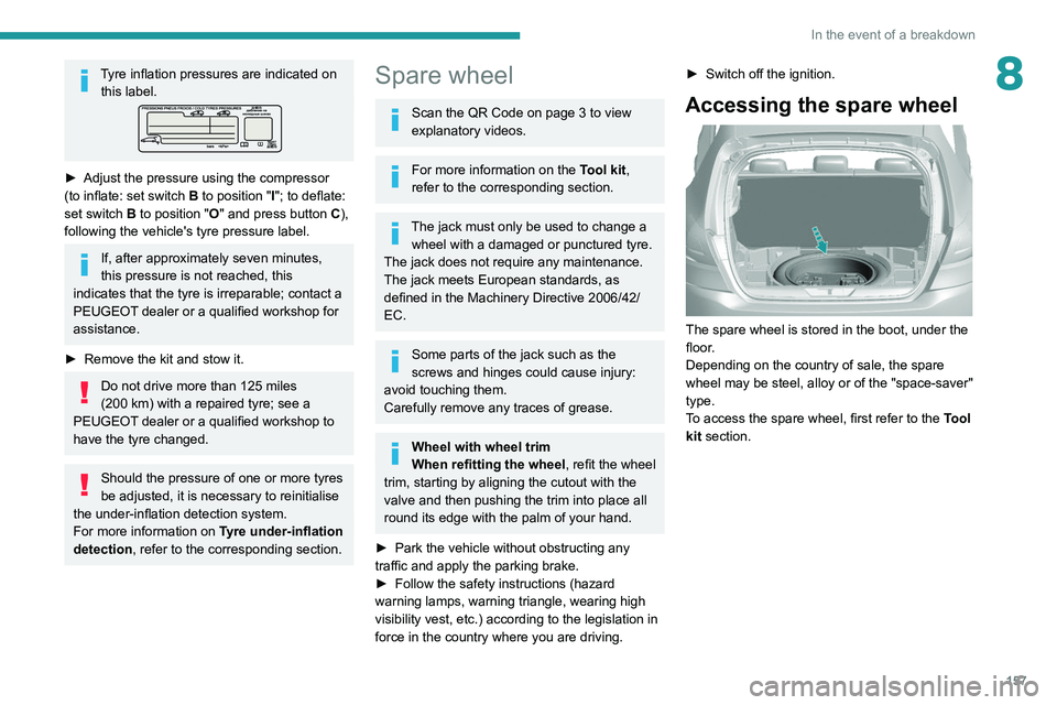
The spare wheel is stored in the boot, under the
floor.
Depending on the country of sale, the spare
wheel may be steel, alloy or of the "space-saver"
type.
To access the spare wheel, first refer to the Tool
kit section.