2021 NISSAN NV200 light
[x] Cancel search: lightPage 135 of 300
position.
2. Turn the air flow control dial to the
position.
3. Turn the
fan speed control dial to
the desired position.
4. Turn the temperature control dial to the desired position.
Heating and defogging
This mode heats the interior and defogs
the windshield.
1. Move the air intake lever to the
position.
2. Turn the air flow control dial to the
position.
3. Turn the
fan speed control dial to
the desired position.
4. Turn the temperature control dial to the desired position between the middle
and the hot position.
When the
orposition is se-
lected, the air conditioner automatically
turns on (however, the indicator light will
not illuminate). In this position, the air con-
ditioner cannot be turned off. When the air
flow control is turned to any position other than
or(the air conditioner will
continue operating) and can be turned off
using the air conditioner button. This dehu-
midifies the air, which helps defog the
windshield.
Operating tips
Clear snow and ice from the wiper blades
and air inlet in front of the windshield.
This improves heater operation.
AIR CONDITIONER OPERATION
Start the engine, turn thefan speed
control dial to the desired position, and
press the
button to activate the air
conditioner. When the air conditioner is on,
cooling and dehumidif ying functions are
added to the heater operation.
The air conditioner cooling function op-
erates only when the engine is running.
Cooling
This mode is used to cool and dehumidif y
the air.
1. Move the air intake lever to the
position.
2. Turn the air flow control dial to the
position. 3. Turn the
fan speed control dial to
the desired position.
4. Press the
button. The indicator
light comes on.
5. Turn the temperature control dial to the desired position.
• For quick cooling when the outside tem- perature is high, move the air intake lever
to the
position. Be sure to return to
theposition for normal cooling.
Dehumidified heating
This mode is used to heat and dehumidif y
the air.
1. Move the air intake lever to the
position.
2. Turn the air flow control dial to the
position.
3. Turn the
fan speed control dial to
the desired position.
4. Press the
button. The indicator
light comes on.
5. Turn the temperature control dial to the desired position.
Monitor, climate, audio, phone and voice recognition systems4-13
Page 136 of 300
position.
2. Turn the air flow control dial to the
position.
3. Turn the
fan speed control dial to
the desired position. When theorposition is selected, the air condi-
tioner automatically turns on (however,
the indicator light will not illuminate). In
this position, the air conditioner cannot
be turned off. When the air flow control is
turned to any position other than
or(the air conditioner will continue
operating). and can be turned off using
the air conditioner button. This dehu-
midifies the air, which helps defog the
windshield.
4. Turn the temperature control dial to the desired position.
Operating tips
€ Keep the windows closed while the airconditioner is in operation.
€ Af ter parking in the sun, drive for 2 or 3 minutes with the windows open to vent
hot air from the passenger compart-
ment before closing the windows. This
allows the air conditioner to cool the inte-
rior more quickly.
€ The air conditioning system should be
operated for approximately 10 minutes
at least once a month. This helps pre-
vent damage to the system due to lack
of lubrication.
• A visible mist may be seen coming from the ventilators in hot, humid conditions
as the air is cooled rapidly. This does not
indicate a malfunction.
• If the high temperature warning light
illuminates in red indicating en-
gine coolant temperature is over the
normal range, turn the air conditioner
off. For additional information, see “If
your vehicle overheats” (P. 6-12).
AIR FLOW CHARTS
The following charts show the button and
dial positions for MAXIMUM AND QUICK
heating, cooling or defrosting. The air in-
take lever should always be in the
position for heating and defrosting.
4-14Monitor, climate, audio, phone and voice recognition systems
Page 141 of 300
CAUTION
• Keep the antenna as far away as pos-
sible from the electronic control
modules.
• Keep the antenna wire more than 8 in
(20 cm) away from the electronic
control system harnesses. Do not
route the antenna wire next to any
harness.
• Adjust the antenna standing-wave
ratio as recommended by the
manufacturer.
• Connect the ground wire from the CB
radio chassis to the body.
• For additional information, it is rec-
ommended that you visit a NISSAN
dealer for this service. “Made for iPod”, “Made for iPhone” and
“Made for iPad” mean that an electronic
accessory has been designed to connect
specifically to iPod, iPhone or iPad, respec-
tively, and has been certified by the devel-
oper to meet Apple performance stan-
dards. Apple is not responsible for the
operation of this device or its compliance
with safety and regulatory standards.
Please note that the use of this accessory
with iPod, iPhone or iPad may affect wire-
less performance.
iPad, iPhone, iPod classic, iPod nano, iPod
shuffle and iPod touch are trademarks of
Apple Inc., registered in the U.S. and other
countries. Lightning is a trademark of
Apple Inc.
iPod®/IPHONE®
Monitor, climate, audio, phone and voice recognition systems4-19
Page 146 of 300
Additional information:
• When using a wheel without the TPMSsuch as the spare tire, the TPMS does not
monitor the tire pressure of the spare tire.
• The TPMS will activate only when the ve- hicle is driven at speeds above 16 mph (25
km/h). Also, this system may not detect a
sudden drop in tire pressure (for example,
a flat tire while driving).
• The low tire pressure warning light does not automatically turn off when the tire
pressure is adjusted for all four tires. Af ter
all your tires are inflated to the recom-
mended pressure, the vehicle must be
driven at speeds above 16 mph (25 km/h)
to activate the TPMS and turn off the low
tire pressure warning light. Use a tire
pressure gauge to check the tire
pressure.
• The CHECK TIRE PRES (pressure) warning message is displayed in the odometer
when the low tire pressure warning light
is illuminated and low tire pressure is de-
tected. The CHECK TIRE PRES warning
message turns off when the low tire pres-
sure warning light turns off. • The low tire pressure warning light re-
mains illuminated until the tires are in-
flated to the recommended COLD tire
pressure. The CHECK TIRE PRES warning
message is displayed each time the igni-
tion switch is placed in the ON position as
long as the low tire pressure warning light
remains illuminated.
• The CHECK TIRE PRES warning message is not displayed if the low tire pressure
warning light illuminates to indicate a
TPMS malfunction.
• Tire pressure rises and falls depending on the heat caused by the vehicle’s opera-
tion and the outside temperature. Do not
reduce the tire pressure af ter driving be-
cause the tire pressure rises af ter driving.
Low outside temperature can lower the
temperature of the air inside the tire
which can cause a lower tire inflation
pressure. This may cause the low tire
pressure warning light to illuminate. If the
warning light illuminates, check the tire
pressure for all four tires.
• The Tire and Loading Information label is located in the driver's door opening.
For additional information, see “Low tire
pressure warning light” (P. 2-12) and “Tire
Pressure Monitoring System (TPMS)” (P. 6-2).
Page 147 of 300
•When using a wheel without the
TPMS such as the spare tire, when a
spare tire is mounted or a wheel is
replaced, tire pressure will not be in-
dicated, the TPMS will not function
and the low tire pressure warning
light will flash for approximately 1
minute. The light will remain on af ter
1 minute. Have your tires replaced
and/or TPMS system reset as soon as
possible. It is recommended that you
visit a NISSAN dealer for this service.
• Replacing tires with those not origi-
nally specified by NISSAN could af-
fect the proper operation of the
TPMS.
• Do not inject any tire liquid or aerosol
tire sealant into the tires, as this may
cause a malfunction of the tire pres-
sure sensors.
CAUTION
Do not place metalized film or any
metal parts (antenna, etc.) on the win-
dows. This may cause poor reception of
the signals from the tire pressure sen-
sors, and the TPMS will not function
properly. Some devices and transmitters may tem-
porarily interfere with the operation of the
TPMS and cause the low tire pressure
warning light to illuminate.
Some examples are:
• Facilities or electric devices using similar
radio frequencies are near the vehicle.
• If a transmitter set to similar frequencies is being used in or near the vehicle.
• If a computer (or similar equipment) or a DC/AC converter is being used in or near
the vehicle.
The low tire pressure warning light may
illuminate in the following cases:
• If the vehicle is equipped with a wheel and tire without TPMS.
• If the TPMS has been replaced and the ID has not been registered.
• If the wheel is not originally specified by NISSAN. FCC Notice
For USA
This device complies with Part 15 of the
FCC Rules. Operation is subject to the fol-
lowing two conditions: (1) This device
may not cause harmful interference, and
(2) this device must accept any interfer-
ence received, including interference
that may cause undesired operation.
NOTE:
Changes or modifications not ex-
pressly approved by the party re-
sponsible for compliance could void
the user's authority to operate the
equipment.
For Canada
This device complies with Industry
Canada licence-exempt RSS standard(s).
Operation is subject to the following two
conditions: (1) this device may not cause
interference, and (2) this device must ac-
cept any interference, including interfer-
ence that may cause undesired opera-
tion of the device.
Starting and driving5-5
Page 149 of 300
WARNING
The following actions can increase the
chance of losing control of the vehicle if
there is a sudden loss of tire air pres-
sure. Losing control of the vehicle may
cause a collision and result in personal
injury.
• The vehicle generally moves or pulls
in the direction of the flat tire.
• Do not rapidly apply the brakes.
• Do not rapidly release the accelerator
pedal.
• Do not rapidly turn the steering
wheel.
1. Remain calm and do not overreact.
2. Maintain a firm grip on the steering wheel with both hands and try to hold a
straight course.
3. When appropriate, slowly release the ac- celerator pedal to gradually slow the
vehicle.
4. Gradually steer the vehicle to a safe lo- cation off the road and away from traffic
if possible.
5. Lightly apply the brake pedal to gradu- ally stop the vehicle. 6. Turn on the hazard warning flashers and
contact a roadside emergency service
to change the tire. For additional infor-
mation, see “Changing a flat tire” (P. 6-3).
DRINKING ALCOHOL/DRUGS AND
DRIVING
Page 150 of 300
WARNING
• Never remove the ignition key or
place the ignition switch in the LOCK
position while driving. The steering
wheel will lock (for models with a
steering lock mechanism). This may
cause the driver to lose control of the
vehicle and could result in serious ve-
hicle damage or personal injury.
CONTINUOUSLY VARIABLE
TRANSMISSION
The ignition lock is designed so that the
ignition switch cannot be turned to the
LOCK position until the shif t lever is moved
to the P (Park) position.
• When placing the ignition switch in the LOCK position, make sure that the shif t
lever is in the P (Park) position
• When removing the key from the ignition switch (if it is inserted), make sure that the
shif t lever is in the P (Park) position. When the ignition switch cannot be placed
in the LOCK position:
1. Move the shif t lever to the P (Park)
position.
2. Move the ignition switch slightly in the ON direction.
3. Turn the ignition switch to the LOCK position.
4. Remove the key if it is inserted in the ignition switch.
If the ignition switch is placed in the LOCK
position, the shif t lever cannot be moved
from the P (Park) position.
The shif t lever can be moved if the igni-
tion switch is in the ON position and the
foot brake pedal is depressed.
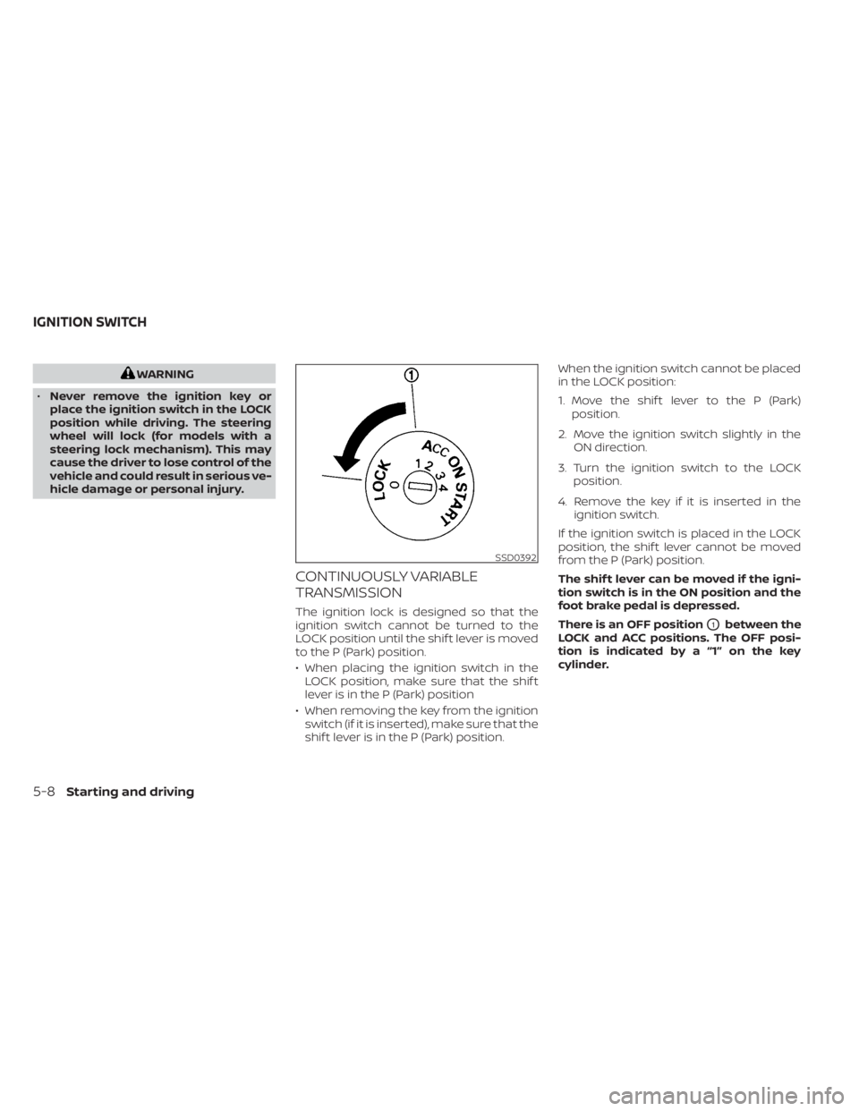
There is an OFF position
O1between the
LOCK and ACC positions. The OFF posi-
tion is indicated by a “1” on the key
cylinder.
Page 153 of 300
ENGINE PROTECTION MODE
The engine has an engine protection mode
to reduce the chance of damage if the
coolant temperature becomes too high
(for example, when climbing steep grades
in high temperature with heavy loads, such
as when towing a trailer). When the engine
temperature reaches a certain level:
• The high temperature warning light willturn on.
• Engine power may be reduced.
• The air conditioning cooling function may be automatically turned off for a short
time (the blower will continue to operate).
Engine power and, under some conditions,
vehicle speed will decrease. Vehicle speed
can be controlled with the accelerator
pedal, but the vehicle may not accelerate at
the desired speed. The transmission will
downshif t or upshif t as it reaches pre-
scribed shif t points. You can also shif t
manually.
As driving conditions change and engine
coolant temperature is reduced, vehicle
speed can be increased using the accel-
erator pedal, and air conditioning cooling
function will automatically be turned back
on. Move the vehicle off the road in a safe area
and allow the engine to cool if the following
occurs:
1. The engine coolant temperature is not
reduced.
2. The air conditioning cooling function does not turn back on.
3. The engine oil pressure low and high temperature warning light
illumi-
nates. This may indicate a malfunction.
If af ter checking the oil and coolant, the
remains on, do not continue to drive. It
is recommended that you visit a NISSAN
dealer for servicing.
The Malfunction Indicator Light (MIL) may
also come ON. If onlyit remains on, you do
not need to have your vehicle towed, but
have it inspected soon. It is recommended
that you visit a NISSAN dealer for this ser-
vice. For additional information, see “Mal-
function Indicator Light (MIL)” (P. 2-14).
CAUTION
Running the engine with the engine oil
pressure warning light on could cause
serious damage to the engine almost
immediately. Such damage is not cov-
ered by warranty. Turn off the engine as
soon as it is safe to do so.
DRIVING THE VEHICLE
Starting and driving5-11