Page 115 of 300
•Do not place the key fob for an ex-
tended period in an area where tem-
peratures exceed 140°F (60°C).
• Do not attach the key fob with a key
holder that contains a magnet.
• Do not place the key fob near equip-
ment that produces a magnetic field,
such as a TV, audio equipment and
personal computers.
If a key fob is lost or stolen, NISSAN rec-
ommends erasing the ID code of that
key fob. This will prevent the key fob
from unauthorized use to unlock the
vehicle. For information regarding the
erasing procedure, it is recommended
that you visit a NISSAN dealer.
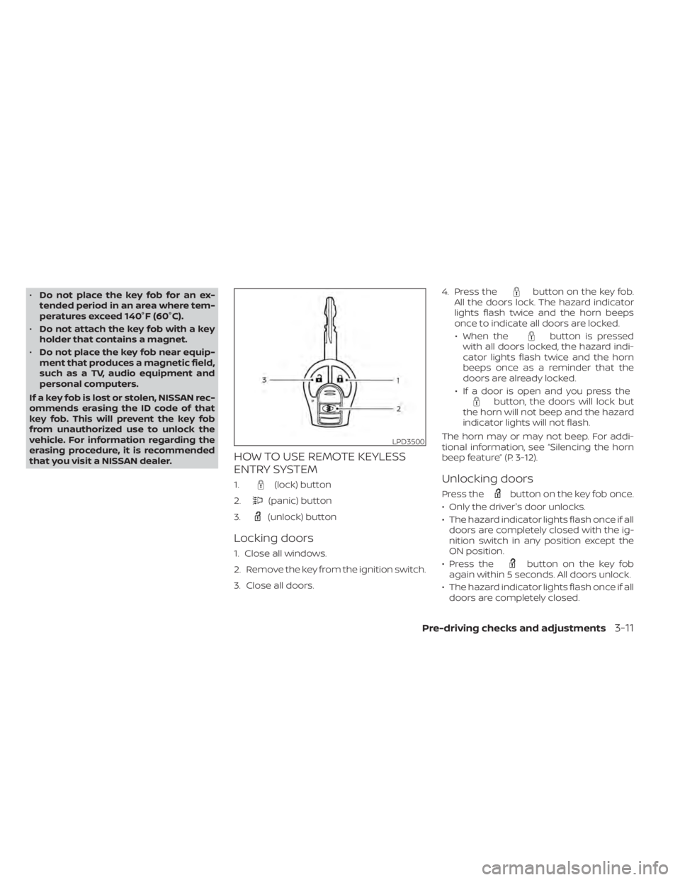
HOW TO USE REMOTE KEYLESS
ENTRY SYSTEM
1.(lock) button
2.
(panic) button
3.
(unlock) button
Locking doors
1. Close all windows.
2. Remove the key from the ignition switch.
3. Close all doors. 4. Press the
button on the key fob.
All the doors lock. The hazard indicator
lights flash twice and the horn beeps
once to indicate all doors are locked.
• When the
button is pressed
with all doors locked, the hazard indi-
cator lights flash twice and the horn
beeps once as a reminder that the
doors are already locked.
• If a door is open and you press the
button, the doors will lock but
the horn will not beep and the hazard
indicator lights will not flash.
The horn may or may not beep. For addi-
tional information, see “Silencing the horn
beep feature” (P. 3-12).
Unlocking doors
Press thebutton on the key fob once.
• Only the driver's door unlocks.
• The hazard indicator lights flash once if all doors are completely closed with the ig-
nition switch in any position except the
ON position.
• Press the
button on the key fob
again within 5 seconds. All doors unlock.
• The hazard indicator lights flash once if all doors are completely closed.
LPD3500
Page 116 of 300
button on the key fob once
to turn on the interior lights.
The interior lights can be turned off without
waiting a period of time by inserting the key
into the ignition switch and placing the ig-
nition switch in the ON or START position,
locking the doors with the key fob, power
door lock switch or pushing the interior
light switch to the OFF position.
For additional information, see
lightsŽ (P. 2-32).
Auto relock
When thebutton on the key fob is
pressed, all doors will lock automatically
within one minute unless one of the follow-
ing operations is performed:
€ Any door is opened.
€ A key is inserted into the ignition switch and the switch is cycled from OFF to ON.
€ Press key fob
button.
Using the panic alarm
If you are near your vehicle and feel threat-
ened, you may activate the panic alarm to call attention by pressing and holding the
button on the key fob for
longer than
0.5 seconds.
The panic alarm and headlights will stay on
for a period of time.
The panic alarm stops when:
• It has run for a period of time.
• Any button is pressed on the key fob.
Silencing the horn beep feature
If desired, the horn beep feature can be
deactivated using the key fob.
To deactivate: Press and hold the
andbuttonsfor at least 2 seconds.
The hazard indicator lights will flash three
times to confirm that the horn beep fea-
ture has been deactivated.
To activate: Press and hold the
andbuttonsfor at least 2 seconds once
more.
The hazard indicator lights will flash once
and the horn will sound once to confirm
that the horn beep feature has been
reactivated.
Deactivating the horn beep feature does
not silence the horn if the alarm is
triggered.
3-12Pre-driving checks and adjustments
Page 117 of 300
1. Pull the hood lock release handleOElo-
cated below the instrument panel until
the hood springs up slightly.
2. Locate the lever
OAin between the hood
and grille and push the lever sideways
with your fingertips.
3. Raise the hood
OB.
4. Remove the support rod
OCand insert it
into the slot
OD. Hold the coated parts of the support rod
when removing or resetting the support
rod. Avoid direct contact with the metal
parts, as they may be hot immediately
af ter the engine has been stopped.
When closing the hood, return the support
rod to its original position, lower the hood
to approximately 12 in (30 cm) above the
latch and release it. This allows proper en-
gagement of the hood latch.
Pre-driving checks and adjustments3-13
Page 118 of 300
OPENER OPERATION
The fuel-filler door release is located below
the instrument panel. To open the fuel-filler
door, pull the release. To lock, close the fuel-
filler door securely.
FUEL-FILLER CAP
Malfunc-
tion Indicator Light (MIL) to come on.
• Never pour fuel into the throttle body
to attempt to start your vehicle. •
Do not fill a portable fuel container in
the vehicle or trailer. Static electricity
can cause an explosion of flammable
liquid, vapor or gas in any vehicle or
trailer. To reduce the risk of serious
injury or death when filling portable
fuel containers:
– Always place the container on the
ground when filling.
– Do not use electronic devices
when filling.
– Keep the pump nozzle in contact
with the container while you are
filling it.
– Use only approved portable fuel
containers for flammable liquid.
CAUTION
• Do not use E-15 or E-85 in your ve-
hicle. For additional information, see
“Fuel Recommendation” (P. 10-3).
Page 119 of 300
•Failure to tighten the fuel-filler cap
properly may cause theMal-
function Indicator Light (MIL) to illu-
minate. If the
light illuminates
because the fuel-filler cap is loose or
missing, tighten or install the cap and
continue to drive the vehicle. The
light should turn off af ter a few
driving trips. If thelight does not
turn off af ter a few driving trips, have
the vehicle inspected. It is recom-
mended that you visit a NISSAN
dealer for this service.
• The LOOSE FUEL CAP warning mes-
sage will be displayed if the fuel-filler
cap is not properly tightened. It may
take a few driving trips for the mes-
sage to be displayed. Failure to
tighten the fuel-filler cap properly af-
ter the LOOSE FUEL CAP warning
message is displayed may cause the
Malfunction Indicator Light (MIL)
to illuminate.
• For additional information, “Malfunc-
tion Indicator Light (MIL)” (P. 2-14).
• If fuel is spilled on the vehicle body,
flush it away with water to avoid
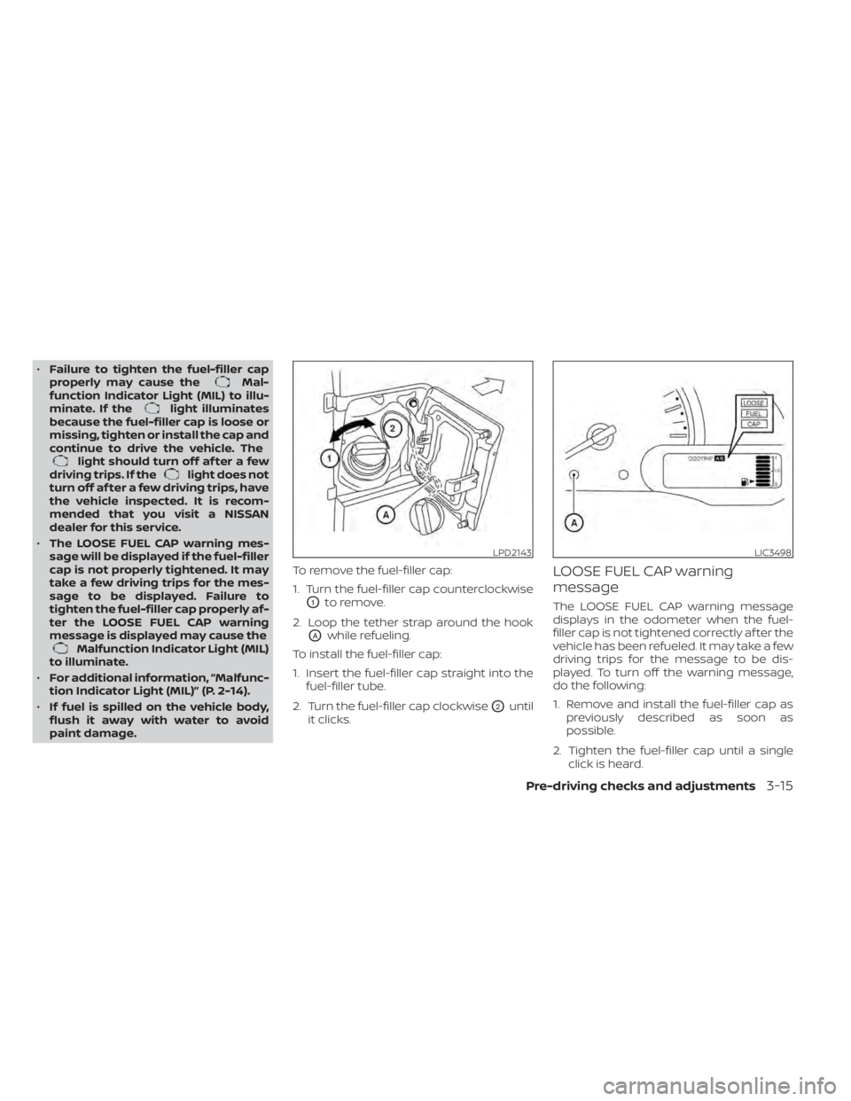
paint damage. To remove the fuel-filler cap:
1. Turn the fuel-filler cap counterclockwise
O1to remove.
2. Loop the tether strap around the hook
OAwhile refueling.
To install the fuel-filler cap:
1. Insert the fuel-filler cap straight into the fuel-filler tube.
2. Turn the fuel-filler cap clockwise
O2until
it clicks.
LOOSE FUEL CAP warning
message
The LOOSE FUEL CAP warning message
displays in the odometer when the fuel-
filler cap is not tightened correctly af ter the
vehicle has been refueled. It may take a few
driving trips for the message to be dis-
played. To turn off the warning message,
do the following:
1. Remove and install the fuel-filler cap as previously described as soon as
possible.
2. Tighten the fuel-filler cap until a single click is heard.
LPD2143LIC3498
Page 121 of 300
CARD HOLDER (driver's side only)
To access the card holder, pull the sun visor
down and slide card in the card holder
OA.
Do not view information while operating
the vehicle.
MANUAL ANTI-GLARE REARVIEW
MIRROR (if so equipped)
Use the night positionO1to reduce glare
from the headlights of vehicles behind you
at night.
Use the day position
O2when driving in
daylight hours.
WPD0126
MIRRORS
Pre-driving checks and adjustments3-17
Page 131 of 300
•When washing the vehicle with high
pressure water, be sure not to spray it
around the camera. Otherwise, water
may enter the camera unit causing
water condensation on the lens, a
malfunction, fire or an electric shock.
• Do not strike the camera. It is a preci-
sion instrument. Otherwise, it may
malfunction or cause damage result-
ing in a fire or an electric shock.
The following are operating limitations and
do not represent a system malfunction:
• When the temperature is extremely high or low, the screen may not clearly display
objects.
• When strong light directly shines on the camera, objects may not be displayed
clearly.
• Vertical lines may be seen in objects on the screen. This is due to strong reflected
light from the bumper.
• The screen may flicker under fluorescent light.
• The colors of objects on the RearView Monitor may differ somewhat from the
actual color of objects.
• Objects on the monitor may not be clear in a dark environment. • There may be a delay when switching
between views.
• If dirt, rain or snow accumulate on the camera, the RearView Monitor may not
display objects clearly. Clean the camera.
• Do not use wax on the camera lens. Wipe off any wax with a clean cloth dampened
with a diluted mild cleaning agent, then
wipe with a dry cloth.
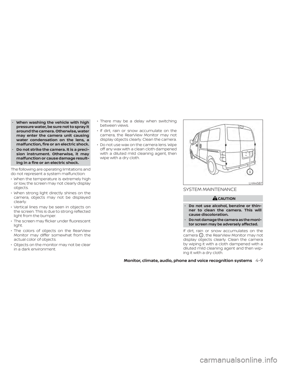
SYSTEM MAINTENANCE
LHA4587
Page 134 of 300
fan speed
control dial to the desired position and
press the
button to turn on the air
conditioner. To turn off the air conditioner,
press the
button again.
The air conditioner cooling function op-
erates only when the engine is running.
Rear window and/or outside
mirror defroster switch (if so
equipped)
For additional information, see “Rear win-
dow and/or outside mirror defroster
switch (if so equipped)” (P. 2-21).
HEATER OPERATION
Heating
This mode is used to direct heated air to
the foot outlets. Some air also flows from
the defrost outlets.
1. Move the air intake lever to the
position for normal heating.
2. Turn the air flow control dial to the
position. 3. Turn the
fan speed control dial to
the desired position.
4. Turn the temperature control dial to the desired position between the middle
and the hot position.
Ventilation
This mode directs outside air to the side
and center vents.
1. Move the air intake lever to the
position.
2. Turn the air flow control dial to the
position.
3. Turn the
fan speed control dial to
the desired position.
4. Turn the temperature control dial to the desired position.
Defrosting or defogging
This mode directs the air to the defrost
outlets to defrost/defog the windows.
1. Move the air intake lever to the
position.
2. Turn the air flow control dial to the
position. 3. Turn the
fan speed control dial to
the desired position.
4. Turn the temperature control dial to the desired position between the middle
and the hot position.
• To quickly remove ice or fog from the win- dows, turn the
fan speed control dial
to the maximum position and the tem-
perature control dial to the full hot
position.
When the
orposition is se-
lected, the air conditioner automatically
turns on (however, the indicator light will
not illuminate). In this position, the air con-
ditioner cannot be turned off. When the air
flow control is turned to any position other
than
or(the air conditioner will
continue operating). and can be turned off
using the air conditioner button. This dehu-
midifies the air, which helps defog the
windshield.
Bi-level heating
This mode directs cooler air from the side
and center vents and warmer air from the
floor outlets. When the temperature con-
trol dial is moved to the full hot or full cool
position, the air between the vents and the
floor outlets is the same temperature.
4-12Monitor, climate, audio, phone and voice recognition systems