2021 NISSAN MURANO lock
[x] Cancel search: lockPage 197 of 508
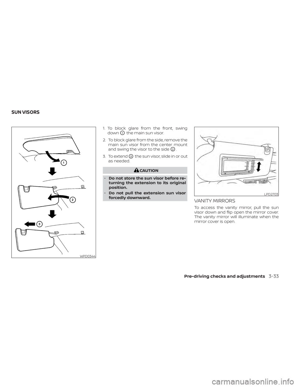
1. To block glare from the front, swingdown
O1the main sun visor.
2. To block glare from the side, remove the main sun visor from the center mount
and swing the visor to the side
O2.
3. To extend
O3the sun visor, slide in or out
as needed.
CAUTION
• Do not store the sun visor before re-
turning the extension to its original
position.
• Do not pull the extension sun visor
forcedly downward.
VANITY MIRRORS
To access the vanity mirror, pull the sun
visor down and flip open the mirror cover.
The vanity mirror will illuminate when the
mirror cover is open.
WPD0344
LPD2703
SUN VISORS
Pre-driving checks and adjustments3-33
Page 201 of 508

The memory seat system has three
features:
• Memory storage function (Key-link)
• Memory storage function (Switch)
• Entry/exit function
Key-link, when enabled, automatically re-
tains the driver’s last seat, outside mirrors
and steering wheel (if so equipped) posi-
tions for that specific key when the ignition
is turned from ON to OFF.
Each memory switch button (1 or 2) on the
driver’s door can also store one additional
position which is independent of the key-
linked position.
MEMORY STORAGE FUNCTION
(key-link)
Use the following process to setup key-link:
1. Unlock the vehicle with the desired Intel-ligent Key while the ignition is OFF.
2. Place the ignition in the ON position.
3. Within the “Settings” menu of the vehicle information display, select “Key-Linked
Settings” and press the OK button on the
steering switch. 4. While in the menu, press the OK button
on the steering switch to turn the sys-
tem ON/OFF.
Once step 4 is completed, every time the
ignition is switched from ON to OFF, the
memory positions of the driver’s seat, out-
side mirrors and automatic steering wheel
(if so equipped) are linked to the Intelligent
Key.
Follow the same procedure if you want
to link the 2nd, 3rd or 4th Intelligent Key.
NOTE:
If new memory positions are set prior to
turning the ignition from ON to OFF, the
previously linked memory positions for
the respective key will be overwritten by
new positions.
Recalling Intelligent Key memory
positions
If the “Key-Linked Settings” are enabled in
the vehicle information display for that par-
ticular key, every time you enter the vehicle
the driver’s seat, mirrors and automatic
steering wheel (if so equipped) will auto-
matically move to the driver’s last position
of the respective Intelligent Key.
NOTE:
The key-linked memory positions can be
different from the positions stored in the
memory switch (1 or 2).
MEMORY SEAT (if so equipped)
Pre-driving checks and adjustments3-37
Page 210 of 508
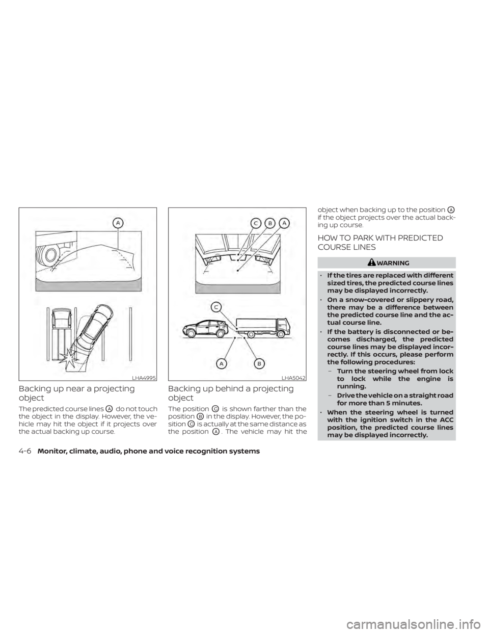
Backing up near a projecting
object
The predicted course linesOAdo not touch
the object in the display. However, the ve-
hicle may hit the object if it projects over
the actual backing up course.
Backing up behind a projecting
object
The positionOCis shown farther than the
position
OBin the display. However, the po-
sition
OCis actually at the same distance as
the position
OA. The vehicle may hit the object when backing up to the position
OA
if the object projects over the actual back-
ing up course.
HOW TO PARK WITH PREDICTED
COURSE LINES
WARNING
• If the tires are replaced with different
sized tires, the predicted course lines
may be displayed incorrectly.
• On a snow-covered or slippery road,
there may be a difference between
the predicted course line and the ac-
tual course line.
• If the battery is disconnected or be-
comes discharged, the predicted
course lines may be displayed incor-
rectly. If this occurs, please perform
the following procedures:
– Turn the steering wheel from lock
to lock while the engine is
running.
– Drive the vehicle on a straight road
for more than 5 minutes.
• When the steering wheel is turned
with the ignition switch in the ACC
position, the predicted course lines
may be displayed incorrectly.
LHA4995LHA5042
4-6Monitor, climate, audio, phone and voice recognition systems
Page 220 of 508
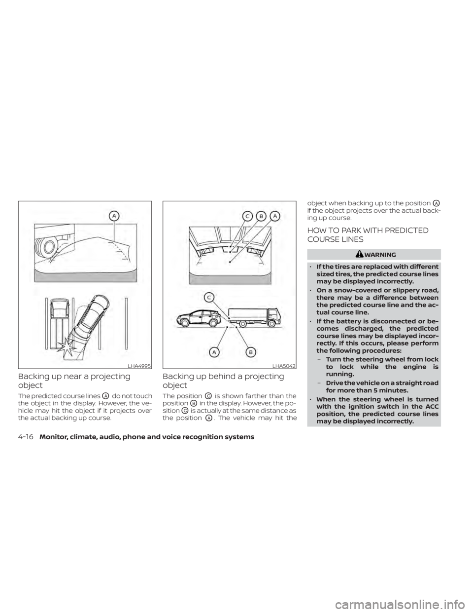
Backing up near a projecting
object
The predicted course linesOAdo not touch
the object in the display. However, the ve-
hicle may hit the object if it projects over
the actual backing up course.
Backing up behind a projecting
object
The positionOCis shown farther than the
position
OBin the display. However, the po-
sition
OCis actually at the same distance as
the position
OA. The vehicle may hit the object when backing up to the position
OA
if the object projects over the actual back-
ing up course.
HOW TO PARK WITH PREDICTED
COURSE LINES
WARNING
• If the tires are replaced with different
sized tires, the predicted course lines
may be displayed incorrectly.
• On a snow-covered or slippery road,
there may be a difference between
the predicted course line and the ac-
tual course line.
• If the battery is disconnected or be-
comes discharged, the predicted
course lines may be displayed incor-
rectly. If this occurs, please perform
the following procedures:
– Turn the steering wheel from lock
to lock while the engine is
running.
– Drive the vehicle on a straight road
for more than 5 minutes.
• When the steering wheel is turned
with the ignition switch in the ACC
position, the predicted course lines
may be displayed incorrectly.
LHA4995LHA5042
4-16Monitor, climate, audio, phone and voice recognition systems
Page 229 of 508
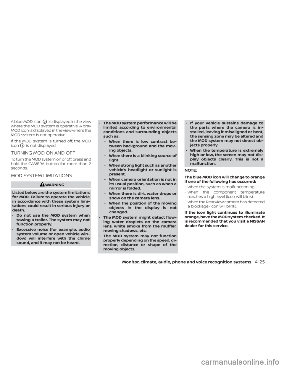
A blue MOD iconO3is displayed in the view
where the MOD system is operative. A gray
MOD icon is displayed in the view where the
MOD system is not operative.
If the MOD system is turned off, the MOD
icon
O3is not displayed.
TURNING MOD ON AND OFF
To turn the MOD system on or off, press and
hold the CAMERA button for more than 2
seconds.
MOD SYSTEM LIMITATIONS
WARNING
Listed below are the system limitations
for MOD. Failure to operate the vehicle
in accordance with these system limi-
tations could result in serious injury or
death.
• Do not use the MOD system when
towing a trailer. The system may not
function properly.
• Excessive noise (for example, audio
system volume or open vehicle win-
dow) will interfere with the chime
sound, and it may not be heard. •
The MOD system performance will be
limited according to environmental
conditions and surrounding objects
such as:
– When there is low contrast be-
tween background and the mov-
ing objects.
– When there is a blinking source of
light.
– When strong light such as another
vehicle’s headlight or sunlight is
present.
– When camera orientation is not in
its usual position, such as when a
mirror is folded.
– When there is dirt, water drops or
snow on the camera lens.
– When the position of the moving
objects in the display is not
changed.
• The MOD system might detect flow-
ing water droplets on the camera
lens, white smoke from the muffler,
moving shadows, etc.
• The MOD system may not function
properly depending on the speed, di-
rection, distance or shape of the
moving objects. •
If your vehicle sustains damage to
the parts where the camera is in-
stalled, leaving it misaligned or bent,
the sensing zone may be altered and
the MOD system may not detect ob-
jects properly.
• When the temperature is extremely
high or low, the screen may not dis-
play objects clearly. This is not a
malfunction.
NOTE:
The blue MOD icon will change to orange
if one of the following has occurred:
• When the system is malfunctioning.
• When the component temperature reaches a high level (icon will blink).
• When the RearView camera has detected a blockage (icon will blink).
If the icon light continues to illuminate
orange, have the MOD system checked. It
is recommended that you visit a NISSAN
dealer for this service.
Monitor, climate, audio, phone and voice recognition systems4-25
Page 241 of 508
System malfunction........................ 5-107
System maintenance ......................5-108
Intelligent Driver Alertness (I-DA) ...............5-109
Intelligent Driver Alertness system
operation .................................. 5-110
How to enable/disable the Intelligent
Driver Alertness (I-DA) system ...............5-111
Intelligent Driver Alertness (I-DA)
system limitations .......................... 5-111
Break-in schedule ............................. 5-113
Fuel efficient driving tips .......................5-113
Increasing fuel economy ......................5-114
All-Wheel Drive (AWD) (if so equipped) ..........5-114
Parking/parking on hills ........................5-117
Power steering ................................ 5-118
Brake system ................................. 5-119
Brake precautions .......................... 5-119Anti-lock Braking System (ABS)
.............5-119
Brake Assist ................................ 5-121
Vehicle Dynamic Control (VDC) system ........5-121
Rise-up and build-up ....................... 5-122
Brake force distribution ....................5-123
Hill start assist system ........................5-124
Front and rear sonar system (if so equipped) . . 5-124 How to enable/disable the front and
rear sonar system .......................... 5-126
Cold weather driving .......................... 5-127
Freeing a frozen door lock ..................5-127
Antifreeze .................................. 5-127
Battery..................................... 5-127
Draining of coolant water ..................5-127
Tire equipment ............................. 5-127
Special winter equipment ..................5-127
Driving on snow or ice ......................5-127
Page 251 of 508
•Whenever you drive off-road through
sand, mud or water as deep as the
wheel hub, more frequent mainte-
nance may be required. For addi-
tional information, see “Maintenance
schedules” (P. 9-7).
WARNING
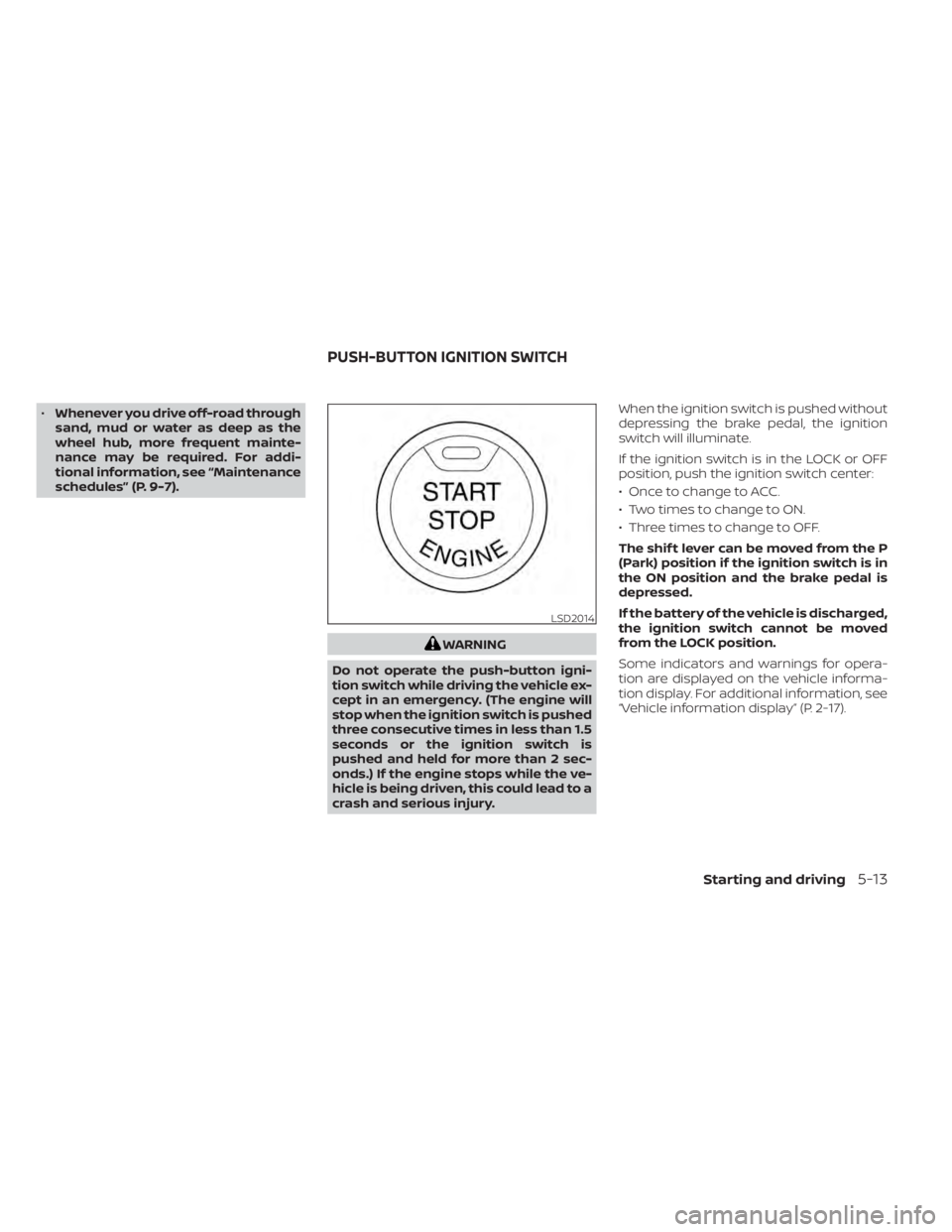
Do not operate the push-button igni-
tion switch while driving the vehicle ex-
cept in an emergency. (The engine will
stop when the ignition switch is pushed
three consecutive times in less than 1.5
seconds or the ignition switch is
pushed and held for more than 2 sec-
onds.) If the engine stops while the ve-
hicle is being driven, this could lead to a
crash and serious injury. When the ignition switch is pushed without
depressing the brake pedal, the ignition
switch will illuminate.
If the ignition switch is in the LOCK or OFF
position, push the ignition switch center:
• Once to change to ACC.
• Two times to change to ON.
• Three times to change to OFF.
The shif t lever can be moved from the P
(Park) position if the ignition switch is in
the ON position and the brake pedal is
depressed.
If the battery of the vehicle is discharged,
the ignition switch cannot be moved
from the LOCK position.
Some indicators and warnings for opera-
tion are displayed on the vehicle informa-
tion display. For additional information, see
“Vehicle information display” (P. 2-17).
LSD2014
PUSH-BUTTON IGNITION SWITCH
Starting and driving5-13
Page 252 of 508
OPERATING RANGE
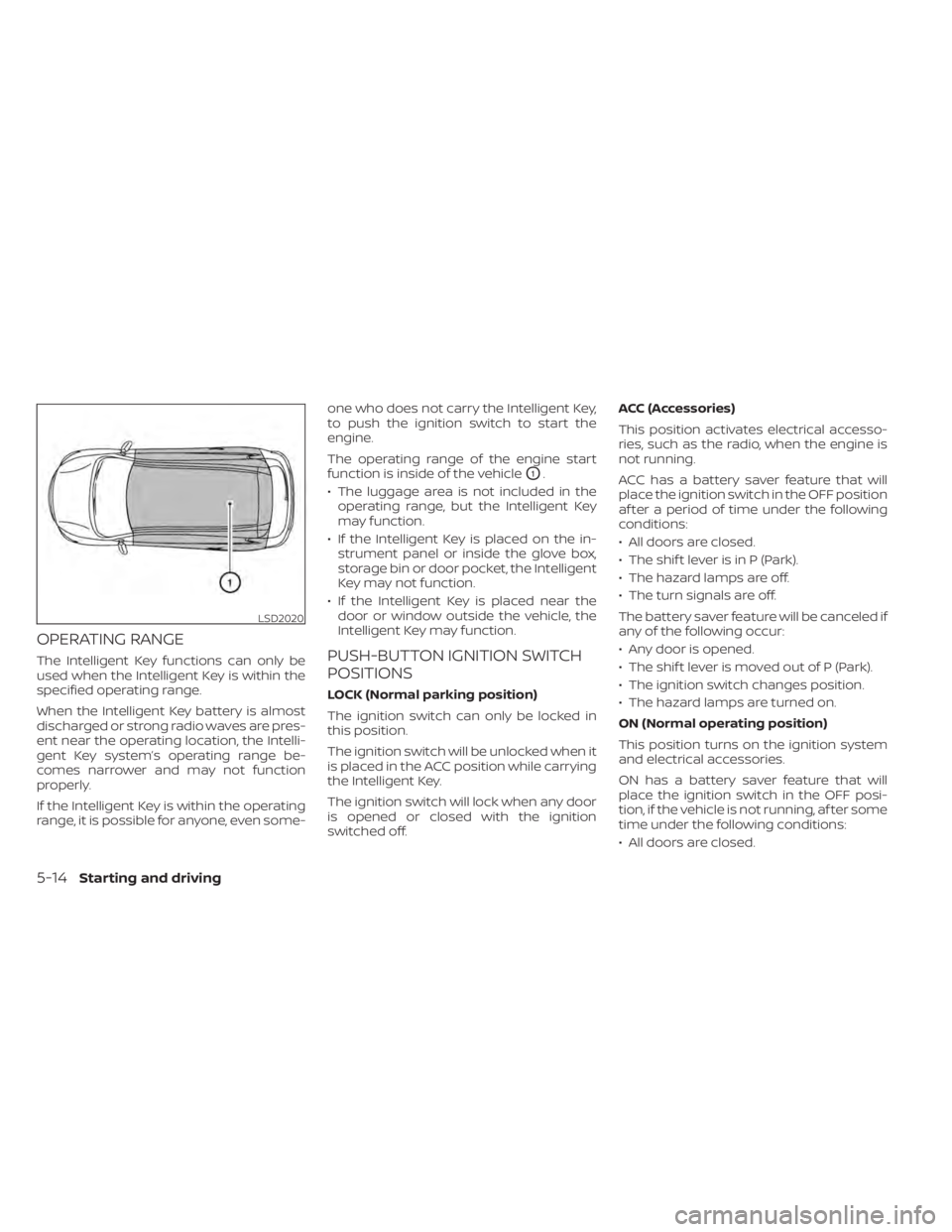
The Intelligent Key functions can only be
used when the Intelligent Key is within the
specified operating range.
When the Intelligent Key battery is almost
discharged or strong radio waves are pres-
ent near the operating location, the Intelli-
gent Key system’s operating range be-
comes narrower and may not function
properly.
If the Intelligent Key is within the operating
range, it is possible for anyone, even some-one who does not carry the Intelligent Key,
to push the ignition switch to start the
engine.
The operating range of the engine start
function is inside of the vehicle
O1.
• The luggage area is not included in the operating range, but the Intelligent Key
may function.
• If the Intelligent Key is placed on the in- strument panel or inside the glove box,
storage bin or door pocket, the Intelligent
Key may not function.
• If the Intelligent Key is placed near the door or window outside the vehicle, the
Intelligent Key may function.
PUSH-BUTTON IGNITION SWITCH
POSITIONS
LOCK (Normal parking position)
The ignition switch can only be locked in
this position.
The ignition switch will be unlocked when it
is placed in the ACC position while carrying
the Intelligent Key.
The ignition switch will lock when any door
is opened or closed with the ignition
switched off. ACC (Accessories)
This position activates electrical accesso-
ries, such as the radio, when the engine is
not running.
ACC has a battery saver feature that will
place the ignition switch in the OFF position
af ter a period of time under the following
conditions:
• All doors are closed.
• The shif t lever is in P (Park).
• The hazard lamps are off.
• The turn signals are off.
The battery saver feature will be canceled if
any of the following occur:
• Any door is opened.
• The shif t lever is moved out of P (Park).
• The ignition switch changes position.
• The hazard lamps are turned on.
ON (Normal operating position)
This position turns on the ignition system
and electrical accessories.
ON has a battery saver feature that will
place the ignition switch in the OFF posi-
tion, if the vehicle is not running, af ter some
time under the following conditions:
• All doors are closed.
LSD2020
5-14Starting and driving