2021 NISSAN FRONTIER ignition
[x] Cancel search: ignitionPage 105 of 492
inflate if the forces in another type of colli-
sion are similar to those of a higher severity
impact. They are designed to inflate on the
side where the vehicle is impacted. They
may not inflate in certain side collisions.
Curtain air bags are also designed to inflate in
certain types of rollover collisions or near roll-
overs. As a result, certain vehicle movements
(for example, during severe off-roading) may
cause the curtain air bags to inflate.
Vehicle damage (or lack of it) is not always
an indication of proper side air bag and
curtain air bag operation.
When the side air bags and curtain air bags
inflate, a fairly loud noise may be heard,
followed by release of smoke. This smoke is
not harmful and does not indicate a fire.
Care should be taken not to inhale it, as it
may cause irritation and choking. Those
with a history of a breathing condition
should get fresh air promptly.
Side air bags, along with the use of seat
belts, help to cushion the impact force on
the chest and pelvic area of the front occu-
pants. Curtain air bags help to cushion the
impact force to the head of occupants in
the front and rear outboard seating posi-
tions. They can help save lives and reduce
serious injuries. However, an inflating sideair bag or curtain air bag may cause abra-
sions or other injuries. Side air bags and
curtain air bags do not provide restraint to
the lower body.
The seat belts should be correctly worn
and the driver and passenger seated up-
right as far as practical away from the side
air bag. Rear seat passengers should be
seated as far away as practical from the
door finishers and side roof rails. The side
air bags and curtain air bags inflate quickly
in order to help protect the occupants. Be-
cause of this, the force of the side air bag
and curtain air bag inflating can increase
the risk of injury if the occupant is too close
to, or is against, these air bag modules dur-
ing inflation. The side air bag will deflate
quickly af ter the collision is over.
The curtain air bags will remain inflated for
a short time.
The side air bags and curtain air bags
operate only when the ignition switch is
in the ON or START position.
Af ter placing the ignition switch in the
ON position, the supplemental air bag
warning light illuminates. The supple-
mental air bag warning light will turn off
af ter about 7 seconds if the system is
operational.
WARNING
• Do not place any objects near the
seatback of the front seats. Also, do
not place any objects (an umbrella,
bag, etc.) between the front door fin-
isher and the front seat. Such objects
may become dangerous projectiles
and cause injury if a side air bag
inflates.
• Right af ter inflation, several side air
bag and curtain air bag system com-
ponents will be hot. Do not touch
them; you may severely burn
yourself.
• No unauthorized changes should be
made to any components or wiring
of the side air bag and curtain air bag
systems. This is to prevent damage
to or accidental inflation of the side
air bag and curtain air bag systems.
• Do not make unauthorized changes
to your vehicle's electrical system,
suspension system or side panel.
This could affect proper operation of
the curtain air bag systems.
Safety-Seats, seat belts and supplemental restraint system1-83
Page 107 of 492
When pretensioner(s) activate, smoke is re-
leased and a loud noise may be heard. This
smoke is not harmful and does not indi-
cate a fire. Care should be taken not to
inhale it, as it may cause irritation and
choking. Those with a history of a breath-
ing condition should get fresh air promptly.
Af ter the pretensioner(s’) activation, load
limiters allow the seat belt to release web-
bing (if necessary) to reduce forces against
the chest.
The supplemental air bag warning light
is used to indicate malfunctions in the
pretensioner system. For additional infor-
mation, refer to "Supplemental air bag
warning light" in this section. If the opera-
tion of the supplemental air bag warning
light indicates there is a malfunction, have
the system checked. It is recommended
that you visit a NISSAN dealer for this ser-
vice.
When selling your vehicle, we request that
you inform the buyer about the preten-
sioner system and guide the buyer to the
appropriate sections in this Owner's
Manual.
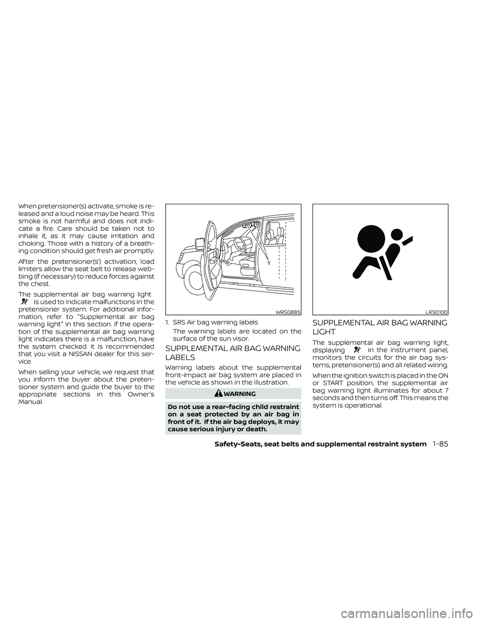
SUPPLEMENTAL AIR BAG WARNING
LABELS
Warning labels about the supplemental
front-impact air bag system are placed in
the vehicle as shown in the illustration.
in the instrument panel,
monitors the circuits for the air bag sys-
tems, pretensioner(s) and all related wiring.
When the ignition switch is placed in the ON
or START position, the supplemental air
bag warning light illuminates for about 7
seconds and then turns off. This means the
system is operational.
WRS0885
1. SRS Air bag warning labels
The warning labels are located on the
surface of the sun visor.
LRS0100
Page 113 of 492
16. Shif t lever (P. 5-14)
17. Push-button ignition switch (P. 5-10)
18. 4WD shif t switch (if so equipped)(P. 5-23)
19. Climate controls (P. 4-22, P. 4-31)
20. Hazard warning flasher switch (P. 6-2)
21. Tilt steering wheel control (P. 3-16)
22. Cargo lamp switch (P. 2-34) Hill descent control switch
(if so equipped) (P. 2-36)
Outside mirror controls (if so equipped)
(P. 3-17)
Instruments and controls2-3
Page 115 of 492
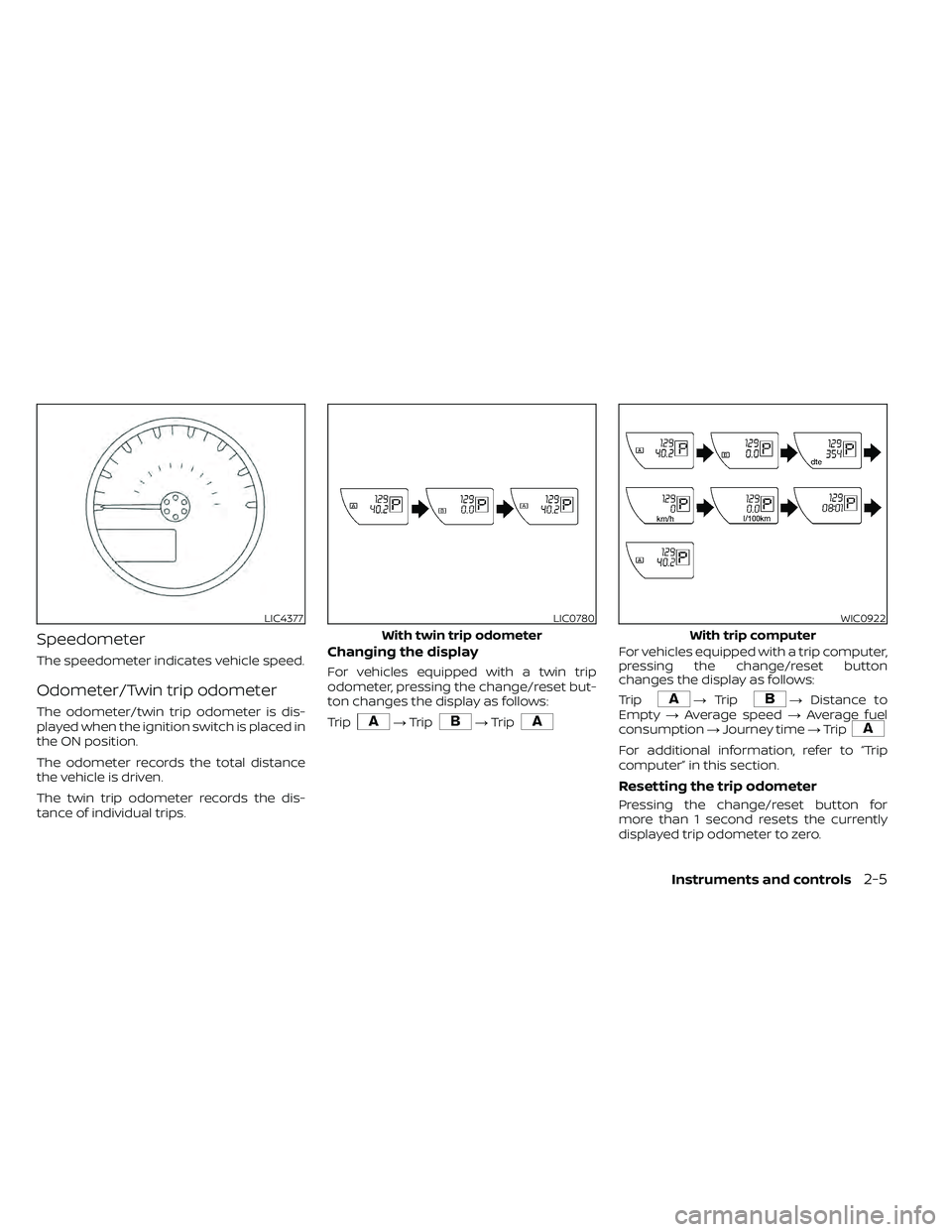
Speedometer
The speedometer indicates vehicle speed.
Odometer/Twin trip odometer
The odometer/twin trip odometer is dis-
played when the ignition switch is placed in
the ON position.
The odometer records the total distance
the vehicle is driven.
The twin trip odometer records the dis-
tance of individual trips.
Changing the display
For vehicles equipped with a twin trip
odometer, pressing the change/reset but-
ton changes the display as follows:
Trip
For vehicles equipped with a trip computer,
pressing the change/reset button
changes the display as follows:
Trip
For additional information, refer to “Trip
computer” in this section.
Resetting the trip odometer
Pressing the change/reset button for
more than 1 second resets the currently
displayed trip odometer to zero.
LIC4377LIC0780
With twin trip odometer
Instruments and controls2-5
Page 116 of 492
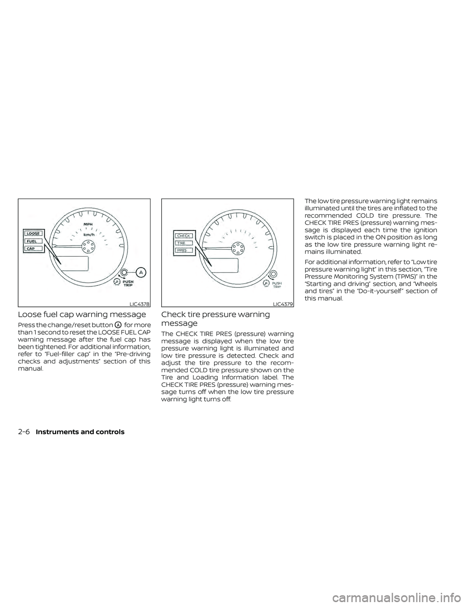
Loose fuel cap warning message
Press the change/reset buttonOAfor more
than 1 second to reset the LOOSE FUEL CAP
warning message af ter the fuel cap has
been tightened. For additional information,
refer to “Fuel-filler cap” in the “Pre-driving
checks and adjustments” section of this
manual.
Check tire pressure warning
message
The CHECK TIRE PRES (pressure) warning
message is displayed when the low tire
pressure warning light is illuminated and
low tire pressure is detected. Check and
adjust the tire pressure to the recom-
mended COLD tire pressure shown on the
Tire and Loading Information label. The
CHECK TIRE PRES (pressure) warning mes-
sage turns off when the low tire pressure
warning light turns off. The low tire pressure warning light remains
illuminated until the tires are inflated to the
recommended COLD tire pressure. The
CHECK TIRE PRES (pressure) warning mes-
sage is displayed each time the ignition
switch is placed in the ON position as long
as the low tire pressure warning light re-
mains illuminated.
For additional information, refer to “Low tire
pressure warning light” in this section, “Tire
Pressure Monitoring System (TPMS)” in the
“Starting and driving” section, and “Wheels
and tires” in the “Do-it-yourself ” section of
this manual.
LIC4378LIC4379
2-6Instruments and controls
Page 118 of 492
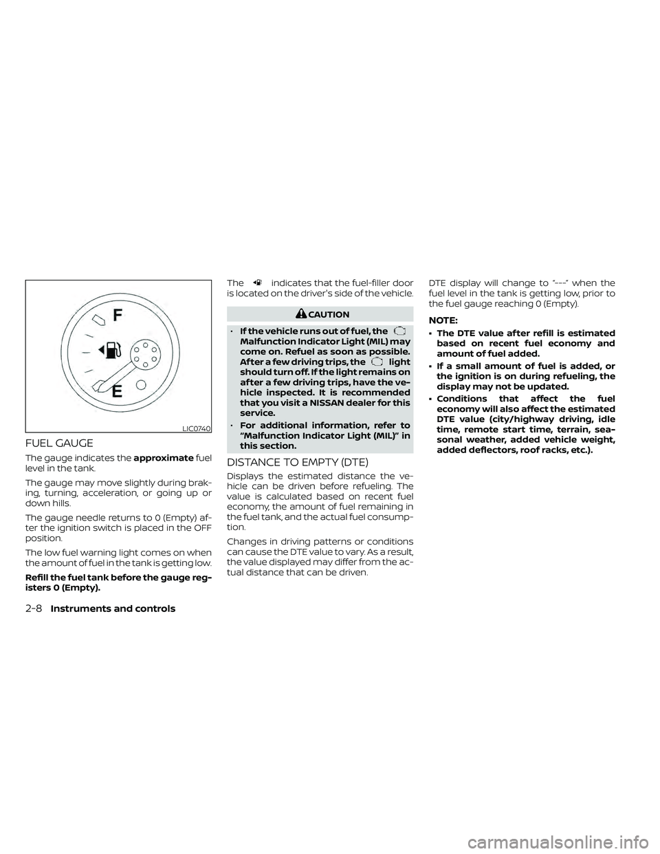
FUEL GAUGE
The gauge indicates theapproximatefuel
level in the tank.
The gauge may move slightly during brak-
ing, turning, acceleration, or going up or
down hills.
The gauge needle returns to 0 (Empty) af-
ter the ignition switch is placed in the OFF
position.
The low fuel warning light comes on when
the amount of fuel in the tank is getting low.
Refill the fuel tank before the gauge reg-
isters 0 (Empty). The
indicates that the fuel-filler door
is located on the driver's side of the vehicle.
Malfunction Indicator Light (MIL) may
come on. Refuel as soon as possible.
Af ter a few driving trips, the
light
should turn off. If the light remains on
af ter a few driving trips, have the ve-
hicle inspected. It is recommended
that you visit a NISSAN dealer for this
service.
• For additional information, refer to
“Malfunction Indicator Light (MIL)” in
this section.
DISTANCE TO EMPTY (DTE)
Displays the estimated distance the ve-
hicle can be driven before refueling. The
value is calculated based on recent fuel
economy, the amount of fuel remaining in
the fuel tank, and the actual fuel consump-
tion.
Changes in driving patterns or conditions
can cause the DTE value to vary. As a result,
the value displayed may differ from the ac-
tual distance that can be driven. DTE display will change to “---” when the
fuel level in the tank is getting low, prior to
the fuel gauge reaching 0 (Empty).
NOTE:
• The DTE value af ter refill is estimated
based on recent fuel economy and
amount of fuel added.
• If a small amount of fuel is added, or the ignition is on during refueling, the
display may not be updated.
• Conditions that affect the fuel economy will also affect the estimated
DTE value (city/highway driving, idle
time, remote start time, terrain, sea-
sonal weather, added vehicle weight,
added deflectors, roof racks, etc.).
2-8Instruments and controls
Page 119 of 492
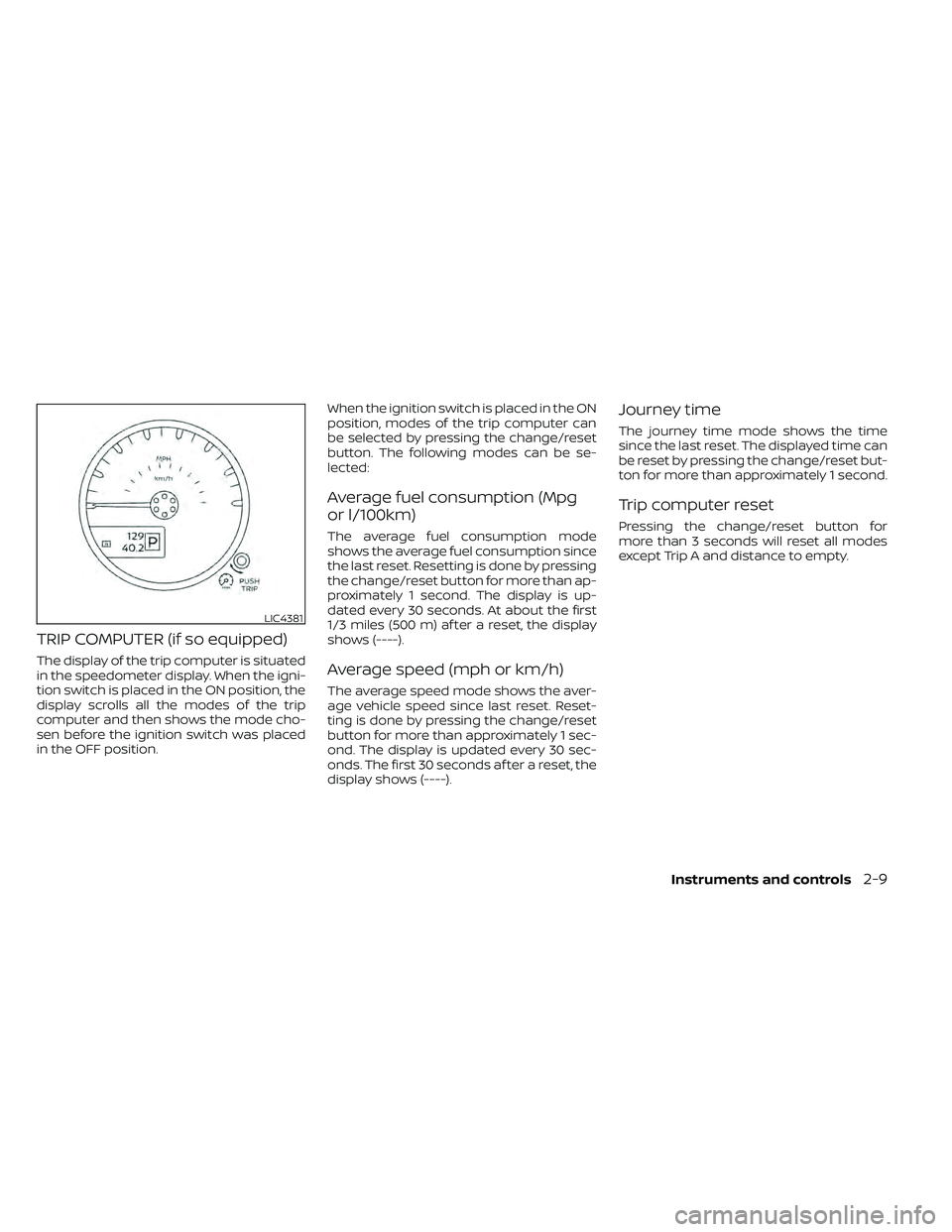
TRIP COMPUTER (if so equipped)
The display of the trip computer is situated
in the speedometer display. When the igni-
tion switch is placed in the ON position, the
display scrolls all the modes of the trip
computer and then shows the mode cho-
sen before the ignition switch was placed
in the OFF position.When the ignition switch is placed in the ON
position, modes of the trip computer can
be selected by pressing the change/reset
button. The following modes can be se-
lected:
Average fuel consumption (Mpg
or l/100km)
The average fuel consumption mode
shows the average fuel consumption since
the last reset. Resetting is done by pressing
the change/reset button for more than ap-
proximately 1 second. The display is up-
dated every 30 seconds. At about the first
1/3 miles (500 m) af ter a reset, the display
shows (----).
Average speed (mph or km/h)
The average speed mode shows the aver-
age vehicle speed since last reset. Reset-
ting is done by pressing the change/reset
button for more than approximately 1 sec-
ond. The display is updated every 30 sec-
onds. The first 30 seconds af ter a reset, the
display shows (----).
Journey time
The journey time mode shows the time
since the last reset. The displayed time can
be reset by pressing the change/reset but-
ton for more than approximately 1 second.
Trip computer reset
Pressing the change/reset button for
more than 3 seconds will reset all modes
except Trip A and distance to empty.
LIC4381
Page 120 of 492
This unit has the following functions:
• Measures terrestrial magnetism and in-dicates the heading direction of the ve-
hicle
• Indicates outside air temperature
With the ignition switch in the ON position,
press the
orbutton as described
in the charts below to activate various fea-
tures of the automatic anti-glare rearview
mirror.
Type A (if so equipped)
button for
about: Feature:
(Press button again for about 1
second to change settings)
1 second Compass toggles on/off
8 seconds Automatic anti-glare/indicator
light toggles on/off
11 seconds Compass zone can be changed
to correct false compass read-
ings
13 seconds Compass enters calibration
mode
Type B (if so equipped)
button for
about:Feature:
(Press button again for about 1
second to change settings)
1 second Compass toggles on/off
8 seconds Compass zone can be changed
to correct false compass read-
ings
10 seconds Compass enters calibration
mode
For additional information, refer to “Auto-
matic anti-glare rearview mirror” in the
“Pre-driving checks and adjustments” sec-
tion of this manual.
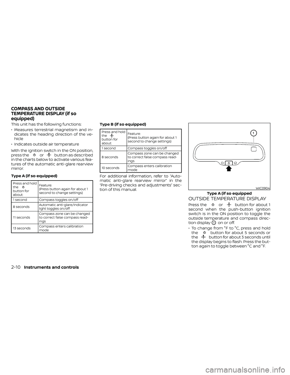
OUTSIDE TEMPERATURE DISPLAY
Press theorbutton for about 1
second when the push-button ignition
switch is in the ON position to toggle the
outside temperature and compass direc-
tion display
O1on or off.
• To change from °F to °C, press and hold the
button for about 5 seconds or
thebutton for about 3 seconds until
the display begins to flash. Press the but-
ton again to toggle between °C and °F.
WIC0904
Type A (if so equipped
COMPASS AND OUTSIDE
TEMPERATURE DISPLAY (if so
equipped)