2021 NISSAN ARMADA battery
[x] Cancel search: batteryPage 129 of 603

button for longer than 1 second.
The display is updated every 30 seconds.
At about the first 1/3 mile (500 m) after a
reset, the display shows “——”.
8. Intelligent Cruise Control (ICC)
system
This mode shows the operating condition
for the Intelligent Cruise Control (ICC)
system. (See “Intelligent Cruise Control
(ICC)” (P.5-74).)
NOTE:
If the ICC system is in a standby state,
this screen is automatically displayed.
9. Driving aids (if so equipped)
The driving aids mode shows the operat-
ing condition for the following systems, if
the vehicle is equipped with them.
. Automatic Emergency Braking (AEB)
with pedestrian detection system
. Intelligent Forward Collision Warning
(I-FCW)
. Lane Departure Warning (LDW)
. Intelligent Lane Intervention (I-LI)
. Blind Spot Warning (BSW)
. Intelligent Blind Spot Intervention (I-
BSI)
For more details, see “Automatic Emer-
gency Braking (AEB) with pedestrian de-
tection system” (P.5-96), “Intelligent Forward Collision Warning (I-FCW)” (P.5-
106), “Lane Departure Warning (LDW)” (P.5-
26), “Intelligent Lane Intervention (I-LI)”
(P.5-31), “Blind Spot Warning (BSW)” (P.5-
38) or “Intelligent Blind Spot Intervention
(I-BSI)” (P.5-46).
10. Tire pressures
The tire pressure mode shows the pres-
sure of all four tires while the vehicle is
driven.
When the “Tire Pressure Low Add Air”
warning appears, the display can be
switched to the tire pressure mode by
pushing the left or right side of the
button.
The tire pressure unit can be changed
using the “TPMS Setting” menu displayed
in the vehicle information display. (See
“TPMS Setting” (P.2-22).)
NOTE:
After the ignition switch is placed in the
ON position, it may take a period of time
for the tire pressure to be displayed
while the vehicle is driven. Depending
on the radio wave circumstance, tire
pressure may not correctly be dis-
played.WAC0225X
11. Auxiliary gauges
The auxiliary gauges consist of the bat-
tery voltage gauge and the engine oil
pressure gauge.
The engine oil pressure gauge indicates
current engine oil pressure. (See “Engine
oil pressure gauge” (P.2-8).)
The battery voltage gauge indicates cur-
rent battery voltage. (See “Voltmeter” (P.2-
9).)
Instruments and controls2-37
Page 137 of 603

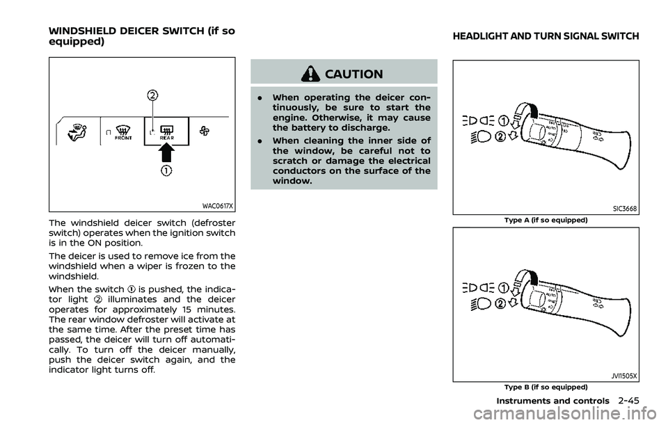
WAC0617X
The windshield deicer switch (defroster
switch) operates when the ignition switch
is in the ON position.
The deicer is used to remove ice from the
windshield when a wiper is frozen to the
windshield.
When the switch
is pushed, the indica-
tor lightilluminates and the deicer
operates for approximately 15 minutes.
The rear window defroster will activate at
the same time. After the preset time has
passed, the deicer will turn off automati-
cally. To turn off the deicer manually,
push the deicer switch again, and the
indicator light turns off.
CAUTION
. When operating the deicer con-
tinuously, be sure to start the
engine. Otherwise, it may cause
the battery to discharge.
. When cleaning the inner side of
the window, be careful not to
scratch or damage the electrical
conductors on the surface of the
window.
SIC3668
Type A (if so equipped)
JVI1505XType B (if so equipped)
Instruments and controls2-45
WINDSHIELD DEICER SWITCH (if so
equipped)HEADLIGHT AND TURN SIGNAL SWITCH
Page 141 of 603

To turn off the high beam assist system,
turn the headlight switch to the
position or select the low beam position
by placing the lever in the neutral posi-
tion.
WAC0618X
Ambient image sensor maintenance:
The ambient image sensor
for the high
beam assist system is located as shown.
To keep the proper operation of the high
beam assist system and prevent a system
malfunction, be sure to observe the
following:
. Always keep the windshield clean.
. Do not attach a sticker (including
transparent material) or install an
accessory near the ambient image
sensor.
. Do not strike or damage the areas
around the ambient image sensor. Do
not touch the sensor lens that is
located on the ambient image sensor. If the ambient image sensor is damaged
due to an accident, contact a NISSAN
dealer.
Battery saver system
A chime will sound when the driver side
door is opened with the light switch in the
orposition and the ignition
switch in the OFF or LOCK position.
When the headlight switch is in the
orposition while the ignition switch is in
the ON position, the lights will automati-
cally turn off after a period of time when
the ignition switch has been pushed to
the OFF position.
When the headlight switch remains in the
orposition after the lights auto-
matically turn off, the lights will turn on
when the ignition switch is pushed to the
ON position.
CAUTION
. When you turn on the headlight
switch again after the lights auto-
matically turn off, the lights will
not turn off automatically. Be
sure to turn the light switch to
the OFF position when you leave
the vehicle for extended periods
of time, otherwise the battery will
Instruments and controls2-49
Page 145 of 603

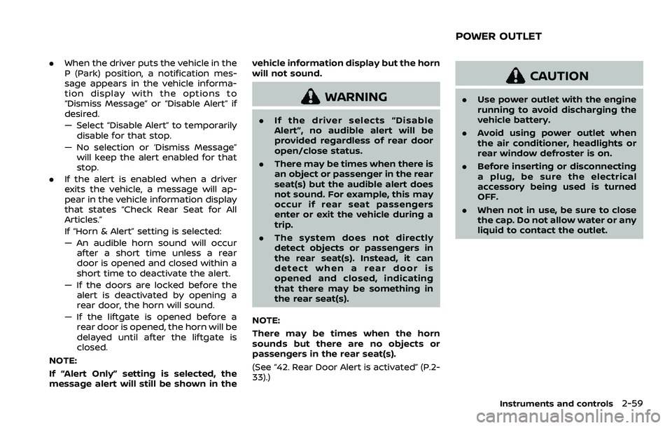
SIC4444
To sound the horn, push the center pad
area of the steering wheel.
WARNING
Do not disassemble the horn. Doing
so could affect proper operation of
the supplemental front air bag sys-
tem. Tampering with the supple-
mental front air bag system may
result in serious personal injury.
WARNING
Do not use or allow occupants to use
the seat heater if you or the occu-
pants cannot monitor elevated seat
temperatures or have an inability to
feel pain in body parts that contact
the seat. Use of the seat heater by
such people could result in serious
injury.
CAUTION
.The battery could run down if the
seat heater is operated while the
engine is not running.
. Do not use the seat heater for
extended periods or when no one
is using the seat.
. Do not put anything on the seat
which insulates heat, such as a
blanket, cushion, seat cover, etc.
Otherwise, the seat may become
overheated.
. Do not place anything hard or
heavy on the seat or pierce it with
a pin or similar object. This may
result in damage to the heater. .
Any liquid spilled on the heated
seat should be removed immedi-
ately with a dry cloth.
. When cleaning the seat, never use
gasoline, thinner, or any similar
materials.
. If any malfunctions are found or
the heated seat does not operate,
turn the switch off and have the
system checked. It is recom-
mended you visit a NISSAN dealer
for this service.
Instruments and controls2-53
HORN HEATED SEATS
Page 147 of 603

3. To turn off the heater, return theswitch to the level position. Make sure
the indicator light turns off.
The heater is controlled by a thermo-
stat, automatically turning the heater
on and off. The indicator light will
remain on as long as the switch is on.
When the vehicle’s interior is warmed,
or before you leave the vehicle, be
sure to turn off the switch.
WAC0640X
The climate controlled seat cools down
the front seats by blowing cool air from
the surface of the seat. The switches
located on the instrument panel can be
operated independently of each other.
1. Start the engine.
2. Push the climate controlled seatswitch to cool the seat. The indicator
light
on the corresponding switch
will illuminate depending on the cool
level.
3. Adjust the desired amount of air by pushing the switch again. The climate
controlled seat blower remains on low
speed for approximately 60 seconds
after pushing the switch on. 4. When the vehicle’s interior is warmed
or cooled, or before you leave the
vehicle, be sure to turn off the climate
controlled seats. To turn off the cli-
mate controlled seats, push the
switch until the indicator light turns
off.
To check the air filters for the climate
controlled seat, it is recommended
you visit a NISSAN dealer.
WARNING
Do not use or allow occupants to use
the climate controlled seats if you or
the occupants cannot monitor seat
temperatures or have an inability to
feel pain in those body parts in
contact with the seat. Use of the
climate controlled seats by such
people could result in serious injury.
CAUTION
.The battery could run down if the
climate controlled seat is oper-
ated while the engine is not run-
ning.
Instruments and controls2-55
CLIMATE CONTROLLED SEATS (if
so equipped)
Page 151 of 603

.When the driver puts the vehicle in the
P (Park) position, a notification mes-
sage appears in the vehicle informa-
tion display with the options to
“Dismiss Message” or “Disable Alert” if
desired.
— Select “Disable Alert” to temporarily
disable for that stop.
— No selection or ‘Dismiss Message” will keep the alert enabled for that
stop.
. If the alert is enabled when a driver
exits the vehicle, a message will ap-
pear in the vehicle information display
that states “Check Rear Seat for All
Articles.”
If “Horn & Alert” setting is selected:
— An audible horn sound will occur
after a short time unless a rear
door is opened and closed within a
short time to deactivate the alert.
— If the doors are locked before the alert is deactivated by opening a
rear door, the horn will sound.
— If the liftgate is opened before a rear door is opened, the horn will be
delayed until after the liftgate is
closed.
NOTE:
If “Alert Only” setting is selected, the
message alert will still be shown in the vehicle information display but the horn
will not sound.
WARNING
.
If the driver selects “Disable
Alert”, no audible alert will be
provided regardless of rear door
open/close status.
. There may be times when there is
an object or passenger in the rear
seat(s) but the audible alert does
not sound. For example, this may
occur if rear seat passengers
enter or exit the vehicle during a
trip.
. The system does not directly
detect objects or passengers in
the rear seat(s). Instead, it can
detect when a rear door is
opened and closed, indicating
that there may be something in
the rear seat(s).
NOTE:
There may be times when the horn
sounds but there are no objects or
passengers in the rear seat(s).
(See “42. Rear Door Alert is activated” (P.2-
33).)
CAUTION
. Use power outlet with the engine
running to avoid discharging the
vehicle battery.
. Avoid using power outlet when
the air conditioner, headlights or
rear window defroster is on.
. Before inserting or disconnecting
a plug, be sure the electrical
accessory being used is turned
OFF.
. When not in use, be sure to close
the cap. Do not allow water or any
liquid to contact the outlet.
Instruments and controls2-59
POWER OUTLET
Page 153 of 603

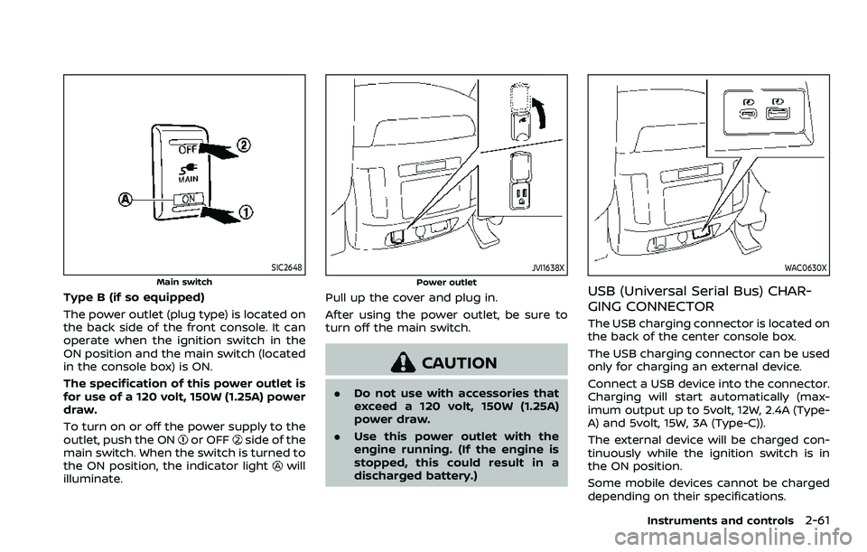
SIC2648
Main switch
Type B (if so equipped)
The power outlet (plug type) is located on
the back side of the front console. It can
operate when the ignition switch in the
ON position and the main switch (located
in the console box) is ON.
The specification of this power outlet is
for use of a 120 volt, 150W (1.25A) power
draw.
To turn on or off the power supply to the
outlet, push the ON
or OFFside of the
main switch. When the switch is turned to
the ON position, the indicator light
will
illuminate.
JVI1638X
Power outlet
Pull up the cover and plug in.
After using the power outlet, be sure to
turn off the main switch.
CAUTION
. Do not use with accessories that
exceed a 120 volt, 150W (1.25A)
power draw.
. Use this power outlet with the
engine running. (If the engine is
stopped, this could result in a
discharged battery.)
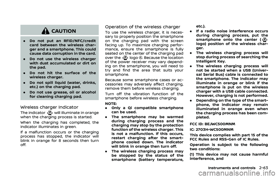
WAC0630X
USB (Universal Serial Bus) CHAR-
GING CONNECTOR
The USB charging connector is located on
the back of the center console box.
The USB charging connector can be used
only for charging an external device.
Connect a USB device into the connector.
Charging will start automatically (max-
imum output up to 5volt, 12W, 2.4A (Type-
A) and 5volt, 15W, 3A (Type-C)).
The external device will be charged con-
tinuously while the ignition switch is in
the ON position.
Some mobile devices cannot be charged
depending on their specifications.
Instruments and controls2-61
Page 155 of 603

CAUTION
.Do not put an RFID/NFC/credit
card between the wireless char-
ger and a smartphone. This could
cause data corruption in the card.
. Do not use the wireless charger
with dust accumulated or dirt on
the pad.
. Do not hit the surface of the
wireless charger.
. Do not spill liquid (water, drinks,
etc.) on the charging pad.
. Do not use grease, oil or alcohol
for cleaning charging pad.
Wireless charger Indicator
The indicatorwill illuminate in orange
when the charging process is started.
When the charging has completed, the
indicator illuminates in green.
If a malfunction occurs or the charging
process has stopped, the indicator will
blink in orange for 8 seconds then turn
off.
Operation of the wireless charger
To use the wireless charger, it is neces-
sary to properly position the smartphone
on the charging pad with the screen
facing up. To maximize charging perfor-
mance, ensure the smartphone is fully
seated on the center of the charging pad
over the
logo. Because the location
of the power receiver may vary depend-
ing on the smartphone, you will need to
try and find the area that suits your
smartphone.
Because some smartphone cases or ac-
cessories may adversely affect charging,
remove them before wireless charging.
Turn off the vibration function of the
smartphone before wireless charging.
NOTE:
. Only a Qi compatible smartphone
can be used.
. The smartphone may be warmed
during charging process and the
charging may stop by the protection
function of the wireless charger. This
is not a malfunction. If this occurs,
restart charging after the smart-
phone cooled down. The indicator
will blink in orange then turn off.
. The wireless charging process may
be stopped by the status of the
smartphone (battery temperature, etc.).
. If a radio noise interference occurs
during charging process, put the
smartphone onto the center (
logo) position of the wireless char-
ger.
. The wireless charging process will
stop during process of searching the
Intelligent Key.
. The wireless charging process will
not be started when a USB (Univer-
sal Serial Bus) cable is connected to
the smartphone. The indicator may
illuminate in orange or blink if the
smartphone is put on the wireless
charger with a USB cable connected.
However, charging is not performed.
. Depending on the type of the smart-
phone, the indicator may remain
illuminated in orange even when
the charging process has been com-
pleted.
FCC ID: BEJWC500MNM
IC: 2703H-WC500MNM
This device complies with part 15 of the
FCC Rules and RSS-Gen of IC Rules.
Operation is subject to the following
two conditions:
(1) This device may not cause harmful
interference, and
Instruments and controls2-63