2021 MERCEDES-BENZ GLE COUPE ignition
[x] Cancel search: ignitionPage 326 of 525
Fo
r accident clarification purposes, thefo llowing
measures can be take n up toan hour af terthe
emer gency call has been initia ted:
R The cur rent vehicle position can be de ter‐
mined.
R Avo ice connection totheve hicle occupants
can be es tablished.
R Emer gency call da tacan be called up.
% ForRu ssia: various functions, e.g. receiving
traf fic information, cannot be per form ed for
up totwo hou rsafte r sending an emer gency
call. Self diagnosis function of the eme
rgency call
sy stem Yo
ur car verifies the operability of the emer‐
ge ncy call sy stem each time the ignition is ON.
In case of sy stem failure, you will be informed
with text messa geon the instrument clus ter and
with red indicator SOS NOT READY onthe dis‐
pla y.
Please, make sure, that during 30 seconds af ter
switching ignition ON there d indicator SOS NOT READY
inthe upper right corner of display
is switched OFF, this means the emer gency call
sy stem passed diagnostics successfully. St
arting/ending ERA-GLONASS test mode Re
quirements:
R The star ter battery is suf ficiently charge d.
R The ignition is switched on.
R The vehicle has been stationary for at least
one minute.
% The test mode is cur rently available in the
fo llowing countries, forex ample:
R Russia
R Belarus
R Kazakh stan
R Armenia
R Kyrgyzs tan #
Tostart thete st mode: press and hold the
0076 button on the multifunction steering
wheel for at least five seconds.
The test mode is star ted and automatically
ends af terth e language test has been per‐
fo rm ed. #
Toend thete st mode manuall y:switch off
th e ignition.
The test mode is ended. Information on data processing
Processing of personal data via
the
Mercedes-Benz emer gency call sy stem
All processing of personal data via the
Mercedes-Benz emer gency call sy stem cor re‐
sponds with the specifications in the EU Regula‐
tion 20 16/679 "on the pr otection of individuals
with rega rd tothe processing of personal data
(GDPR)".
The data is solely used bythe Mercedes-Benz
emer gency call sy stem forre scue and reco very
in theeve nt of an accident. MBUX multimedia sy
stem 323
Page 338 of 525
&
WARNING Risk of injury duetomoving
parts
Components in the engine compartment may
continue running or start up sudden ly,even if
th e ignition is switched off.
Make sure of thefo llowing before per form ing
ta sks in the engine compartmen t:#
Switch the ignition off. #
Neverre ach into the danger zone sur‐
ro unding moving co mponents, e.g. the
ro tation area of thefa n. #
Remo vejewe llery and watches. #
Keep items of clo thing and hair away
from moving parts. &
WARNING Risk of injury fromtouching
co mp onents under voltage
The ignition sy stem and the fuel injection
sy stem workunder high voltage. You could
re cei vean electric shoc k. #
Neverto uch co mponents of the ignition
sy stem or the fuel injection sy stem
when the ignition is switched on. The live components include
thefo llowing, for
ex ample:
R ignition coils
R fuel injectors
R electric lines tothe ignition coils or the fuel
injec tors &
WARNING Risk of burn s from hot com‐
ponent parts in the engine compartment
Cer tain component parts in the engine com‐
partment can be very hot, e.g. the engine,
th e cooler and parts of theex haust sy stem. #
Allow the engine tocool down and only
to uch co mponent parts described in
th efo llowing. &
WARNING Risk of injury from usingthe
windscreen wipers while the engine bon‐
net is open
When the engine bonn etis open, and the
windscreen wipers are set in motion, you can
be trapped bythe wiper linkage. #
Alw ays switch off the windscreen wip‐
ers and ignition before opening the
engine bonn et. *
NO
TEPlug-in hybrid #
Obser vethe no tes in the Supplement.
Yo u could otherwise failto recognise
dangers. Maintenance and care
335
Page 340 of 525
On-board computer:
4 Service 5
Engine oil level
One of thefo llowing messages will appear on
th e multifunction display:
R Engine oil level Measuring now : measure‐
ment of the oil le vel is not yet possible. #
Repeat there qu est af ter a maximum of
30 minutes' driving.
R Engine oil level OK andthe bar display for
indicating the oil le vel on the multifunction
display is green and is between "min" and
"max": the oil le vel is cor rect.
R Engine oil level Add 1,0 l andthe bar display
fo r indicating the oil le vel on the multifunc‐
tion display is orange and is below "min": #
Add 1 l of engine oil.
R Reduce engine oil level andthe bar display
fo r indicating the oil le vel on the multifunc‐
tion display is orange and is abo ve"max": #
Drain off any excess engine oil that has been
added. Todo so, consult a qualified specialist
wo rkshop.
R For engine oil level turn on ignition #
Switch on the ignition tocheck the engine oil
le ve l.
R Engine oil level System inoperative : The oil
le ve l sensor is defective or not connecte d. #
Consult a qualified specialist workshop.
R Engine oil level System currently unavail. #
Close the bonn et.
To pping up engine oil &
WARNING Risk of burn s from hot com‐
ponent parts in the engine compartment
Cer tain component parts in the engine com‐
partment can be very hot, e.g. the engine,
th e cooler and parts of theex haust sy stem. #
Allow the engine tocool down and only
to uch co mponent parts described in
th efo llowing. &
WARNING Risk offire and injury from
engine oil
If engine oil comes into con tact with hot
component parts in the engine compart‐
ment, it may ignite. #
Make sure that no engine oil is spilled
next tothefiller opening. #
Allow the engine tocool off and thor‐
oughly clean the engine oil from compo‐
nent parts before starting theve hicle. *
NO
TEEngine damage causedbyan
incor rect oil filter, incor rect oil or addi‐
tives #
Do not use engine oils or oil filters
which do not cor respond tothe specifi‐
cations explicitly prescribed forthe
service inter vals. #
Follow the instructions on the service
inter val display forch anging the engine
oil and obser vethe prescribed change
inter vals. Maintenance and care
337
Page 348 of 525
-
oily products
R Do not use polish on matt decorative foil.
Po lishing will ha vethe ef fect of shining the
fo il-wrapped sur face.
R Do not treat matt or stru ctured deco rative
fo ils with wax.Pe rm anent stains may occur.
Sc ratches, cor rosive deposits, areas af fected by
cor rosion and damage caused byincor rect care
cannot al ways be comple tely re paired. In such
cases, visit a qualified specialist workshop.
Yo u can obtain more information on care and
cleaning products from the manufacturer.
In the case of foil-wrapped sur faces, optical dif‐
fe re nces may occur between the sur faces that
we renot pr otected bya decorative foil af ter
re moving a decorative foil.
% Have wo rkor repairs todecorative foils car‐
ri ed out at a qualified specialist workshop,
e.g. in a Mercedes-Benz Service Centre. Note
s on care of car parts &
WARNING Risk of entrapment if the
windscreen wipers are swit ched on while
th e windscreen is being cleaned
If th e windscreen wipers are set in motion
while you are cleaning the windscreen or
wiper blades, you can be trapped bythe
wiper arm. #
Alw ays switch off the windscreen wip‐
ers and the ignition before cleaning the
windscreen or wiper blades. &
WARNING Risk of burn s fromtheta il‐
pipe and tailpipe trims
The exhaust tailpipe and tailpipe trims can
become very hot. If you come into contact
with these parts of theve hicle, you could
burn yourself. #
Alw ays be particular lycareful around
th eta ilpipe and theta ilpipe trims and
supervise children especially closely in
th is area. #
Allow vehicle parts tocool down before
to uching them. To
avo id damage totheve hicle, obser vethe
no tes on cleaning and care of thefo llowing vehi‐
cle parts:
Wheels and rims
R Use wate r and acid-free alloy wheel cleaners.
R Do not use acidic alloy wheel cleaners to
re mo vebrake dust. This could damage wheel
bolts and brake components.
R Toavo id cor rosion of the brake disks and
brakepads, drive theve hicle for a few
minutes af ter cleaning before parking it. The
brake disks and brakepads warm up and dry
out.
Wi ndo ws
R Clean the windo wsinside and outside with a
damp clo thand with a cleaning agent recom‐
mended for Mercedes-Benz.
R Do not use dry clo ths or abrasive or sol vent-
based cleaning agents toclean the inside of
windo ws. Maintenance and care
345
Page 358 of 525
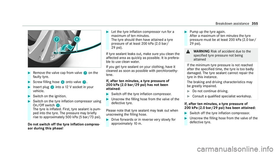
#
Remo vetheva lve cap from valve 7 onthe
fa ulty tyre. #
Screw filling hose 8onto valve 7. #
Insert plug 4into a 12V soc ket in your
ve hicle. #
Switch on the ignition. #
Switch on the tyre inflation compressor using
On/Off switch 3.
The tyre is inflated. Fir st, tyre sealant is pum‐
ped into the tyre. The pressure may brief ly
ri se toappr oximately 500 kPa (5 bar/73 psi).
Do not switch off the ty reinflation compres‐
sor during this phase! #
Let the tyre inflation compressor runfo r a
maximum of ten minu tes.
The tyre should then ha veattained a tyre
pressure of at least 200 kPa (2.0 bar/
29 psi).
If tyre sealant leaks out, make sure you clean the
af fected area as quickly as possible. It is prefera‐
ble touse clean water.
If yo uge t tyre sealant on your clo thing, ha veit
cleaned as soon as possible with per chloroe thy‐
lene.
If, af terte n minutes, a tyre pressure of
200 kPa (2.0 bar/29 psi) has not been
attained: #
Switch off the tyre inflation compressor. #
Unscr ew thefilling hose from theva lve of the
defective tyre.
Please no tethat tyre sealant may leak out when
unscr ewing thefilling hose. #
Drive forw ards or in reve rseve ry slowly for
appr oximately 10m. #
Pump up the tyre again.
Af ter a maximum of ten minu testh e tyre
pressure must be at least 200 kPa (2.0 bar/
29 psi). &
WARNING Risk of accident due tothe
specified tyre pressure not being
attained
If th e minimum tyre pressure is not reached
af te rth e specified time, the tyre is too badly
damaged. The tyre sealant cannot repair the
tyre in this ins tance.
The braking and driving characteristics may
be great lyimpaired. #
Do not continue driving. #
Consult a qualified specialist workshop. If, af
terte n minutes, a tyre pressure of
200 kPa (2.0 bar/29 psi) has been attained: #
Switch off the tyre inflation compressor. #
Unscr ew thefilling hose from theva lve of the
defective tyre. Breakdown assis
tance 355
Page 364 of 525
Obser
vethe additional following points during
st arting assistance:
R Starting assis tance may only be pr ovided
using vehicles, batteries or other jump start
devices with a nominal voltage of 12V.
R The vehicles must not touch.
R Vehicles with a petrol engine: jump-start
th eve hicle only when the engine and exhaust
sy stem are cold. St
arting assi stance and charging the12 V
battery Requ
irements:
R The vehicle is secured with the electric park‐
ing brake.
R Vehicles with automatic transmission: the
transmission is in position 005D.
R The ignition and all electrical consumers are
switched off.
R The bonnet is open. Example: engine compartment
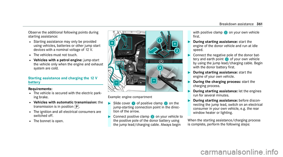
#
Slide co ver1 of positive clamp 2onthe
jump-s tarting connection point in the direc‐
tion of the ar row. #
Connect positive clamp 2onyour vehicle to
th e positive pole of the donor battery using
th e jump lead/charging cable. Alw ays begin with positive clamp
2onyour ow nve hicle
fi rs t. #
During starting assi stance: start the
engine of the donor vehicle and run at idle
speed. #
Connect the negative pole of the donor bat‐
te ry and ear thpoint 3ofyour ow nve hicle
by using the jump lead/charging cable. Begin
with the donor battery firs t. #
During starting assi stance: start the
engine of your ow nve hicle. #
During thech arging process: start the
ch arging process. #
During starting assi stance: letthe engines
ru nfo r se veral minutes. #
During starting assi stance: before discon‐
necting the jump lead, switch on an electrical
consumer in your ow nve hicle, e.g. there ar
wind owheater or lighting.
When thest arting assis tance/charging process
is compl ete, per form thefo llowing steps: Breakdown assis
tance 361
Page 367 of 525
*
NO
TEDama gedue to to wing away at
exc essively high speeds or over long dis‐
ta nces The driv
etra in could be damaged when tow‐
ing at excessively high speeds or over long
dis tances. #
Atowing speed of 50 km/h must not
be exc eeded. #
Atowing dis tance of 50 km must not be
exc eeded. &
WARNING Risk of accident when towing
a ve hicle which is too heavy
If th eve hicle being tow- star ted or towed
aw ay is heavier than the permissible gross
mass, thefo llowing situations can occur:
R theto wing eye may become de tach ed.
R the car/t railer combination may swer ve
or eve nove rturn. #
If ano ther vehicle is tow- star ted or
to we daw ay, its weight must not exceed th
e permissible gross mass of your own
ve hicle. #
Information on the permissible gross mass of
th eve hicle can be found on theve hicle iden‐
tification plate (/ page 391). #
Do not open the driver's door or front
passenger door as the automatic transmis‐
sion may otherwise shift toposition 005Dauto‐
maticall y. #
Fittheto wing eye (/ page 366). #
Fasten theto w bar.
* NO
TEDama gedue toincor rect connec‐
tion of theto w bar #
Onlyconnect theto w rope or tow bar to
th eto wing eyes. %
You can also attach theto w bar tothe trailer
hitch. #
Deactivate the automatic locking mechanism
(/ page 81). #
Do not activate the HOLD function. #
Deactivate tow- aw ay protection
(/ page 97). #
Deactivate Active Brake Assi st
( / page 227). #
Shift the automatic transmission toposition
005C(/ page182). #
Release the electric parking brake. &
WARNING Risk of accident due tolimi‐
te d saf ety-re lated functions during the
to wing process
Saf ety-re lated functions are limited or no lon‐
ge rav ailable in thefo llowing situations:
R the ignition is switched off.
R the brake sy stem or po werst eering sys‐
te m is malfunctioning.
R the energy supply or the on-board electri‐
cal sy stem is malfunctioning.
When your vehicle is then towe daw ay, signif‐
icantly more ef fort may be requ ired tosteer
and brake than is norm allyrequ ired. #
Use a tow bar. 364
Breakdown assis tance
Page 371 of 525
*
NO
TEDama geor malfunctions caused
by moisture Moisture may cause dama
getothe electrical
sy stem or cause it tomalfunction. #
When the fuse box is open, make sure
th at no moisture can enter the fuse
box. #
When closing the fuse box, make sure
th at the seal of the lid is positioned cor‐
re ctly on the fuse box. If
th e newly inser ted fuse also blo ws, ha vethe
cause traced and rectified at a qualified special‐
ist workshop.
Ensure thefo llowing before replacing a fuse:
R The vehicle is secured against rolling away.
R All electrical consumers are switched off.
R The ignition is switched off. The electrical fuses are located in
various fuse
bo xes:
R Fuse box in the engine compartment on the
left-hand side of theve hicle, when vie wed in
th e direction of tr avel (/ page 368)
R Fuse box on the driver's side of the cockpit
(/ page 369)
R Fuse box in the front passenger foot we ll
(/ page 369)
R Fuse box in the load compartment on the
ri ght-hand side of theve hicle, when vie wed
in the direction of tr avel (/ page 369) Opening and closing
the fuse box in the
engine compa rtment Requ
irement:
R You need a dry clo thand a sc rewdriver.
Obser vethe no tes on electrical fuses
(/ page 367). Opening &
WARNING Risk of injury from usingthe
windscreen wipers while the engine bon‐
net is open
When the engine bonn etis open, and the
windscreen wipers are set in motion, you can
be trapped bythe wiper linkage. #
Alw ays switch off the windscreen wip‐
ers and ignition before opening the
engine bonn et. 368
Breakdown assis tance