2021 MERCEDES-BENZ GLC SUV warning lights
[x] Cancel search: warning lightsPage 14 of 481
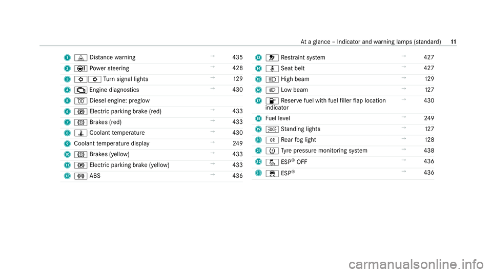
1
L Distance warning →
435
2 Ð Powe rst eering →
428
3 #! Turn signal lights →
12 9
4 ; Engine diagnostics →
430
5 % Diesel engine: preglow
6 ! Electric pa rking brake (red) →
433
7 J Brakes (red) →
433
8 ÿ Coolant temp erature →
430
9 Coolant temp erature display →
24 9
A J Brakes (yellow) →
433
B ! Electric parking brake (yell ow)→
433
C ! ABS →
436 D
6 Restra int sy stem →
427
E ü Seat belt →
427
F K High beam →
12 9
G L Low beam →
127
H 8 Reser vefuel with fuel filler flap location
indicator →
430
I Fuel le vel →
24 9
J T Standing lights →
127
K R Rear fog light →
12 8
L h Tyre pressure monitoring sy stem →
438
M å ESP®
OFF →
436
N ÷ ESP®
→
436 At
aglance – Indicator and warning lamps (s tanda rd) 11
Page 16 of 481
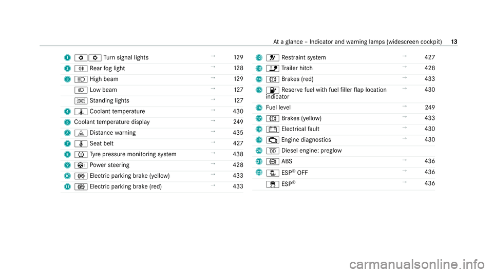
1
#! Turn signal lights →
12 9
2 R Rear fog light →
12 8
3 K High beam →
12 9
L Low beam →
127
T Standing lights →
127
4 ÿ Coolant temp erature →
430
5 Coolant temp erature display →
24 9
6 L Distance warning →
435
7 ü Seat belt →
427
8 h Tyre pressure monitoring sy stem →
438
9 Ù Powe rst eering →
428
A ! Electric pa rking brake (yellow) →
433
B ! Electric parking brake (red) →
433 C
6 Restra int sy stem →
427
D ï Trailer hit ch →
428
E J Brakes (red) →
433
F 8 Reser vefuel with fuel filler flap location
indicator →
430
G Fuel le vel →
24 9
H J Brakes (yellow) →
433
I # Electrical fault →
430
J ; Engine diagnostics →
430
K % Diesel engine: preglow
L ! ABS →
436
M å ESP®
OFF →
436
÷ ESP®
→
436 At
aglance – Indicator and warning lamps (widesc reen cockpit) 13
Page 42 of 481

te
m wa rning lamp lights up. It goes out no later
th an a few seconds af terth eve hicle is star ted.
The components of there stra int sy stem are then
functional. Malfunctioning
restra int sy stem A malfunction has occur
red in there stra int sys‐
te m if:
R the6 restra int sy stem warning lamp does
not light up when the ignition is switched on
R the6 restra int sy stem warning lamp
lights up continuously or repeatedly during a
journey &
WARNING Risk of injury duetomalfunc‐
tions in there stra int sy stem
Components in there stra int sy stem may be
activated unintentionally or not deploy as
intended in an accident. #
Have there stra int sy stem checked and
re paired immediately at a qualified spe‐
cialist workshop. Fu
nction of there stra int sy stem in an acci‐
dent How
there stra int sy stem works is de term ined by
th e se verity of the impact de tected and the type
of accident anticipated:
R Frontal impact
R Rear impact
R Side impact
R Rollover
The activation thre sholds forth e components of
th ere stra int sy stem are de term ined based on
th eev aluation of the sensor values measured at
va rious points in theve hicle. This process is pre-
em ptive in nature. The triggering/deployment of
th e components of there stra int sy stem must
ta ke place in good time at thest art of the colli‐
sion.
Fa ctors whi chcan only be seen and measu red
af te r a collision has occur red do not play a deci‐
sive role in the deployment of an airbag. Nordo
th ey prov ide an indication of airbag deployment.
The vehicle may be deformed significantly with‐
out an airbag being deplo yed. This is the case if only parts which are
relatively easily deformed
are af fected and thera te ofvehicle deceleration
is not high. Con versely, an airbag may be
deplo yedev en though theve hicle suf fers only
minor deformation. If very rigid vehicle parts
such as longitudinal members are hit, this may
re sult in suf ficiently high le vels of vehicle decel‐
eration.
Depending on the de tected deployment situa‐
tion, the components of there stra int sy stem can
be activated or deplo yed independently of each
ot her:
R Front seat belt tensioner: frontal impact, rear
impact, side impact, rollo ver
R Rear seat belt tensioner: frontal impact, rear
impact, rollo ver
R Driver's airbag, front passenger airbag: fron‐
tal impact
R Knee airbag: frontal impact
R Side airbag: side impact
R Window airbag: side impact, rollo ver,frontal
impact Occupant saf
ety39
Page 56 of 481
Yo
u will need toper form certain settings your‐
self. #
Ifth e seat belt pre-tensioning is not reduced,
mo vethe seat backrest back slightl y.
The locking mechanism releases. Fu
nction of PRE-SAFE ®
PLUS (anticipatory
occupant pr otection plus) PRE-
SAFE®
PLUS can de tect cer tain impacts,
particular lyan imminent rear impact, and take
pre-em ptive measures toprotect theve hicle
occupants. These measures cannot necessarily
pr eve nt an imminent impact.
PRE-SAFE ®
PLUS can implement thefo llowing
measures independently of each other:
R Tightening the seat belts on the driver's seat
and front passenger seat.
R Activating there ar hazard warning lights at a
higher flashing frequenc y.
R Increasing brake pressure when theve hicle
is stationar y.This brake application is cancel‐
led automatically when theve hicle pulls
aw ay. If an accident did not occur,
the pre-em ptive
measures that we retake n are reve rsed.
Sy stem limits
The sy stem will not initiate any action in thefo l‐
lowing situations:
R when reve rsing
or
R when theve hicle is towing a trailer and there
is a risk of a rear impact
The sy stem will not initiate any braking applica‐
tion in thefo llowing situations:
R whilst driving
or
R when entering or exiting a parking space
while using Active Parking Assist Safely transporting
children in theve hicle Alw
ays obser vewhen children are tr avelling
in theve hicle %
Also strictly obser vethe saf ety no tesfo rthe
specific situation. In this wa yyo u can recog‐ nise po
tential risks and avoid dangers if chil‐
dren are tr avelling in theve hicle
(/ page 54).
Be diligent
Bear in mind that negligence when securing a
ch ild in thech ild restra int sy stem may ha veseri‐
ous consequences. Alw ays be diligent in secur‐
ing a child carefully before everyjou rney.
To impr oveprotection forch ildren younger than
12 years old or under 1.50 m in height,
Mercedes-Benz recommends you obse rvethe
fo llowing information:
R Alw ays secure thech ild in a child restra int
sy stem suitable forth is Mercedes-Benz vehi‐
cle.
R The child restra int sy stem must be appropri‐
ate tothe age, weight and size of thech ild.
R The vehicle seat must be suitable forfitting a
ch ild restra int sy stem (/ page 58).
Ac cident statistics show that children secured
on there ar seats are general lysafer than chil‐
dren secured on the front seats. Forth is reason, Occupant saf
ety53
Page 126 of 481
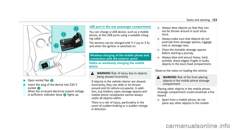
#
Open soc ketflap 3. #
Insert the plug of the device into 230 V
soc ket1.
When the on-board electrical sy stem voltage
is suf ficient, indicator la mp2lights up. USB port in
there ar passenger comp artment Yo
u can charge a USB device, such as a mobile
phone, at the USB ports using a suitable charg‐
ing cable.
The devices can be charge d with 5 V (up to3 A)
and when the ignition is switched on. Wire
lesscharging of the mobile phone and
connection with theex terior aerial Note
s on wirelessly charging the mobile
phone &
WARNING Risk of injury duetoobjects
being stowed incor rectly
If objects in theve hicle interior are stowed
incor rectly, they can slide or be thrown
around and hit vehicle occupants. In addi‐
tion, cup holders, open stowage spaces and
mobile phone recep tacles cannot al ways
re tain all objects within.
There is a risk of injur y,particularly in the
ev ent of sudden braking or a sudden change
in direction. #
Alw aysstow objects so that they can‐
not be throw n around in su chsitua‐
tions. #
Alw ays make sure that objects do not
pr otru de from stowage spaces, luggage
nets or stowage nets. #
Close the loc kable stow age spaces
before starting a journe y. #
Alw aysstow and secure heavy, hard,
poin ted, sharp-edged, fragile or bulky
objects in the boot/load compartment. Obser
vethe no tes on loading theve hicle. &
WARNING Risk offire from placing
objects in the mobile phone stowage
compartment
Placing other objects in the mobile phone
stow age compartment could con stitute a fire
hazard. #
Apart from a mobile phone, do not
place any other objects in the mobile Seats and
stowing 12 3
Page 131 of 481

5
L Low beam/high beam
6 R Switches there ar fog light on/off
When low beam is activated, theT indicator
lamp forth est anding lights will be deactivated
and replaced bytheL low- beam indicator
lamp. #
Alw ays park your vehicle safely using suf fi‐
cient lighting, in acco rdance with there le‐
va nt le galst ipulations.
* NO
TEBattery discharging byoperating
th est anding lights Operating
thest anding lights over a period of
hours puts a stra in on the batter y. #
Where possible, switch on the
ri ght X or left Wparking light. Fo
rve hicles that are wider than two metres or
lon gerth an six metres, sin gle-sided parking
lighting is not permitted in some count ries. In
th is case, thest anding lights are also swit ched
on in the parking lights position. If
th e battery is insuf ficiently charge d, thest and‐
ing lights or parking lights will be swit ched off
automatically tofacilitate the next engine start.
The exterior lighting (e xcept standing and park‐
ing lights) will swit choff automatically when the
driver's door is opened.
R Obser vethe no tes on sur round lighting
(/ page 135).
Au tomatic driving lights function
The standing lights, low beam and daytime run‐
ning lights are switched on au tomatically
depending on the ignition status and the light
conditions. &
WARNING Risk of accident when the
dipped beam is switched off in poor visi‐
bility
When the light switch is set toà ,the
dipped beam may not be switched on auto‐
matically if there is fog, snow or other causes
of poor visibility such as spr ay. #
In such cases, turn the light switch to
L . The automatic driving lights are only an aid.
Yo u
are responsible forve hicle lighting.
Switching there ar fog lights on or off
Re quirements:
R The light switch is in theL orà posi‐
tion. #
Press the R button.
Please obser vethe count ry-specific la wsonthe
use of rear fog lamps. 12 8
Light and sight
Page 132 of 481
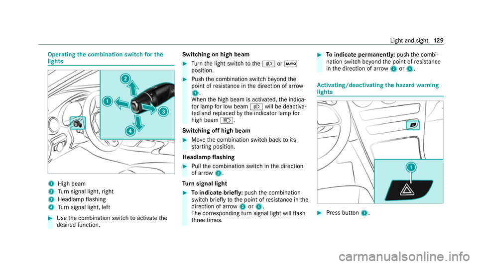
Operating
the combination switch for the
lights 1
High beam
2 Turn signal light, right
3 Headlamp flashing
4 Turn signal light, left #
Use the combination switch toactivate the
desired function. Switching on high beam #
Turn the light switch totheL orÃ
position. #
Push the combination switch be yond the
point of resis tance in the direction of ar row
1 .
When the high beam is activated, the indica‐
to r lamp for low beam Lwill be deactiva‐
te d and replaced bythe indicator lamp for
high beam K.
Switching off high beam #
Movethe combination switch back toits
st arting position.
Headla mpflashing #
Pull the combination switch in the direction
of ar row3.
Tu rn signal light #
Toindicate briefl y:push the combination
switch briefly tothe point of resis tance in the
direction of ar row2or4.
The cor responding turn signal light will flash
th re e times. #
Toindicate permanentl y:push the combi‐
nation switch be yond the point of resis tance
in the direction of ar row2or4. Ac
tivating/deactivating the hazard warning
lights #
Press button 1. Light and sight
12 9
Page 133 of 481
The hazard
warning lights will switch on auto‐
matically if:
R the airbag has been deplo yed.
R theve hicle is heavily braked from a speed of
more than 70 km/h toast andstill.
When you pull away again, the hazard warning
light sy stem will switch off automatically at
appr oximately 10km/h. You can also swit choff
th e hazard warning light sy stem using but‐
to n1. Ad
aptive functions, MULTIBEAM LED Intelligent Light Sy
stem function
The MULTIBEAM LED headlamps adapt tothe
driving and weather situation and pr ovide exten‐
ded functions for impr oved illumination of the
ro ad.
The sy stem comprises thefo llowing functions:
R Active headla mps (/ page130)
R Cornering light (/ page130)
R Motorw ay mode (/ page131)
R Enhanced fog light function (/ page131) The sy
stem is active only when it is dar k.
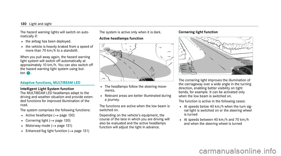
Ac tive headlamps function R
The headlamps follow thesteering mo ve‐
ments.
R Releva nt areas are better illumina ted during
a journe y.
The functions are active when the low beam is
switched on.
Depending on theve hicle's equipment, the
cou rse of the lane in which you are driving will
also be evaluated and the active headlamps
function will adjust the light in advance. Cornering light function
The cornering light impr
ovesth e illumination of
th e car riag ewa yove r a wide angle in the turning
direction, enabling better visibility on tight
bends, forex ample. It can be activated only
when the low beam is switched on.
The function is active in thefo llowing cases:
R Atspeeds below 40 km/h when the turn sig‐
nal light is switched on or thesteering wheel
is turned
R Atspeeds between 40 km/h and 70 km/h
and when thesteering wheel is turned 13 0
Light and sight