2021 MERCEDES-BENZ GLC COUPE fuel
[x] Cancel search: fuelPage 179 of 481
Ad
Blue ®
displ ayed. Switch on the ignition
and waitfor appro ximately 60 seconds. Start
th e engine.
Yo u can see theAd Blue ®
ra nge and le vel in the
Service menu in the multifunction displa y.
% The AdBlue ®
ra nge shown depends strongly
on the driving style and operating condi‐
tions. The actual range can therefore deviate
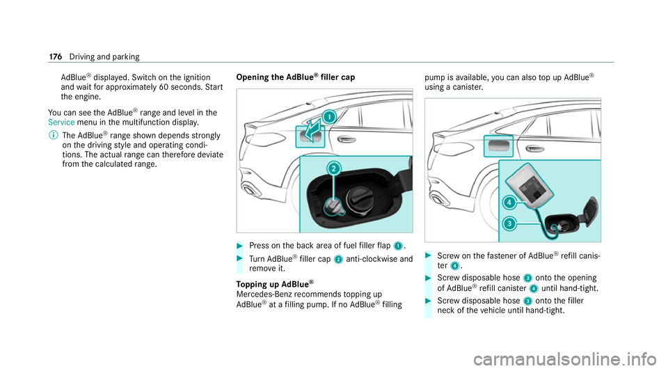
from the calculated range. Opening the
AdBlue ®
filler cap #
Press on the back area of fuel filler flap 1. #
Turn AdBlue ®
filler cap 2anti-clockwise and
re mo veit.
To pping up AdBlue ®
Mercedes-Benz recommends topping up
Ad Blue ®
at a filling pump. If no AdBlue ®
filling pump is
available, you can also top up AdBlue ®
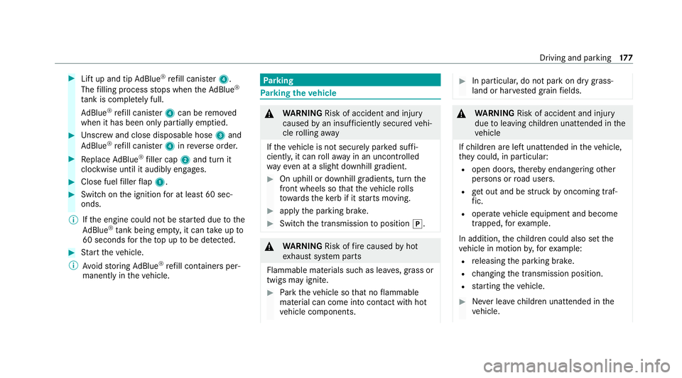
using a cani ster. #
Screw onthefast ener of AdBlue ®
re fill canis‐
te r4. #
Screw disposable hose 3onto the opening
of Ad Blue ®
re fill canis ter4 until hand-tight. #
Screw disposable hose 3onto thefiller
neck of theve hicle until hand-tight. 176
Driving and pa rking
Page 180 of 481
#
Lift up and tip AdBlue ®
re fill canis ter4.
The filling process stops when theAd Blue ®
ta nk is compl etely full.
Ad Blue ®
re fill canis ter4 can be remo ved
when it has been only partially em ptied. #
Unscr ew and close disposable hose 3and
Ad Blue ®
re fill canis ter4 inreve rse order. #
Replace AdBlue ®
filler cap 2and turn it
clockwise until it audibly engages. #
Close fuel filler flap 1. #
Swit chon the ignition for at least 60 sec‐
onds.
% Ifth e engine could not be star ted due tothe
Ad Blue ®
tan k being empty, it can take up to
60 seconds forth eto p up tobe de tected. #
Start theve hicle.
% Avoid storing AdBlue ®
re fill conta iners per‐
manently in theve hicle. Pa
rking Pa
rking theve hicle &
WARNING Risk of accident and inju ry
caused byan insuf ficiently secu redve hi‐
cle rolling away
If th eve hicle is not securely par ked suf fi‐
ciently, it can rollaw ay in an uncontro lled
wa yev en at a slight downhill gradient. #
On uphill or downhill gradients, turn the
front wheels so that theve hicle rolls
to wa rdsth eke rb if it starts moving. #
apply the parking brake. #
Switch the transmission toposition j. &
WARNING Risk offire caused byhot
ex haust sy stem parts
Flammable materials such as lea ves, grass or
twigs may ignite. #
Park theve hicle so that no flammable
material can come into con tact with hot
ve hicle components. #
In particular, do not park on dry grass‐
land or har vested grain fields. &
WARNING Risk of accident and inju ry
due toleaving children unat tended in the
ve hicle
If ch ildren are left unat tended in theve hicle,
th ey could, in part icular:
R open doors, thereby endangering other
persons or road users.
R get out and be stru ck byoncoming traf‐
fi c.
R ope rate ve hicle equipment and become
trapped, forex ample.
In addition, thech ildren could also set the
ve hicle in motion by,fo rex ample:
R releasing the parking brake.
R changing the transmission position.
R starting theve hicle. #
Never lea vechildren unat tended in the
ve hicle. Driving and parking
17 7
Page 199 of 481
Deactivating cruise cont
rol or theva riable
limi ter #
Select Owith th e left rock er switch.
% Ifyo u brake, deactivate ESP ®
or if ESP ®
inter venes, cruise control is deacti vated. The
va riable limiter is not deactivated.
Information on the permanent limiter
If th eve hicle should ne verexc eed a specific
speed (e.g. for driving in winter tyre mode), you
can set this speed with the permanent limiter.
Yo u do this by limiting the speed between
16 0 km/h and 240 km/h in the multimedia sys‐
te m (/ page196).
Shortly before the set speed is reached, it
appears in the multifunction displa y.When you
confirm the message, display messages no lon‐
ge r appear until you swit choff theve hicle. The
speed will only be displa yed again once theve hi‐
cle has been restar ted or if the set speed is
ch anged.
The permanent limiter does not swit chtopas‐
sive mode even du ring kickdown and the driven
speed remains below the set speed. Setting
the speed limitation for winter tyres
Multimedia sy stem:
4 © 5
Settings 5
Vehicle
5 Winter tyres limit #
Select a speed or deactivate the function. Ac
tive Di stance Assist DISTRO NIC Fu
nction of Active Di stance Assist
DISTRO NIC
Ac tive Dis tance Assi stDISTRONIC maintains the
set speed on free-flowing roads. If vehicles in
front are de tected, the set dis tance is main‐
ta ined, if necessar y,until theve hicle comes to a
halt. The vehicle accelerates or brakes depend‐
ing on the dis tance totheve hicle in front and
th e set speed. The speed and dis tance tothe
ve hicle in front are set and sa ved using the
st eering wheel.
Av ailable speed range:
R Vehicles without Driving Assistance Pack‐
age: 20 km/h - 200 km/h
R Vehicles with Driving Assistance Pack‐
age: 20 km/h - 210 km/h %
Plug-in hybrid: the adjus table set speed can
be reduced due tothe selected drive pro‐
gram. Obser vethere leva nt no tes in the Sup‐
plement.
Other features of Active Dis tance Assi st
DISTRONIC:
R Adjusts the driving style depending on the
selected drive program (fuel-saving, comfort‐
able or dynamic)
R Initiates acceleration tothestored speed if
th e turn signal indicator is switched on to
ch ange totheove rtaking lane
R Vehicles with Driving Assistance Pack‐
age:
- Reacts tostationary vehicles de tected in
urban speed ranges (e xcept bicycles and
mo torcyc les)
- Take s one-sided overtaking restrictions
into account on mo torw ays or on multi-
lane roads with separate car riag ew ays
(countr y-dependent)
Ve hicles with Driving Assistance Package
and Park ingPackage: ifth eve hicle has been 19 6
Driving and pa rking
Page 221 of 481
AIR BODY
CONTROL is an air suspension sy stem
with variable damping for impr oved driving com‐
fo rt. The all-round le vel control sy stem ensures
th e best possible suspension and const ant
ground clearance, even wi tha laden vehicle.
When driving at speed, theve hicle is lo wered
automatically toimpr ovedriving saf ety and to
re duce fuel consum ption. You also ha vethe
option of manually adjusting theve hicle le vel.
AIR BODY CONTROL includes thefo llowing com‐
ponents and functions:
R air suspension with variable spring rate
R automatic le vel control sy stem
R speed-dependent lo wering toreduce fuel
consum ption
R manually selec table high-le vel setting for
grea ter ground clea rance
R ADS PLUS (Ada ptive Damping Sy stem with
const ant damping forc e adjustment)
R DYNA MIC SELECT switch and le vel button Suspension setting and
vehicle le vel per
drive prog ram
Drive prog ram A:
R The suspension setting is comfor table.
R The vehicle is set tothe normal le vel.
R When driving at speeds abo veappr oximately
13 8 km/h, theve hicle is lo wered.
R When driving at speeds below appr oximately
80 km/h, theve hicle is raised again.
Drive prog ram ;:
R The suspension setting is comfor table.
R The vehicle is set tolow le vel -1.
R The vehicle is not lo wered any fur ther if you
are tr avelling at higher speeds.
Drive prog ram C:
R The suspension setting is firm er.
R The vehicle is set tolow le vel -1.
R The vehicle is not lo wered any fur ther if you
are tra velling at higher speeds. Drive prog
ram B:
R The suspension setting is evenfirm er.
R The vehicle is set tolow le vel -1.
R The vehicle is not lo wered any fur ther if you
are tra velling at higher speeds.
Individual suspension settings can be called up
in drive progra m= (/page 165).
% Operation with a trailer or bicyclerack:if
transpo rtequipment, such as a trailer or a
bicycle rack , is attached tothe trailer hitch
and the electrical connection has been cor‐
re ctly es tablished, theve hicle remains at
normal le vel ir respective of speed.
Dif fere nces between diff erentvehicle le vels
compared tothe normal le vel (0):
R High le vel +1: approximately +15 mm (Bra‐
zil: appr oximately +30 mm)
R Low le vel -1: approximately -15 mm 218
Driving and pa rking
Page 252 of 481
Instrument display
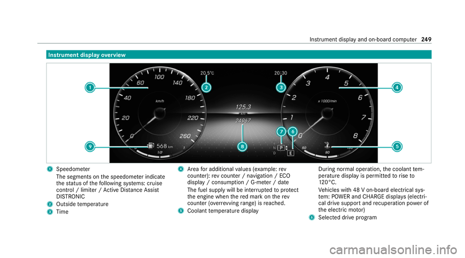
overview 1
Speedome ter
The segments on the speedome ter indica te
th est atus of thefo llowing sy stems: cruise
control / limiter / Active Dis tance Assi st
DISTRONIC
2 Outside temp erature
3 Time 4
Area for additional values (e xamp le:rev
counter): rev counter / navigation / ECO
display / consum ption / G-me ter / date
The fuel supply will be inter rupted toprotect
th e engine when there d mark on therev
counter (o verrev ving range) is reached.
5 Coolant temp erature display During normal operation,
the coolant tem‐
perature display is permitted torise to
12 0°C.
Ve hicles with 48 V on-board electrical sys‐
te m: POWER and CHARGE displ ays (electri‐
cal drive support and recuperation po wer of
th e electric mo tor)
6 Selected drive program Instrument display and on-board computer
249
Page 253 of 481
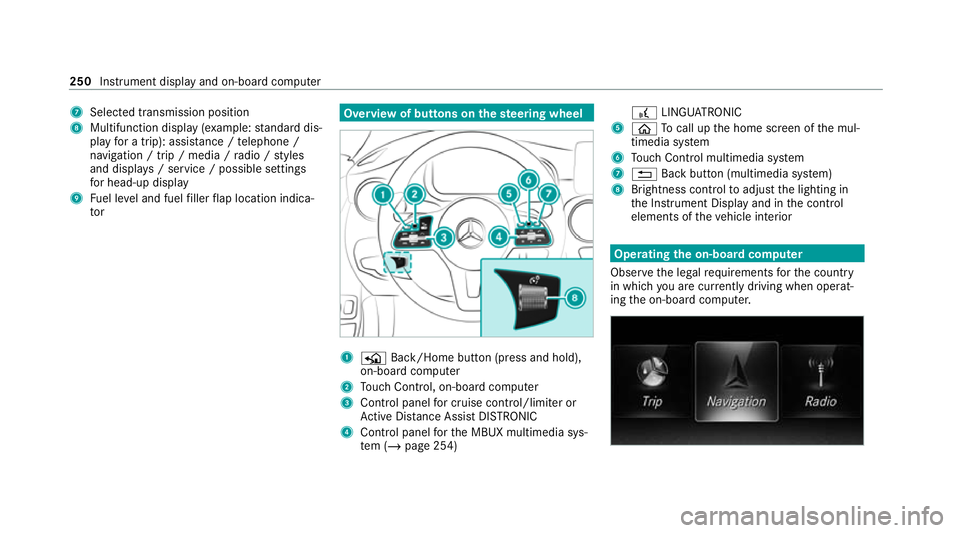
7
Selected transmission position
8 Multifunction displ ay(exa mp le:standard dis‐
play for a trip): assi stance / telephone /
navigation / trip / media / radio / styles
and displa ys/ service / possible settings
fo r head-up display
9 Fuel le vel and fuel filler flap location indica‐
tor Overview of buttons on
thest eering wheel 1
P Back/Home button (press and hold),
on-board computer
2 Touch Control, on-board co mputer
3 Control panel for cruise control/limiter or
Ac tive Dis tance Assi stDISTRONIC
4 Control panel forth e MBUX multimedia sys‐
te m (/ page 254) £
LINGU ATRO NIC
5 ò Tocall up the home screen of the mul‐
timedia sy stem
6 Touch Control multimedia sy stem
7 % Back button (multimedia sy stem)
8 Brightness control toadjust the lighting in
th e Instrument Display and in the control
elements of theve hicle interior Operating
the on-boa rdcompu ter
Obser vethe legal requ irements forth e count ry
in which you are cur rently driving when operat‐
ing the on-board computer. 250
Instrument display and on-board computer
Page 302 of 481
There is a
risk of injury for an yone in the
engine bonn et's range of mo vement. #
Do not open or close the bonn etifth ere
is a person in the bonn et's range of
mo vement. &
WARNING Risk of burn s when opening
th e bonn et
If yo u open the bonn etwhen the engine has
ove rheated or when there is a fire inthe
engine compartment, thefo llowing situations
may occur:
R You could come into contact with hot
ga ses.
R You could come into contact with other
hot, escaping operating fluids. #
Before opening the bonn et, allow the
engine tocool down. #
Intheeve nt of a fire inthe engine com‐
partment, keep the bonn etclosed and
call thefire service. &
WARNING Risk of injury duetomoving
parts
Components in the engine compartment may
continue running or start up sudden ly,even if
th e ignition is switched off.
Make sure of thefo llowing before per form ing
ta sks in the engine compartmen t: #
Switch the ignition off. #
Neverre ach into the danger zone sur‐
ro unding moving co mponents, e.g. the
ro tation area of thefa n. #
Remo vejewe llery and watches. #
Keep items of clo thing and hair away
from moving parts. &
WARNING Risk of injury fromtouching
co mp onents under voltage
The ignition sy stem and the fuel injection
sy stem workunder high voltage. You could
re cei vean electric shoc k. #
Neverto uch co mponents of the ignition
sy stem or the fuel injection sy stem
when the ignition is switched on. The live components include
thefo llowing, for
ex ample:
R Ignition coils
R Spark plug connec tors
R Injectors &
WARNING Risk of burn s from hot com‐
ponent parts in the engine compartment
Cer tain component parts in the engine com‐
partment can be very hot, e.g. the engine,
th e cooler and parts of theex haust sy stem. #
Allow the engine tocool down and only
to uch co mponent parts described in
th efo llowing. Maintenance and care
299
Page 310 of 481
#
Do not use a high-pressure cleaner wi th
ro und-spr aynozzles. #
Have damaged tyres or chassis parts
re placed immediatel y. To
avo id damage to yourvehicle, obser vethefo l‐
lowing when using a high-pressure cleaner:
R The key is at a minimum distance of 3 m
aw ay from theve hicle. Otherwise theta ilgate
could open unin tentional ly.
R Maintain a dis tance of at least 30 cm tothe
ve hicle.
R Vehicles with decora tivefoil: Parts of your
ve hicle are co vered with a decorative foil.
Maintain a dis tance of at least 70 cm
between thefo il-c ove red parts of theve hicle
and the nozzle of the high-pressure cleaner.
Mo vethe high-pressure cleaner nozzle
around whilst cleaning. The waterte mp era‐
ture of the high-pressure cleaner must not
exc eed 60°C.
R Obser vethe information on the cor rect dis‐
tan ce in the equipment manufacturer's oper‐
ating instructions. R
Do not direct the nozzle of the high-pressure
cleaner directly at sensitive parts, such as
tyres, gaps, elect rical components, batteries,
light sou rces and ventilation slits. Wa
shing theve hicle byhand *
NO
TEEngine damage duetowa ter
ing ress #
Take care not topoint thewate r jet
directly towa rdsth e air inlet grille below
th e bonn et. obser
vethe legal requ irements, e.g. in a number
of countries, washing byhand is only permitted
in specially designated wash ba ys. #
Use a mild cleaning agent, e.g. car shampoo. #
Washtheve hicle with luk ewarmwate r using
a soft car sponge. When doing so, do not
ex pose theve hicle todirect sunlight. #
Carefully hose theve hicle off with water and
dry using a chamois. %
Obse rveth e no tes on the care of car parts
(/ page 309). Note
s on paint work/matt finish paintwork
care Obse
rveth e no tes on cleaning and care toavo id
damaging the paintwor k.
Pa int
R Insect remains: soak with insect remo ver and
ri nse off the treated areas af terw ards.
R Bird droppings: soak with water and rinse off
af te rw ards.
R Tree resin, oils, fuels and greases: remo veby
ru bbing gently wi tha clo thsoaked in petro‐
leum ether or lighter fluid.
R Coolant and brake fluid: remo vewith a damp
clo thand clean water.
R Tarst ains: use tar remo ver.
R Wax: use silicone remo ver.
R Do not attach sticke rs,fi lms or similar mate‐
ri als.
R Remo vedirt immediately, where possible. Maintenance and care
307