Page 249 of 481

Tr
ailer hit ch(examp le with additional guide pin)
Depending on the bicycle rack 's design, dif fere nt
numbe rsof bicycles can be transpor ted.
The following bicycle rack designs are possible:
R When mounted byattaching toball head 1,
th e maximum load capacity is 75kg.Yo u can
transport up tothre e bicycles. R
When mounted on ball head 1and guide
pin 2, the maximum load capacity is
10 0kg .Yo u can transpo rtup tofour bicy‐
cles.
The maximum load capacity is calculated from
th ewe ight of the bicycle rack and the bicycle
ra ck load.
Obser vethe no tes on driving with a roof load,
trailer or fully laden vehicle (/ page157).
When using a bicyc lerack , set the tyre pressure
fo r increased load on there ar axle of theve hicle.
Fu rther information on the tyre pressure can be
fo und in the tyre pressure table (/ page 337).
Note s on loading
The larger the dis tance between the load's
cent reof gr avity and the ball head, the greater
th e load on the trailer hitch.
Obser vethefo llowing no tes:
R mount heavy bicycles as close totheve hicle
as possible
R always distribute the load on the bicycle rack
as eve nly as possible across theve hicle's
longitudinal axis Mercedes-Benz
recommends removing all
de tach able parts from bicycles (e.g. bask ets,
ch ild seats, rech arge able bat teries) before load‐
ing them onto the bicycle rack . This will impr ove
th e aerodynamic resis tance and centre of gr avity
of the bicycle rack.
Alw ays secure the bicycles toprev ent them from
moving around and check them at regular inter‐
va ls to ensure that they are secure.
Do not use tarp aulins or other co vers. The driv‐
ing characteristics and rear view may be
impaired. In addition, aerodynamic resis tance
and the load on the trailer hitch will increase. 246
Driving and pa rking
Page 250 of 481

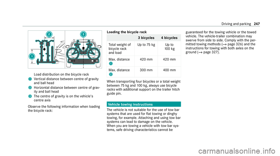
Load distribution on
the bicycle rack
1 Vertical dis tance between centre of gr avity
and ball head
2 Horizon tal dis tance between centre of gr av‐
ity and ball head
3 The centre of gr avity is on theve hicle's
centre axis
Obse rveth efo llowing information when loading
th e bicycle rack: Loading
the bicycle rack 3 bicycles 4 bicycles
To talwe ight of
bicycle rack
and load Up
to75 kg Up to
10 0kg
Max. dis tance
1 420 mm 420 mm
Max. di stance
2 300 mm 400 mm When transpo
rting four bic ycles or a totalwe ight
between 75kgand 100kg , alw ays use bicycle
ra ck s with additional support on the trailer hitch
guide pin. Ve
hicle towing instructions
The vehicle is not suitable forth e use of tow bar
sy stems that are used forflat towing or ding hy
to wing, forex ample. Attach ing and using tow bar
sy stems can lead todamage on theve hicle.
When you are towing a vehicle with tow bar sys‐
te ms, safe driving characteristics cannot be guaranteed
forth eto wing vehicle or theto wed
ve hicle. The vehicle-trailer combination may
swer vefrom side toside. Comply with the per‐
mitted towing me thods (/ page 326) and the
instructions forto wing with bo thaxles on the
ground (/ page 327). Driving and parking
247
Page 251 of 481

Note
s onthe instrument display and on-
board compu ter &
WARNING Risk of accident due toan
instrument display malfunction
If th e instrument display has failed or mal‐
functioned, the function restrictions applying
to saf etyre leva nt sy stems are not visible.
The operating saf ety of your vehicle may be
impaired. #
Drive on carefull y.#
Have theve hicle checked immediately
at a qualified specialist workshop. &
WARNING Risk of dist raction from infor‐
mation sy stems and communications
equipment
If yo u operate information and communica‐
tion equipment integ rated in theve hicle
when driving, you will be distracted from the
traf fic situation. This could also cause youto
lose control of theve hicle. #
Only operate this equipment when the
traf fic situation permits. #
Ifyo u cannot be sure of this, stop the
ve hicle whilst paying attention toroad
and traf fic conditions and ope rate the
equipment with theve hicle stationar y. *
NO
TEMercedes-AMG vehicles #
Obser vethe no tes in the Supplement.
Yo u could otherwise failto recognise
dangers. *
NO
TEPlug-in hybrid #
Obser vethe no tes in the Supplement.
Yo u could otherwise failto recognise
dangers. Yo
u must obse rveth e legal requirements forthe
country in whi chyou are cur rently driving when
operating the on-board computer.
The on-board computer sho wsonly display mes‐
sages and warnings from specific sy stems on th
e multifunction displa y.Yo u must therefore
ensure that your vehicle is alw aysre liable.
If th e operating saf ety of your vehicle is
impaired, park theve hicle immediately and in
accordance with the traf fic conditions. Contact a
qu alified specialist workshop. 248
Instrument display and on-board computer
Page 252 of 481
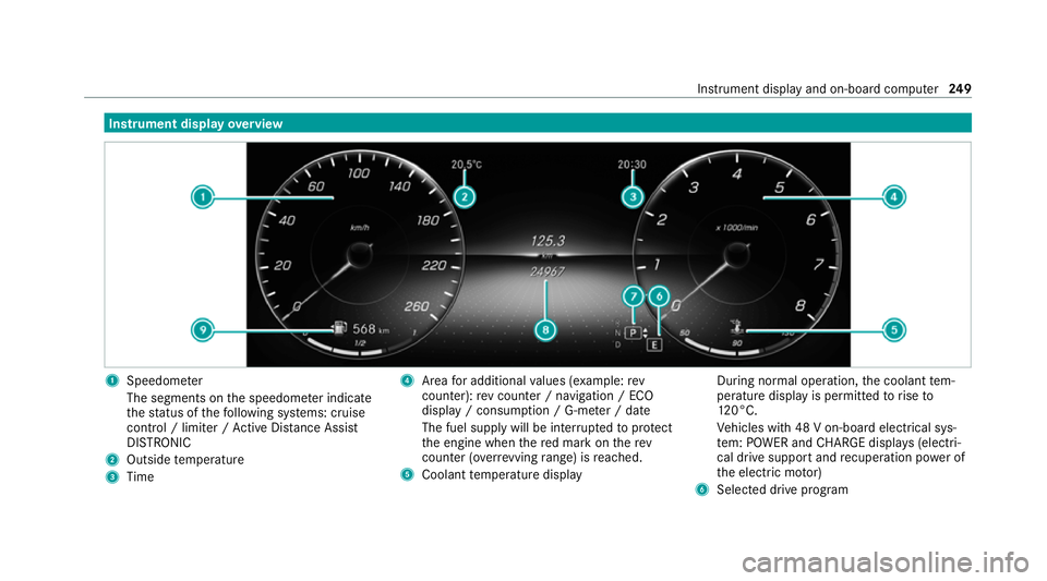
Instrument display
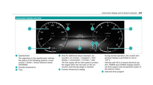
overview 1
Speedome ter
The segments on the speedome ter indica te
th est atus of thefo llowing sy stems: cruise
control / limiter / Active Dis tance Assi st
DISTRONIC
2 Outside temp erature
3 Time 4
Area for additional values (e xamp le:rev
counter): rev counter / navigation / ECO
display / consum ption / G-me ter / date
The fuel supply will be inter rupted toprotect
th e engine when there d mark on therev
counter (o verrev ving range) is reached.
5 Coolant temp erature display During normal operation,
the coolant tem‐
perature display is permitted torise to
12 0°C.
Ve hicles with 48 V on-board electrical sys‐
te m: POWER and CHARGE displ ays (electri‐
cal drive support and recuperation po wer of
th e electric mo tor)
6 Selected drive program Instrument display and on-board computer
249
Page 253 of 481

7
Selected transmission position
8 Multifunction displ ay(exa mp le:standard dis‐
play for a trip): assi stance / telephone /
navigation / trip / media / radio / styles
and displa ys/ service / possible settings
fo r head-up display
9 Fuel le vel and fuel filler flap location indica‐
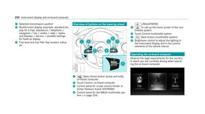
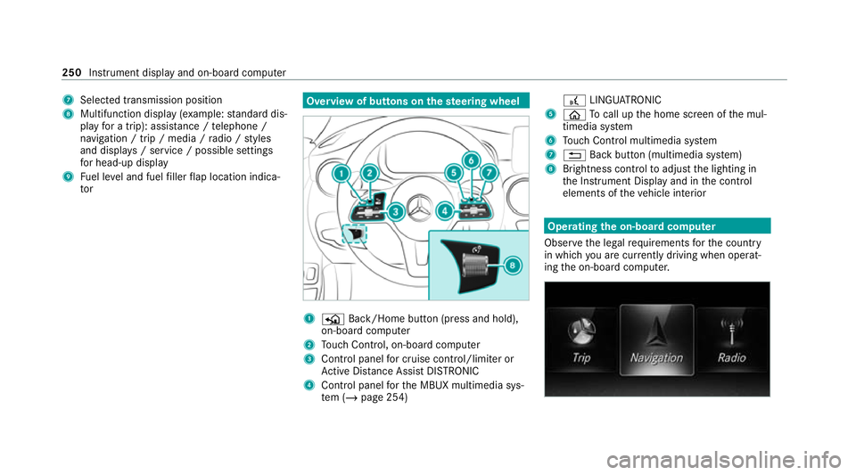
tor Overview of buttons on
thest eering wheel 1
P Back/Home button (press and hold),
on-board computer
2 Touch Control, on-board co mputer
3 Control panel for cruise control/limiter or
Ac tive Dis tance Assi stDISTRONIC
4 Control panel forth e MBUX multimedia sys‐
te m (/ page 254) £
LINGU ATRO NIC
5 ò Tocall up the home screen of the mul‐
timedia sy stem
6 Touch Control multimedia sy stem
7 % Back button (multimedia sy stem)
8 Brightness control toadjust the lighting in
th e Instrument Display and in the control
elements of theve hicle interior Operating
the on-boa rdcompu ter
Obser vethe legal requ irements forth e count ry
in which you are cur rently driving when operat‐
ing the on-board computer. 250
Instrument display and on-board computer
Page 254 of 481

The on-board computer is operated using
the
left-hand Touch Control and the left-hand back/
home button.
When the on-board computer is being operated,
dif fere nt acoustic signals will sound as operating
fe edbac k,e.g. when the end of a list is reached
or when you are sc rolling thro ugh a list.
The following menus are available:
R Service
R Assistance
R Trip
R Navigation
R Radio
R Media
R Telephone
R HUD
R Vehicles with an instrument display in
th e widescreen cockpit: Design
% You can find information about the possible
settings and selections on the menus in the
Digital Owner's Manual. #
Tocall up the menu bar: pressthe left-hand
back button until the menu bar is displa yed.
% Press theò button tocall up the menu
bar of the on-board computer. #
Toscroll on the menu bar: swipe left or
ri ght on the left-hand Touch Control. #
Tocall up a menu, submenu or possible
settings on the menu, or confirm a selec‐
tion or setting: pressthe left-hand Touch
Control. #
Toscroll through displa ysor lists on the
menu, or select display content, a func‐
tion, an entry or a displa y:swipe upwards
or down wards on the left-hand Touch Con‐
trol. #
Toswitch between displa ys:swipe
upwards or down wards on the left-hand
To uch Control. #
Toexit a submenu: pressthe left-hand back
button. Overview of displa
yson the multifunction
display
Displa yson the multifunction display:
ë Active Parking Assist activated
(/ page 234)
é Parking Assist PARKTRONIC deacti vated
( / page 231)
¯ Cruise control (/
page193)
È Limi
ter (/ page194)
ç Active Dis tance Assi stDISTRONIC
(/ page 196)
æ Ac
tive Brake Assi st (/ page 210)
è Active Steering Assist (/ page 203)
à Ac
tive Lane Keeping Assist (/ page215)
è ECO
start/ stop function (/ page160)
ë HOLD fu
nction (/ page 190)
_ Ad
aptive Highbeam Assist (/ page132)
Ad aptive Highbeam Assist Plus
(/ page 133)
ð Maximum pe rmissible speed exceeded
(for cer tain countries only) Instrument display and on-board computer
251
Page 255 of 481

Ve
hicles with Traf fic Sign Assis t:de tected
instructions and traf fic signs (/ page 210). Head-up display
Fu
nction of the head-up display *
NO
TEMercedes-AMG vehicles #
Obser vethe no tes in the Supplement.
Yo u could otherwise failto recognise
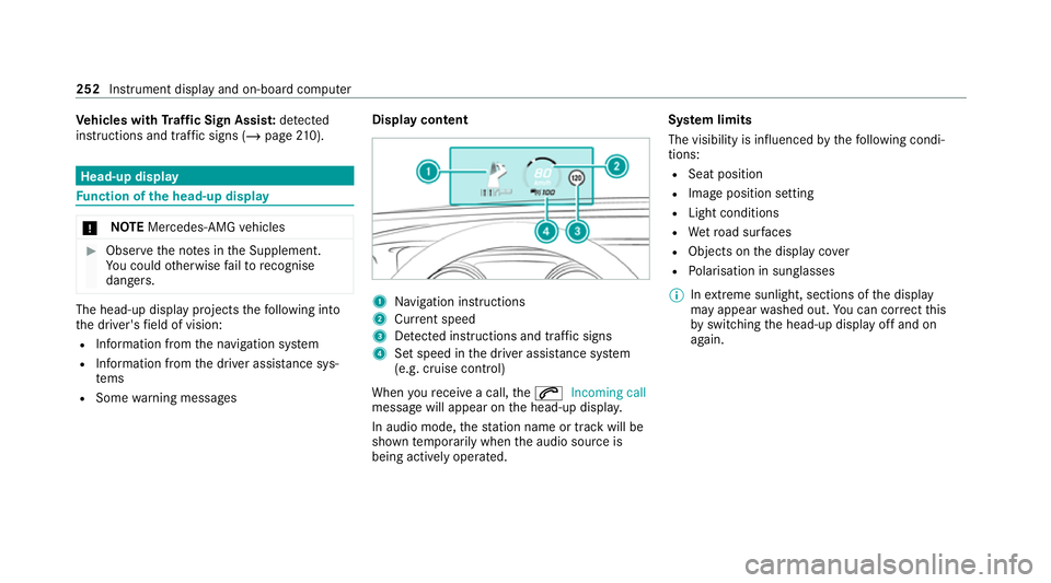
dangers. The head-up displ
ayprojects thefo llowing into
th e driver's field of vision:
R Information from the navigation sy stem
R Information from the driver assis tance sys‐
te ms
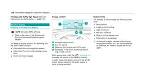
R Some warning messages Display content 1
Navigation instructions
2 Curr ent speed
3 Detected instructions and traf fic signs
4 Set speed in the driver assis tance sy stem
(e.g. cruise control)
When youre cei vea call, the6 Incoming call
message will appear on the head-up displa y.
In audio mode, thest ation name or track will be
shown temp orarily when the audio source is
being actively operated. Sy
stem limits
The visibility is influenced bythefo llowing condi‐
tions:
R Seat position
R Image position setting
R Light conditions
R Wetro ad sur faces
R Objects on the display co ver
R Polarisation in sunglasses
% Inextreme sunlight, sections of the display
may appear washed out. You can co rrect this
by switching the head-up display off and on
again. 252
Instrument display and on-board computer
Page 256 of 481
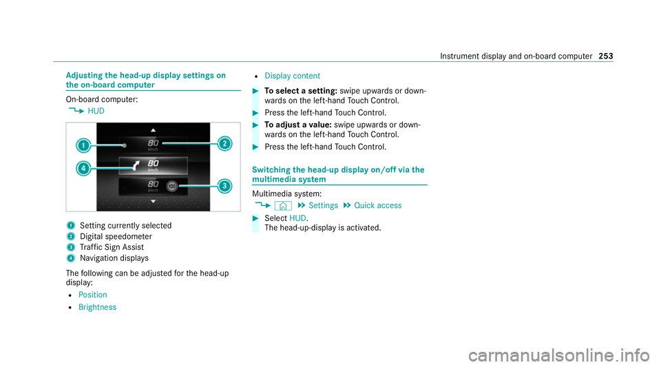
Ad
justing the head-up display settings on
the on-board co mputer On-board computer:
4 HUD 1
Setting cur rently selected
2 Digital speedome ter
3 Traf fic Sign Assi st
4 Navigation displa ys
The following can be adjus tedfo rth e head-up
display:
R Position
R Brightness R
Display content #
Toselect a setting: swipe upwards or down‐
wa rds on the left-hand Touch Control. #
Press the left-hand Touch Control. #
Toadjust a value: swipe upwards or down‐
wa rds on the left-hand Touch Control. #
Press the left-hand Touch Control. Swit
ching the head-up display on/off via the
mu ltimedia sy stem Multimedia sy
stem:
4 © 5
Settings 5
Quick access #
Select HUD.
The head-up-display is activated. Instrument display and on-board computer
253