2021 LINCOLN CORSAIR light
[x] Cancel search: lightPage 224 of 638

EMISSION LAW
WARNING: Do not remove or alter
the original equipment floor covering or
insulation between it and the metal floor
of the vehicle. The floor covering and
insulation protect occupants of the vehicle
from the engine and exhaust system heat
and noise. On vehicles with no original
equipment floor covering insulation, do not
carry passengers in a manner that permits
prolonged skin contact with the metal floor.
Failure to follow these instructions may
result in fire or personal injury.
U.S. federal laws and certain state laws
prohibit removing or rendering inoperative
emission control system components. Similar
federal or provincial laws may apply in
Canada. We do not approve of any vehicle
modification without first determining
applicable laws. Tampering with emissions control
systems including related sensors
or the Diesel Exhaust Fluid system
can result in reduced engine power and the
illumination of the service engine soon light.
Tampering With a Noise Control
System
Federal laws prohibit the following acts:
• Removal or rendering inoperative by any
person other than for purposes of
maintenance.
• Repair or replacement of any device or
element of the design incorporated into
a new vehicle for the purpose of noise
control prior to its sale or delivery to the
ultimate purchaser or while it is in use.
• The use of the vehicle after any person
removes or renders inoperative any
device or element of the design. The U.S. Environmental Protection Agency
may presume to constitute tampering as
follows:
•
Removal of hood blanket, fender apron
absorbers, fender apron barriers,
underbody noise shields or acoustically
absorptive material.
• Tampering or rendering inoperative the
engine speed governor, to allow engine
speed to exceed manufacturer
specifications.
If the engine does not start, runs rough,
experiences a decrease in engine
performance, experiences excess fuel
consumption or produces excessive exhaust
smoke, check for the following:
• A plugged or disconnected air inlet
system hose.
• A plugged engine air filter element.
• Water in the fuel filter and water
separator.
• A clogged fuel filter.
• Contaminated fuel.
• Air in the fuel system, due to loose
connections.
221
Corsair (CTF) Canada/United States of America, enUSA, Edition date: 202007, First-Printing Engine Emission Control
Page 226 of 638

The scheduled maintenance items listed in
scheduled maintenance information are
essential to the life and performance of your
vehicle and to its emissions system.
If you use anything other than Ford,
Motorcraft or Ford-authorized parts for
maintenance replacements or for service of
components affecting emission control, such
non-Ford parts should be equivalent to
genuine Ford Motor Company parts in
performance and durability.
Illumination of the service engine soon
indicator, charging system warning light or
the temperature warning light, fluid leaks,
strange odors, smoke or loss of engine
power could indicate that the emission
control system is not working properly.
An improperly operating or damaged exhaust
system may allow exhaust to enter the
vehicle. Have a damaged or improperly
operating exhaust system inspected and
repaired immediately.
Do not make any unauthorized changes to
your vehicle or engine. By law, vehicle
owners and anyone who manufactures,
repairs, services, sells, leases, trades
vehicles, or supervises a fleet of vehicles are
not permitted to intentionally remove an
emission control device or prevent it from
working. Information about your vehicle
’s
emission system is on the Vehicle Emission
Control Information Decal located on or near
the engine. This decal also lists engine
displacement.
Please consult your warranty information for
complete details.
On-Board Diagnostics (OBD-II)
Your vehicle has a computer known as the
on-board diagnostics system (OBD-II) that
monitors the engine ’s emission control
system. The system protects the environment
by making sure that your vehicle continues
to meet government emission standards. The
OBD-II system also assists a service
technician in properly servicing your vehicle. When the service engine soon
indicator illuminates, the OBD-II
system has detected a malfunction.
Temporary malfunctions may cause the
service engine soon indicator to illuminate.
Examples are:
1. Your vehicle has run out of fuel—the engine may misfire or run poorly.
2. Poor fuel quality or water in the fuel—the
engine may misfire or run poorly.
3. The fuel fill inlet may not have closed properly. See Refueling (page 216).
4. Driving through deep water—the electrical system may be wet.
You can correct these temporary
malfunctions by filling the fuel tank with good
quality fuel, properly closing the fuel fill inlet
or letting the electrical system dry out. After
three driving cycles without these or any
other temporary malfunctions present, the
service engine soon indicator should stay off
the next time you start the engine. A driving
cycle consists of a cold engine startup
followed by mixed city and highway driving.
No additional vehicle service is required.
223
Corsair (CTF) Canada/United States of America, enUSA, Edition date: 202007, First-Printing Engine Emission Control
Page 229 of 638
WARNING: Do not allow charging
equipment to be immersed in water or
liquids. Failure to follow this warning could
result in fire, serious personal injury or
death. WARNING:
Do not attempt to open
the charging equipment. Failure to follow
this instruction could result in personal
injury, death or property damage. WARNING:
Do not use the charging
equipment if it is faulty or has been
damaged. Failure to follow this instruction
could result in personal injury, death or
property damage. WARNING: You risk death or serious
injury to yourself and others if you do not
follow the instruction highlighted by the
warning symbol. Failure to follow the
specific warnings and instructions could
result in personal injury. WARNING:
Install charging
equipment in compliance with local
regulations. Failure to follow this warning
could result in fire, serious personal injury
or death. WARNING:
Do not use an
ungrounded wall outlet. If you suspect that
the wall outlet is not properly grounded,
have a qualified electrician inspect the wall
outlet. Failure to follow this instruction
could result in personal injury or death. WARNING:
Do not modify the
convenience cord plug. If the convenience
cord plug does not properly fit into the wall
outlet, have a qualified electrician install
the correct wall outlet. Failure to follow this
instruction could result in personal injury
or death. OPERATION INSTRUCTIONS
•
Read all the instructions before using this
product.
• Supervise this device when in use around
children.
• Do not put fingers into the electric vehicle
connector.
• Do not use this product if the flexible
power cord or electric vehicle cable has
broken insulation, or any other signs of
damage.
• Do not use this product if the enclosure
or the electric vehicle connector is
broken, cracked, open, or shows any
other indication of damage.
Note: Ground this product. If it malfunctions
or breaks down, grounding provides a path
of least resistance for electric current to
reduce the risk of electric shock. This product
comes with a cord having an equipment
grounding conductor and a grounding plug.
Make sure you plug it into an appropriate
outlet that is properly installed and grounded
in accordance with all local codes and
ordinances.
226
Corsair (CTF) Canada/United States of America, enUSA, Edition date: 202007, First-Printing High Voltage Battery
(If Equipped)
Page 230 of 638
Charging Equipment
Your vehicle has a convenience cord in the
luggage compartment.
Note:
You need to plug the convenience
cord into a dedicated outlet.
Note: Firmly fit the AC wall plug into the AC
outlet. If the connection feels loose, worn or
the AC outlet is damaged, please have a
qualified electrician replace the AC outlet.
Using a convenience cord with a worn outlet
could cause burns, property damage and
increase the risk of electric shock.
Note: Do not use the 120 volt convenience
cord with an extension cord, two-prong
adapter, surge protector, timer or other
adapter.
Note: If charging for your plug-in vehicle fails,
please call the Customer Relationship
Center, or click on Call for support or Live
Chat at our website. CAUTION: TO REDUCE THE RISK OF FIRE-
Use a three-prong AC outlet that is properly
grounded, 15-20 amps or greater, and in
good condition. Use a dedicated line. You
cannot have other appliances connected to
the same circuit. If you do not use a
dedicated circuit, the circuit breaker could
trip or open. If you do not have a dedicated
circuit, contact a licensed professional
electrician for proper installation.
Note: Make sure the electrical source meets
the requirements for the high-voltage
batteries to charge.
Make sure that the convenience cord is
completely unwrapped before charging.
Always plug the cord into the AC outlet
before connecting the charged coupler into
the charge port on your vehicle.
Note: If the power indicator light is off after
plugging in the convenience cord and you
cannot determine a charge status, use a
different outlet.
Note: Store the convenience cord in a clean
dry place between the temperature of
-39.9–157.9°F (-40–70°C) Note:
For further information on the
convenience cord, please refer to the user
manual provided with the convenience cord.
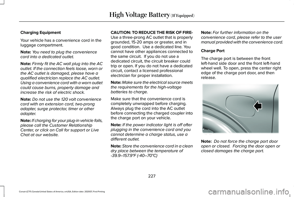
Charge Port
The charge port is between the front
left-hand side door and the front left-hand
wheel well. To open, press the center right
edge of the charge port door, and then
release. Note:
Do not force the charge port door
open or closed. Forcing the door open or
closed damages the charge port.
227
Corsair (CTF) Canada/United States of America, enUSA, Edition date: 202007, First-Printing High Voltage Battery
(If Equipped)E295258
Page 231 of 638
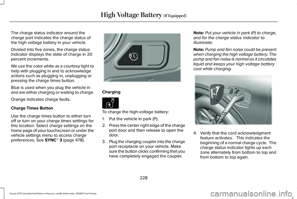
The charge status indicator around the
charge port indicates the charge status of
the high voltage battery in your vehicle.
Divided into five zones, the charge status
indicator displays the state of charge in 20
percent increments.
We use the color white as a courtesy light to
help with plugging in and to acknowledge
actions such as plugging in, unplugging or
pressing the charge times button.
Blue is used when you plug the vehicle in
and are either charging or waiting to charge.
Orange indicates charge faults.
Charge Times Button
Use the charge times button to either turn
off or turn on your charge times settings for
this location. Select charge settings on the
home page of your touchscreen or under the
vehicle settings menu to access charge
preferences. See SYNC™ 3 (page 478).
Charging
To charge the high-voltage battery:
1. Put the vehicle in park (P).
2.
Press the center right edge of the charge
port door and then release to open the
door.
3. Plug the charging coupler into the charge
port receptacle on your vehicle. Make
sure the button clicks confirming that you
have completely engaged the coupler. Note:
Put your vehicle in park (P) to charge,
and for the charge status indicator to
illuminate.
Note: Pump and fan noise could be present
when charging the high voltage battery. The
pump and fan noise is normal as it circulates
liquid and keeps your high voltage battery
cool while charging. 4. Verify that the cord acknowledgment
feature activates. This indicates the
beginning of a normal charge cycle. The
charge status indicator lights up each
zone alternately from bottom to top and
from bottom to top again.
228
Corsair (CTF) Canada/United States of America, enUSA, Edition date: 202007, First-Printing High Voltage Battery
(If Equipped)E301111 E306676 E295257
Page 232 of 638
5. If using a charging station, follow the
instructions on the charge station to
begin the charging process.
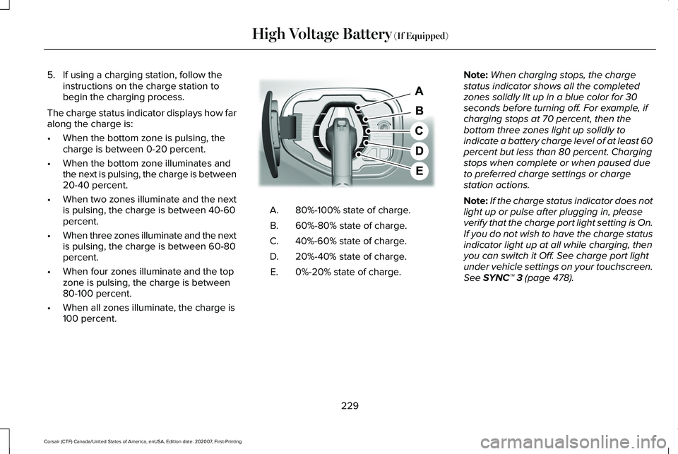
The charge status indicator displays how far
along the charge is:
• When the bottom zone is pulsing, the
charge is between 0-20 percent.
• When the bottom zone illuminates and
the next is pulsing, the charge is between
20-40 percent.
• When two zones illuminate and the next
is pulsing, the charge is between 40-60
percent.
• When three zones illuminate and the next
is pulsing, the charge is between 60-80
percent.
• When four zones illuminate and the top
zone is pulsing, the charge is between
80-100 percent.
• When all zones illuminate, the charge is
100 percent. 80%-100% state of charge.
A.
60%-80% state of charge.
B.
40%-60% state of charge.
C.
20%-40% state of charge.
D.
0%-20% state of charge.
E. Note:
When charging stops, the charge
status indicator shows all the completed
zones solidly lit up in a blue color for 30
seconds before turning off. For example, if
charging stops at 70 percent, then the
bottom three zones light up solidly to
indicate a battery charge level of at least 60
percent but less than 80 percent. Charging
stops when complete or when paused due
to preferred charge settings or charge
station actions.
Note: If the charge status indicator does not
light up or pulse after plugging in, please
verify that the charge port light setting is On.
If you do not wish to have the charge status
indicator light up at all while charging, then
you can switch it Off. See charge port light
under vehicle settings on your touchscreen.
See SYNC™ 3 (page 478).
229
Corsair (CTF) Canada/United States of America, enUSA, Edition date: 202007, First-Printing High Voltage Battery
(If Equipped)E301197
Page 233 of 638
Note:
You can identify charging faults by the
color orange on the charge status indicator.
Faults can occur within the vehicle charging
system or outside the vehicle, such as with
the charge cord, charge station or electrical
supply.
Note: If the system detects a fault in the
vehicle charging system at any point in a
charge cycle, the entire charge status
indicator lights up solidly in an orange color
for 30 seconds and then turns off. If this
happens, unplug the charging coupler and
then plug it back into the charge port
receptacle. If the problem persists, have your
vehicle checked as soon as possible.
Note: If the system detects a fault outside
the vehicle, such as with the charge station
or charge cord, the entire charge status
indicator flashes continuously for 30 seconds
and then turns off. If this happens, check the
charge cord and the charge station or
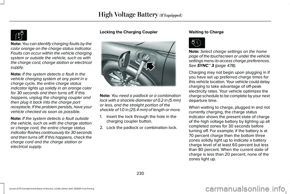
electrical supply. Locking the Charging Coupler
Note:
You need a padlock or a combination
lock with a shackle diameter of 0.2 in (5 mm)
or less, and the straight portion of the
shackle of 1.0 in (25.4 mm) of length or more.
1. Insert the lock through the hole in the charging coupler button.
2. Lock the padlock or combination lock. Waiting to Charge Note:
Select charge settings on the home
page of the touchscreen or under the vehicle
settings menu to access charge preferences.
See SYNC™ 3 (page 478).
Charging may not begin upon plugging in if
you have set up preferred charge times for
this vehicle location. Your vehicle could delay
charging to take advantage of off-peak
electricity rates. Your vehicle optimizes the
charge schedule to be complete by your next
departure time.
When waiting to charge, plugged in and not
currently charging, the charge status
indicator shows the present state of charge
of the high voltage battery by lighting up all
completed zones for 30 seconds before
turning off. For example, if the battery is at
70 percent charge then the bottom three
zones solidly light up to indicate a battery
charge level of at least 60 percent but less
than 80 percent. When the current state of
charge is less than 20 percent, none of the
zones light up.
230
Corsair (CTF) Canada/United States of America, enUSA, Edition date: 202007, First-Printing High Voltage Battery
(If Equipped)E306677 E295451 E306678
Page 239 of 638
11.
Once it is safe to do so, and there is no
risk that your vehicle will roll,
disconnect the negative, black, battery
cable from the battery. If the vehicle
rolls before the battery is disconnected,
the electric parking brake may
automatically apply. The operator may
need to release the parking brake
again. See Electric Parking Brake
(page 246).
Returning Your Vehicle to Normal Mode
1. Once it is safe to do so, reconnect the negative, black, battery cable to the
battery.
2. Apply the parking brake.
See Electric
Parking Brake (page 246).
Note: If the vehicle battery is dead, for
example, no electrical power is available,
you could require external power to apply
the parking brake.
3. Fully apply the brake pedal and hold, do
not release. Pull the orange tether
outward toward the driver seat to remove
it from the override position. 4. The cable releases and retracts back to
its original rest position.
5. Stow the manual park release cable tether back inside the instrument panel
dash hole, and install the access cover
by pressing it back in position.
6. With your foot fully applied on the brake
pedal, start your vehicle. Confirm that
your vehicle is in the park (P) position and
that the instrument cluster indicates park
(P).
7. If the instrument cluster is not displaying
the park (P) position or there is a
message stating Park Not Available,
Transmission Not In Park, or Shift System
Fault, apply the parking brake before
exiting your vehicle. Contact an
authorized dealer for service. Automatic Transmission Adaptive
Learning
This feature may increase durability and
provide consistent shift feel over the life of
your vehicle. A new vehicle or transmission
may have firm shifts, soft shifts or both. This
is normal and does not affect the operation
or durability of the transmission. Over time,
the adaptive learning process fully updates
transmission operation.
If Your Vehicle Gets Stuck in Mud or
Snow
If your vehicle gets stuck in mud or snow,
you can rock it out by shifting between
forward and reverse gears, stopping
between shifts in a steady pattern. Press
lightly on the accelerator in each gear.
Note:
Do not rock your vehicle if the engine
is not at normal operating temperature or
damage to the transmission could occur.
Note: Do not rock your vehicle for more than
a minute or damage to the transmission and
tires could occur, or the engine may
overheat.
236
Corsair (CTF) Canada/United States of America, enUSA, Edition date: 202007, First-Printing Transmission