2021 LINCOLN CORSAIR light
[x] Cancel search: lightPage 341 of 638
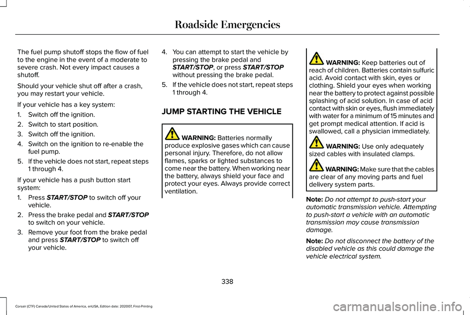
The fuel pump shutoff stops the flow of fuel
to the engine in the event of a moderate to
severe crash. Not every impact causes a
shutoff.
Should your vehicle shut off after a crash,
you may restart your vehicle.
If your vehicle has a key system:
1. Switch off the ignition.
2. Switch to start position.
3. Switch off the ignition.
4. Switch on the ignition to re-enable the
fuel pump.
5. If the vehicle does not start, repeat steps
1 through 4.
If your vehicle has a push button start
system:
1. Press START/STOP to switch off your
vehicle.
2. Press the brake pedal and
START/STOP
to switch on your vehicle.
3. Remove your foot from the brake pedal and press
START/STOP to switch off
your vehicle. 4. You can attempt to start the vehicle by
pressing the brake pedal and
START/STOP
, or press START/STOP
without pressing the brake pedal.
5. If the vehicle does not start, repeat steps
1 through 4.
JUMP STARTING THE VEHICLE WARNING:
Batteries normally
produce explosive gases which can cause
personal injury. Therefore, do not allow
flames, sparks or lighted substances to
come near the battery. When working near
the battery, always shield your face and
protect your eyes. Always provide correct
ventilation. WARNING:
Keep batteries out of
reach of children. Batteries contain sulfuric
acid. Avoid contact with skin, eyes or
clothing. Shield your eyes when working
near the battery to protect against possible
splashing of acid solution. In case of acid
contact with skin or eyes, flush immediately
with water for a minimum of 15 minutes and
get prompt medical attention. If acid is
swallowed, call a physician immediately. WARNING:
Use only adequately
sized cables with insulated clamps. WARNING: Make sure that the cables
are clear of any moving parts and fuel
delivery system parts.
Note: Do not attempt to push-start your
automatic transmission vehicle. Attempting
to push-start a vehicle with an automatic
transmission may cause transmission
damage.
Note: Do not disconnect the battery of the
disabled vehicle as this could damage the
vehicle electrical system.
338
Corsair (CTF) Canada/United States of America, enUSA, Edition date: 202007, First-Printing Roadside Emergencies
Page 357 of 638
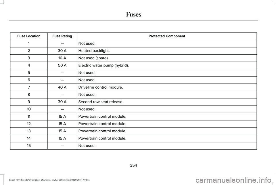
Protected Component
Fuse Rating
Fuse Location
Not used.
—
1
Heated backlight.
30 A
2
Not used (spare).
10 A
3
Electric water pump (hybrid).
50 A
4
Not used.
—
5
Not used.
—
6
Driveline control module.
40 A
7
Not used.
—
8
Second row seat release.
30 A
9
Not used.
—
10
Powertrain control module.
15 A
11
Powertrain control module.
15 A
12
Powertrain control module.
15 A
13
Powertrain control module.
15 A
14
Not used.
—
15
354
Corsair (CTF) Canada/United States of America, enUSA, Edition date: 202007, First-Printing Fuses
Page 358 of 638
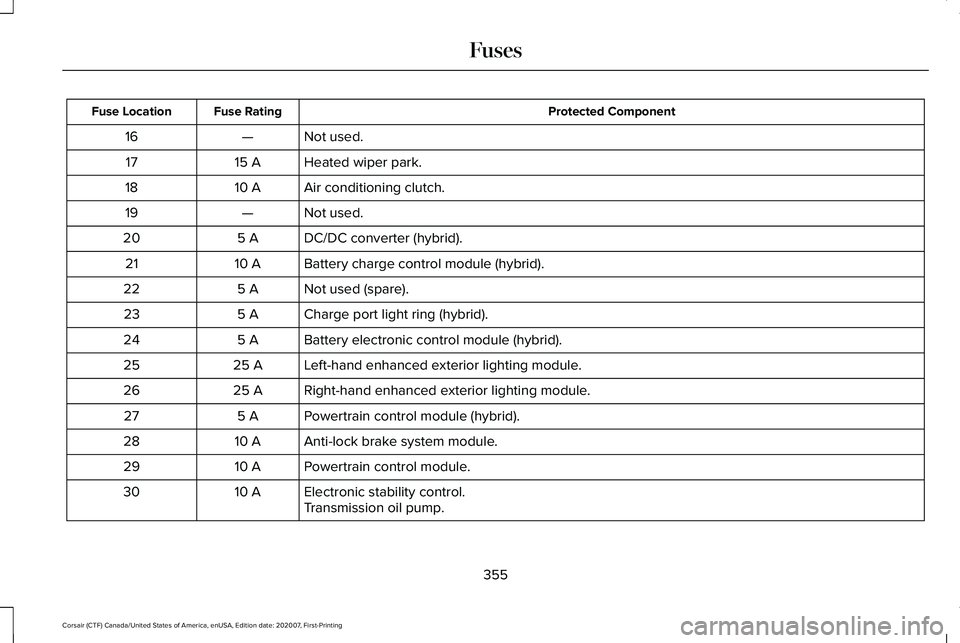
Protected Component
Fuse Rating
Fuse Location
Not used.
—
16
Heated wiper park.
15 A
17
Air conditioning clutch.
10 A
18
Not used.
—
19
DC/DC converter (hybrid).
5 A
20
Battery charge control module (hybrid).
10 A
21
Not used (spare).
5 A
22
Charge port light ring (hybrid).
5 A
23
Battery electronic control module (hybrid).
5 A
24
Left-hand enhanced exterior lighting module.
25 A
25
Right-hand enhanced exterior lighting module.
25 A
26
Powertrain control module (hybrid).
5 A
27
Anti-lock brake system module.
10 A
28
Powertrain control module.
10 A
29
Electronic stability control.
10 A
30
Transmission oil pump.
355
Corsair (CTF) Canada/United States of America, enUSA, Edition date: 202007, First-Printing Fuses
Page 377 of 638

6. Wipe any dirt or debris from the air filter
housing assembly to make sure no dirt
gets in the engine and to make sure you
have a good seal. 7.
Install a new air filter element. Be careful
not to crimp the filter element edges
between the air filter housing and cover.
This could cause filter damage and allow
unfiltered air to enter the engine if it is
not properly seated.
8. Install the air filter housing cover. 9. Engage the clips to secure the air filter
housing cover to the air filter housing.
10. Reconnect the boot to the air filter housing cover and tighten securely.
ENGINE COOLANT CHECK WARNING: Do not remove the
coolant reservoir cap when the engine is
on or the cooling system is hot. Wait 10
minutes for the cooling system to cool
down. Cover the coolant reservoir cap with
a thick cloth to prevent the possibility of
scalding and slowly remove the cap.
Failure to follow this instruction could result
in personal injury. WARNING: Do not put coolant in the
windshield washer reservoir. If sprayed on
the windshield, coolant could make it
difficult to see through the windshield. WARNING:
To reduce the risk of
personal injury, make sure the engine is
cool before unscrewing the coolant
pressure relief cap. The cooling system is
under pressure. Steam and hot liquid can
come out forcefully when you loosen the
cap slightly. WARNING:
Do not add coolant
further than the MAX mark.
When the engine is cold, check the
concentration and level of the coolant at the
intervals listed in the scheduled maintenance
information.
See Scheduled Maintenance
(page 550).
Note: Make sure that the coolant level is
between the
MIN and MAX marks on the
coolant reservoir.
Note: Coolant expands when it is hot. The
level may extend beyond the
MAX mark.
374
Corsair (CTF) Canada/United States of America, enUSA, Edition date: 202007, First-Printing MaintenanceE299074
Page 383 of 638

1. Park your vehicle on a level surface.
2. Look at the brake fluid reservoir to see
where the brake fluid level is relative to
the MIN and the MAX marks on the
reservoir.
Note: If the brake fluid level is between the
MIN
and the MAX marks on the reservoir, it
is acceptable. Note:
If the brake fluid level is below the MIN
mark or above the
MAX mark, have your
vehicle checked as soon as possible.
Note: To avoid fluid contamination, the
reservoir cap must remain in place and fully
tight, unless you are adding fluid.
Only use fluid that meets our specifications.
See
Capacities and Specifications (page
433).
Brake Fluid Service Interval
Brake fluid absorbs water over time which
degrades the effectiveness of the brake fluid.
Change the brake fluid at the specified
intervals to prevent degraded braking
performance.
For detailed interval information, see
Scheduled Maintenance in your Owner's
Manual or your local maintenance guide.
POWER STEERING FLUID CHECK
Your vehicle is equipped with an electric
power steering (EPS) system. There is no
fluid reservoir to check or fill. CHANGING THE 12V BATTERY WARNING:
Batteries normally
produce explosive gases which can cause
personal injury. Therefore, do not allow
flames, sparks or lighted substances to
come near the battery. When working near
the battery, always shield your face and
protect your eyes. Always provide correct
ventilation. WARNING:
When lifting a
plastic-cased battery, excessive pressure
on the end walls could cause acid to flow
through the vent caps, resulting in personal
injury and damage to the vehicle or battery.
Lift the battery with a battery carrier or with
your hands on opposite corners.
380
Corsair (CTF) Canada/United States of America, enUSA, Edition date: 202007, First-Printing MaintenanceE170684
Page 385 of 638

Remove and Reinstall the Battery
To disconnect or remove the battery, do the
following:
1. Apply the parking brake and switch the
ignition off.
2. Switch all electrical equipment off, for example lights and radio.
3. Wait a minimum of two minutes before disconnecting the battery.
Note: The engine management system has
a power hold function and remains powered
for a period of time after you switch the
ignition off. This is to allow diagnostic and
adaptive tables to be stored. Disconnecting
the battery without waiting can cause
damage not covered by the vehicle
Warranty.
4. Disconnect the negative battery cable terminal.
5. Disconnect the positive battery cable terminal.
6. Remove the battery securing clamp.
7. Remove the battery.
8. To install, reverse the removal procedure. Note:
Before reconnecting the battery, make
sure the ignition remains switched off.
Note: Make sure the battery cable terminals
are fully tightened.
If you disconnect or replace the vehicle
battery, you must reset the following
features:
• Window bounce-back. See Windows
and Mirrors (page 112).
• Clock Settings.
• Pre-set radio stations.
• Steering Angle Sensor.
Note: To calibrate the steering angle sensor,
drive the vehicle above
30 mph (50 km/h)
for a minimum of 1.2 mi (2 km). Make sure to
drive straight ahead for a minimum of 30
seconds. Several vehicle functions are
disabled and a warning light could appear
until the sensor is calibrated. Note:
For flexible fuel vehicles, if you are
operating on E85, you could experience poor
starts or an inability to start the engine, and
driveability problems until the fuel trim and
ethanol content have been relearned. Drive
the vehicle at least
10 mi (16 km) to
completely relearn the idle trim and fuel trim
strategy.
Battery Disposal Make sure that you dispose of old
batteries in an environmentally
friendly way. Seek advice from
your local authority about recycling old
batteries.
ADJUSTING THE HEADLAMPS
Vertical Aim Adjustment
The assembly plant properly aims the
headlamps on your vehicle. If your vehicle
has been in an accident, have the alignment
of your headlamps checked by your
authorized dealer.
382
Corsair (CTF) Canada/United States of America, enUSA, Edition date: 202007, First-Printing MaintenanceE107998
Page 386 of 638
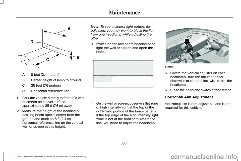
8 feet (2.4 meters)
A
Center height of lamp to ground
B
25 feet (7.6 meters)
C
Horizontal reference line
D
1. Park the vehicle directly in front of a wall
or screen on a level surface,
approximately 25 ft (7.6 m) away.
2. Measure the height of the headlamp passing beam optical center from the
ground and mark an
8 ft (2.4 m)
horizontal reference line on the vertical
wall or screen at this height. Note:
To see a clearer light pattern for
adjusting, you may want to block the light
from one headlamp while adjusting the
other.
3. Switch on the low beam headlamps to light the wall or screen and open the
hood. 4.
On the wall or screen, observe a flat zone
of high intensity light at the top of the
right-hand portion of the beam pattern.
If the top edge of the high intensity light
zone is not at the horizontal reference
line, you need to adjust the headlamp. 5. Locate the vertical adjuster on each
headlamp. Turn the adjuster either
clockwise or counterclockwise to aim the
headlamp.
6. Close the hood and switch off the lamps.
Horizontal Aim Adjustment
Horizontal aim is non-adjustable and is not
required for this vehicle.
383
Corsair (CTF) Canada/United States of America, enUSA, Edition date: 202007, First-Printing MaintenanceE142592 E142465 E171165
Page 388 of 638
Note:
Do not hold the wiper blade when
lifting the wiper arm.
Note: Make sure that the wiper arm does
not spring back against the glass when the
wiper blade is not attached.
2. Slightly rotate the wiper blade.
3. Remove the wiper blade.
4. Install in the reverse order.
Note: Make sure that the wiper blade locks
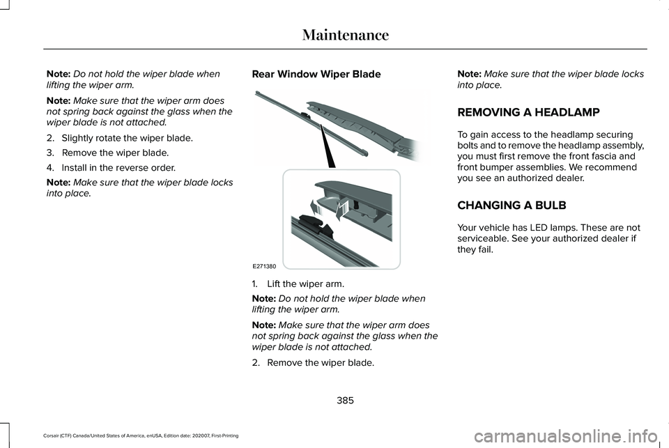
into place. Rear Window Wiper Blade 1. Lift the wiper arm.
Note:
Do not hold the wiper blade when
lifting the wiper arm.
Note: Make sure that the wiper arm does
not spring back against the glass when the
wiper blade is not attached.
2. Remove the wiper blade. Note:
Make sure that the wiper blade locks
into place.
REMOVING A HEADLAMP
To gain access to the headlamp securing
bolts and to remove the headlamp assembly,
you must first remove the front fascia and
front bumper assemblies. We recommend
you see an authorized dealer.
CHANGING A BULB
Your vehicle has LED lamps. These are not
serviceable. See your authorized dealer if
they fail.
385
Corsair (CTF) Canada/United States of America, enUSA, Edition date: 202007, First-Printing MaintenanceE271380