2021 LEXUS LS500 ignition
[x] Cancel search: ignitionPage 331 of 520

3315-3. Using the air conditioning system and defogger
5
Interior features
While operating, the indicator is turned
on.
■Manually turning front seat con-
centrated airflow mode on/off
In front seat concentrated airflow
mode, directing airflow to the front
seats only and to all seats can be
switched via switch operation. When
the mode has been switched manually,
automatic airflow control stops operat-
ing.
Select on the option control
screen ( P.328) and switch the air-
flow.
Indicator illuminated: Airflow to the
front seats only
Indicator off: Airflow to all the seats.
■Operation of automatic airflow control
●In order to maintain a comfortable inte-
rior, airflow may be directed to seats
without passengers immediately after the
engine is started and at other times
depending on the outside temperature.
●After the engine is st arted, if passengers
move around inside or enter/exit the vehi-
cle, the system cannot accurately detect
the presence of passengers and auto-
matic airflow control will not operate.
■Operation of manual airflow control
Even if the function is manually switched to
directing airflow to only the front seats,
when a rear seat is occupied, it may auto-
matically direct airflow to all seats.
■To return to automa tic airflow control
1 With the indicator off, turn the engine
switch off.
2 After 60 minutes or more elapse, turn
the engine switch to IGNITION ON
mode.
Vehicles with DUAL-ZONE climate
control
To turn on the “DUAL” mode, perform
any of the following procedures:
Select “DUAL” on the main control
screen. ( P.326)
Select “DUAL” on the option con-
trol screen.
Adjust the passenger’s side tem-
perature setting.
The indicator on the main control screen
comes on when the “DUAL” mode is on.
Vehicles with 4-ZONE climate con-
trol
To turn on the “4-ZONE” mode, per-
form any of the following procedures:
Select “4-ZONE” on the main con-
trol screen. ( P.326)
Select “4-ZONE” on the option
control screen.
Adjust a passenger seat tempera-
ture setting.
The indicator on the main control screen
comes on when the “4-ZONE” mode is on.
■Location of air outlets
The air outlets and air volume changes
according to the selected air flow
mode.
Adjusting the temperature for
the driver and passenger seats
separately
Air outlet layout and operations
Page 338 of 520

3385-3. Using the air conditioning system and defogger
used to operate the rear air conditioning
system if the function is disabled.
( P.333)
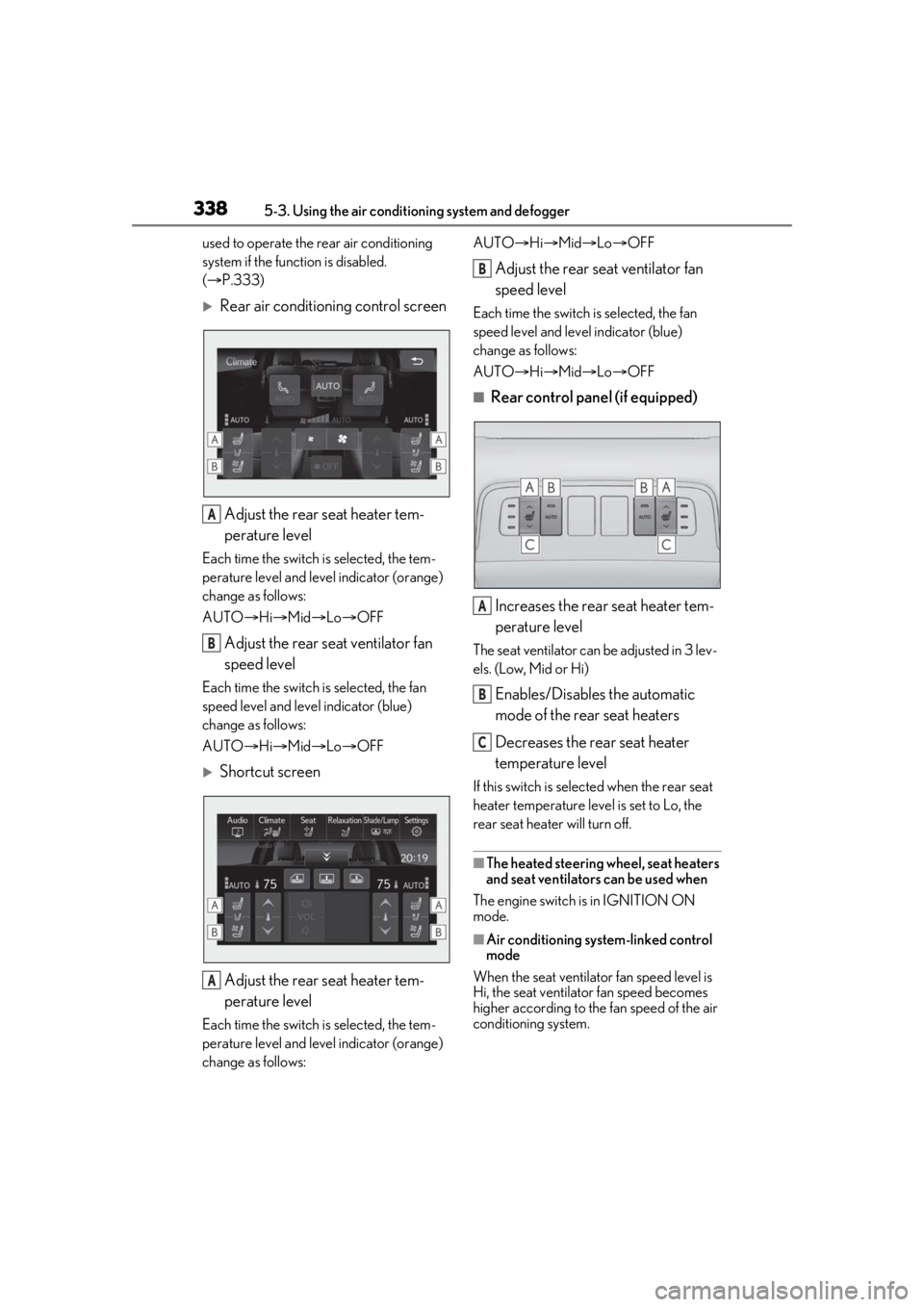
Rear air conditioning control screen
Adjust the rear seat heater tem-
perature level
Each time the switch is selected, the tem-
perature level and leve l indicator (orange)
change as follows:
AUTO Hi Mid Lo OFF
Adjust the rear seat ventilator fan
speed level
Each time the switch is selected, the fan
speed level and leve l indicator (blue)
change as follows:
AUTO Hi Mid Lo OFF
Shortcut screen
Adjust the rear seat heater tem-
perature level
Each time the switch is selected, the tem-
perature level and leve l indicator (orange)
change as follows: AUTO
Hi Mid Lo OFF
Adjust the rear seat ventilator fan
speed level
Each time the switch is selected, the fan
speed level and level indicator (blue)
change as follows:
AUTO Hi Mid Lo OFF
■Rear control panel (if equipped)
Increases the rear seat heater tem-
perature level
The seat ventilator can be adjusted in 3 lev-
els. (Low, Mid or Hi)
Enables/Disables the automatic
mode of the rear seat heaters
Decreases the rear seat heater
temperature level
If this switch is select ed when the rear seat
heater temperature level is set to Lo, the
rear seat heater will turn off.
■The heated steering wheel, seat heaters
and seat ventilators can be used when
The engine switch is in IGNITION ON
mode.
■Air conditioning system-linked control
mode
When the seat ventilator fan speed level is
Hi, the seat ventilato r fan speed becomes
higher according to the fan speed of the air
conditioning system.
A
B
A
B
A
B
C
Page 352 of 520

3525-6. Using the other interior features
5-6.Using the other interior features
The USB charging ports are used to
supply 2.1 A of electricity at 5 V to
external devices.
The USB charging ports are for
charging only. They are not designed
for data transfer or other purposes.
Depending on the external device, it
may not charge properly. Refer to the
manual included with the device
before using a USB charging port.
■Using the USB charging ports
Open the auxiliary boxes lid.
Vehicles without power rear seat
Vehicles with power rear seat
■The USB charging ports can be used
when
The engine switch is in ACCESSORY or IGNITION ON mode.
■Situations in whic
h the USB charging
ports may not operate correctly
●If a device which consumes more than 2.1
A at 5 V is connected
●If a device designed to communicate with
a personal computer, such as a USB
memory device, is connected
●If the connected external device is turned
off (depending on device)
●If the temperature inside the vehicle is
high, such as after the vehicle has been
parked in the sun
■About connected external devices
Depending on the connected external
device, charging may occasionally be sus-
pended and then start again. This is not a
malfunction.
Other interior features
USB charging ports
NOTICE
■To prevent damage to the USB
charging ports
●Do not insert foreign objects into the
ports.
●Do not spill water or other liquids into
the ports.
●When the USB charging ports are not
in use, close the lids. If a foreign object
or liquid enters a port may cause a
short circuit.
●Do not apply excessive force to or
impact the USB charging ports.
●Do not disassemble or modify the USB
charging ports.
■To prevent damage to external
devices
●Do not leave external devices in the
vehicle. The temperature inside the
vehicle may become high, resulting in
damage to an external device.
●Do not push down on or apply unnec-
essary force to an external device or
the cable of an external device while it
is connected.
Page 355 of 520

3555-6. Using the other interior features
5
Interior features
■The power outlet can be used when
●12 V
The engine switch is in ACCESSORY or
IGNITION ON mode.
●120 VAC
The engine switch is in IGNITION ON
mode.
NOTICE
■To avoid damaging the power outlet
Close the power outlet lid when the
power outlet is not in use.
Foreign objects or liquids that enter the
power outlet may cause a short circuit.
■To prevent the fuse from being blown
●12 V
Do not use an accessory that uses more
than 12 V 10 A.
●120 VAC
Do not use a 120 VAC appliance that
requires more than 100 W. If a 120 VAC
appliance that consumes more than 100
W is used, the protection circuit will cut
the power supply.
■To prevent incorrect operation of the
vehicle
When turning the engine switch off,
make sure to disc onnect accessories
designed for charging , such as portable
chargers, power banks, etc. from the
power outlets.
If such an accessory is left connected, the
following may occur:
●The doors cannot be locked using the
smart access system with push-button
start or wireless remote control.
●The opening screen will be displayed
on the multi-information display.
●The interior lights, instrument panel
lights, etc. will illuminate.
■To prevent the battery from being dis-
charged
Do not use the power outlet longer than
necessary when the engine is not run-
ning.
■Appliances that may not operate
properly (120 VAC)
The following 120 VAC appliances may
not operate properly even if their power
consumption is under 100 W.
●Appliances with high initial peak watt-
age
●Measuring devices that process pre-
cise data
●Other appliances that require an
extremely stable power supply
Page 357 of 520

3575-6. Using the other interior features
5
Interior features
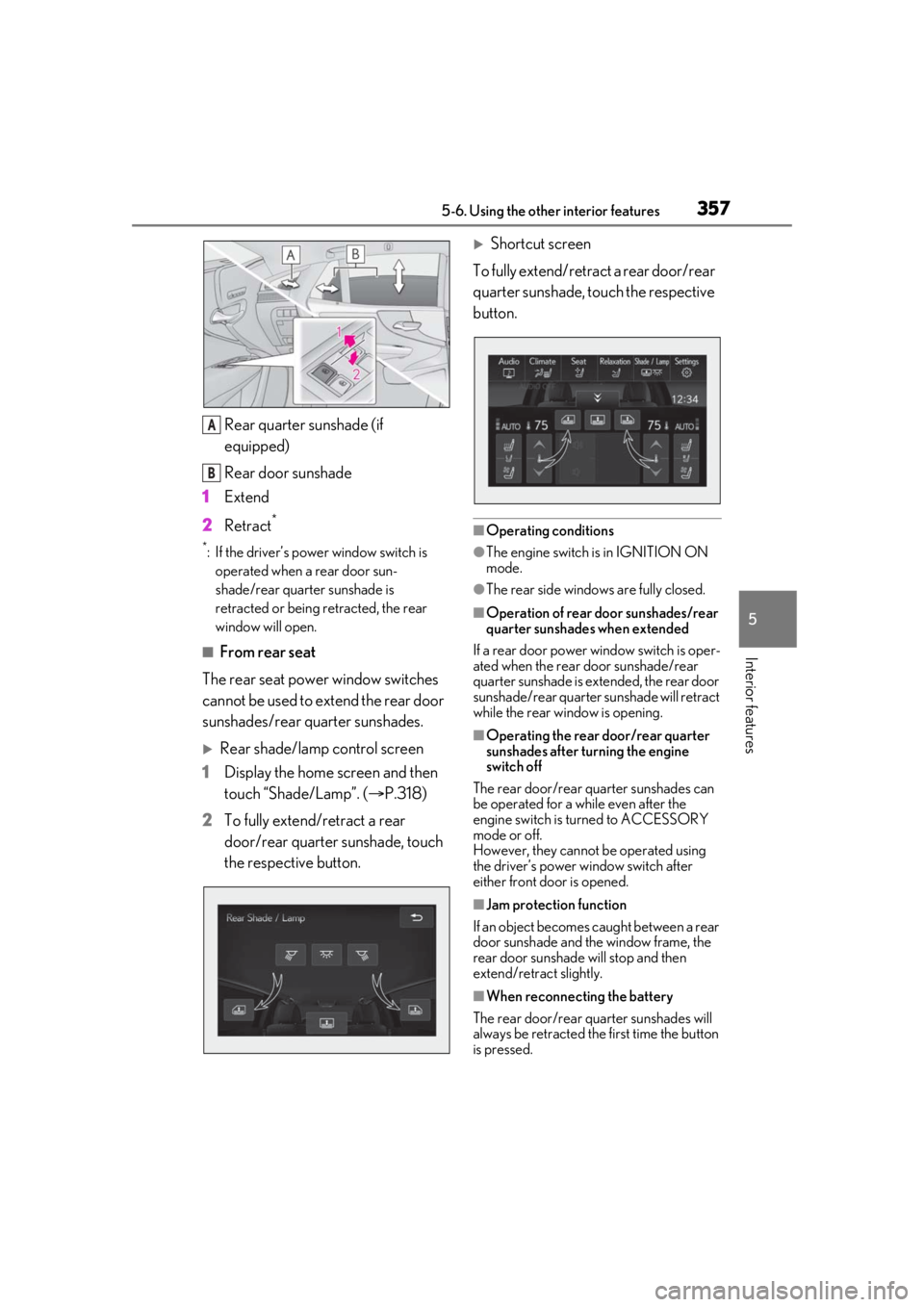
Rear quarter sunshade (if
equipped)
Rear door sunshade
1 Extend
2 Retract
*
*: If the driver’s power window switch is
operated when a rear door sun-
shade/rear quarter sunshade is
retracted or being retracted, the rear
window will open.
■From rear seat
The rear seat power window switches
cannot be used to extend the rear door
sunshades/rear quarter sunshades.
Rear shade/lamp control screen
1 Display the home screen and then
touch “Shade/Lamp”. ( P.318)
2 To fully extend/retract a rear
door/rear quarter sunshade, touch
the respective button.
Shortcut screen
To fully extend/retract a rear door/rear
quarter sunshade, touch the respective
button.
■Operating conditions
●The engine switch is in IGNITION ON
mode.
●The rear side window s are fully closed.
■Operation of rear door sunshades/rear
quarter sunshades when extended
If a rear door power window switch is oper-
ated when the rear door sunshade/rear
quarter sunshade is extended, the rear door
sunshade/rear quarter sunshade will retract
while the rear window is opening.
■Operating the rear door/rear quarter
sunshades after turning the engine
switch off
The rear door/rear quarter sunshades can
be operated for a while even after the
engine switch is turned to ACCESSORY
mode or off.
However, they cannot be operated using
the driver’s power window switch after
either front door is opened.
■Jam protection function
If an object becomes caught between a rear
door sunshade and the window frame, the
rear door sunshade will stop and then
extend/retract slightly.
■When reconnecting the battery
The rear door/rear quarter sunshades will
always be retracted the first time the button
is pressed.
A
B
Page 359 of 520

3595-6. Using the other interior features
5
Interior features
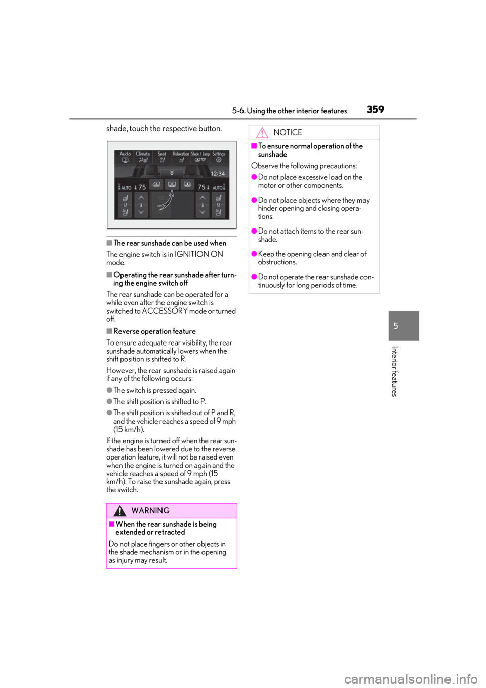
shade, touch the respective button.
■The rear sunshade can be used when
The engine switch is in IGNITION ON
mode.
■Operating the rear sunshade after turn-
ing the engine switch off
The rear sunshade can be operated for a
while even after the engine switch is
switched to ACCESSORY mode or turned
off.
■Reverse operation feature
To ensure adequate rear visibility, the rear
sunshade automatically lowers when the
shift position is shifted to R.
However, the rear suns hade is raised again
if any of the following occurs:
●The switch is pressed again.
●The shift position is shifted to P.
●The shift position is sh ifted out of P and R,
and the vehicle reaches a speed of 9 mph
(15 km/h).
If the engine is turned off when the rear sun-
shade has been lowered due to the reverse
operation feature, it w ill not be raised even
when the engine is turned on again and the
vehicle reaches a speed of 9 mph (15
km/h). To raise the su nshade again, press
the switch.
WARNING
■When the rear sunshade is being
extended or retracted
Do not place fingers or other objects in
the shade mechanism or in the opening
as injury may result.
NOTICE
■To ensure normal operation of the
sunshade
Observe the following precautions:
●Do not place excessive load on the
motor or other components.
●Do not place objects where they may
hinder opening and closing opera-
tions.
●Do not attach items to the rear sun-
shade.
●Keep the opening clean and clear of
obstructions.
●Do not operate the rear sunshade con-
tinuously for long periods of time.
Page 380 of 520

3806-3. Do-it-yourself maintenance
Radiator, con-
denser, inter-
cooler radiator
and intercooler
sub radiator
( P.389)
Tire inflation pres-
sure ( P.406)• Tire pressure gauge
•Compressed air
source
Washer fluid
( P.390)
• Water or washer
fluid containing anti-
freeze (for winter
use)
• Funnel (used only for adding water or
washer fluid)
WARNING
The engine compartment contains many
mechanisms and fluids that may move
suddenly, become hot, or become elec-
trically energized. To avoid death or seri-
ous injury, observe the following
precautions.
■When working on the engine com-
partment
●Keep hands, clothi ng and tools away
from the moving fan and engine drive
belt.
●Be careful not to touch the engine,
radiator, exhaust manifold, etc. right
after driving as they may be hot. Oil
and other fluids may also be hot.
●Do not leave anything that may burn
easily, such as paper and rags, in the
engine compartment.
●Do not smoke, cause sparks or expose
an open flame to fuel. Fuel fumes are
flammable.
ItemsParts and tools■When working near the electric cool-
ing fan or radiator grille
Be sure the engine switch is off.
With the engine switch in IGNITION
ON mode, the electric cooling fan may
automatically start to run if the air condi-
tioning is on and/or the coolant tempera-
ture is high. ( P.389)
■Safety glasses
Wear safety glasses to prevent flying or
falling material, fluid spray, etc. from get-
ting in your eyes.
NOTICE
■If you remove the air cleaner filter
Driving with the air cleaner filter
removed may cause excessive engine
wear due to dirt in the air.
Page 396 of 520

3966-3. Do-it-yourself maintenance
■Routine tire inflation pressure checks
The tire pressure warning system does not
replace routine tire inflation pressure
checks. Make sure to check tire inflation
pressure as part of your routine of daily
vehicle checks.
■Tire inflation pressure
●It may take a few minutes to display the
tire inflation pressure after the engine
switch is turned to IGNITION ON mode.
It may also take a few minutes to display
the tire inflation pres sure after inflation
pressure has been adjusted.
●Tire inflation pressure changes with tem-
perature. The displayed values may also
be different from the values measured
using a tire pressure gauge.
■Situations in which the tire pressure
warning system may not operate prop-
erly
●In the following cases, the tire pressure
warning system may not operate prop-
erly.
• If non-genuine Lexus wheels are used.
• If a tire has been repl aced with a tire that
is not an OE (Original Equipment) tire.
• If a tire has been repl aced with a tire that
is not of the specified size.
• If tire chains, etc. are installed.
• An auxiliary-supported run-flat tire is equipped.
• If a window tint that affects the radio wave signals is installed.
• If there is a lot of snow or ice on the vehi-
cle, particularly around the wheels or
wheel housings.
• If the tire inflation pressure is much higher
than the specified level.
• If wheels not equipped with tire pressure warning valves and tr ansmitter are used.
• If the ID code on the tire pressure warn- ing valves and transmitters is not regis-
tered in the tire pressure warning
computer.
●Performance may be affected in the fol-
lowing situations.
• When driving near a TV tower, electric
power plant, gas station, radio station,
large display, airport or other facility that
generates strong radio waves or electri- cal noise
• When carrying a portable radio, cellular phone, cordless phone or other wireless
communication device
If tire position information is not correctly
displayed due to the radio wave conditions,
the display may be corrected by changing
the location of the vehicle as the radio wave
conditions may change.
●When the vehicle is stopped, the time
taken for the warning to start or turn off
may be longer.
●When the inflation pressure of a tire
drops rapidly, for example when a tire has
burst, the warning may not operate.
■Warning performance of the tire pres-
sure warning system
The warning of the tire pressure warning
system will change in accordance with driv-
ing conditions. For this reason, the system
may give a warning even if the tire pressure
does not reach a low enough level, or if the
pressure is higher than the pressure that
was adjusted to when the system was initial-
ized.