Page 145 of 276

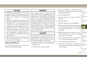
CAUTION!
• Automatic transmissions must be
placed in PARK for recreational towing.
• Manual transmissions must be placed in
gear (not in Neutral) for recreational
towing.
• Before recreational towing, perform the
procedure outlined under “Shifting Into
NEUTRAL (N)” to be certain that the
transfer case is fully in NEUTRAL (N).
Otherwise, internal damage will result.
• Towing this vehicle in violation of the
above requirements can cause severe
transmission and/or transfer case dam-
age. Damage from improper towing is
not covered under the New Vehicle Lim-
ited Warranty.
• Do not use a bumper-mounted clamp-on
tow bar on your vehicle. The bumper
face bar will be damaged.
Shifting Into NEUTRAL (N)
Use the following procedure to prepare your
vehicle for recreational towing.
WARNING!
You or others could be injured or killed if
you leave the vehicle unattended with the
transfer case in the NEUTRAL (N) position
without first fully engaging the parking
brake. The transfer case NEUTRAL (N)
position disengages both the front and rear
driveshafts from the powertrain, and will
allow the vehicle to roll, even if the auto-
matic transmission is in PARK (or manual
transmission is in gear). The parking brake
should always be applied when the driver
is not in the vehicle.
CAUTION!
It is necessary to follow these steps to be
certain that the transfer case is fully in
NEUTRAL (N) before recreational towing
to prevent damage to internal parts.
1. Bring the vehicle to a complete stop on
level ground.
2. Press and hold the brake pedal.3. Shift the automatic transmission into
NEUTRAL or depress the clutch pedal on
a manual transmission.
4. Turn the engine OFF.
5. Shift the transfer case lever into NEU-
TRAL (N).
6. Start the engine.
7. Shift the transmission into REVERSE.
8. Release the brake pedal (and clutch pedal
on manual transmissions) for five seconds
and ensure that there is no vehicle
movement.
9. Repeat steps seven and eight with auto-
matic transmission in DRIVE or manual
transmission in first gear.
10. Turn the engine OFF and leave the igni-
tion in the unlocked ACC position.
11. Firmly apply the parking brake.
12. Shift the transmission into PARK or
place manual transmission in gear (NOT
in NEUTRAL).
143
Page 146 of 276

CAUTION!
Damage to the transmission may occur if
the transmission is shifted into PARK with
the transfer case in NEUTRAL (N) and the
engine running. With the transfer case in
NEUTRAL (N) ensure that the engine is
OFF before shifting the transmission into
PARK.
13. Attach the vehicle to the tow vehicle
using a suitable tow bar.
14. Release the parking brake.
15. Disconnect the negative battery cable,
and secure it away from the negative
battery post.
Shifting Out of NEUTRAL (N)
Use the following procedure to prepare your
vehicle for normal usage.
1. Bring the vehicle to a complete stop,
leaving it connected to the tow vehicle.
2. Firmly apply the parking brake.
3. Reconnect the negative battery cable.
4. Turn the ignition to the LOCK position.
5. Turn the ignition to the ON/RUN position,
but do not start the engine.
6. Press and hold the brake pedal.
7. Shift the transmission into NEUTRAL.8. Shift the transfer case lever to the desired
position.
NOTE:
When shifting the transfer case out of
NEUTRAL (N), the engine should remain
OFF to avoid gear clash.
9. Shift the automatic transmission into
PARK, or place manual transmission in
NEUTRAL.
10. Release the brake pedal.
11. Disconnect vehicle from the tow vehicle.
12. Start the engine.
13. Press and hold the brake pedal.
14. Release the parking brake.
15. Shift the transmission into gear, release
the brake pedal (and clutch pedal on
manual transmissions), and check that
the vehicle operates normally.
STARTING AND OPERATING
144
Page 147 of 276
IN CASE OF EMERGENCY
HAZARD WARNING
FLASHERS................146
BULB REPLACEMENT........146
Replacement Bulbs............146
Bulb Replacement.............147
FUSES...................149
General Information.............150
Totally Integrated Power Module.....150
JACKING AND TIRE
CHANGING................154
Jack/Spare Tire Stowage..........154
Preparations For Jacking.........154
Jacking Instructions............155
Declaration Of Conformance.......157
Jack Usage Precautions..........160
JUMP STARTING............160
Preparations For Jump Start........161
Jump Starting Procedure..........162
IF YOUR ENGINE OVERHEATS . .163GEAR SELECTOR OVERRIDE . . .164
FREEING A STUCK VEHICLE . . .164
TOWING A DISABLED
VEHICLE..................165
Without The Ignition Key..........166
Four–Wheel Drive Models.........166
Tow Eye Usage................167
ENHANCED ACCIDENT RESPONSE
SYSTEM (EARS).............168
EVENT DATA RECORDER
(EDR)....................168
IN CASE OF EMERGENCY
145
Page 148 of 276

HAZARD WARNING
FLASHERS
The Hazard Warning flasher switch is located
on the instrument panel below the climate
controls.
Push the switch to turn on the
Hazard Warning flasher. When the
switch is activated, all directionalturn signals will flash on and off to warn
oncoming traffic of an emergency. Push the
switch a second time to turn off the Hazard
Warning flashers.
This is an emergency warning system and it
should not be used when the vehicle is in
motion. Use it when your vehicle is disabled
and it is creating a safety hazard for other
motorists.When you must leave the vehicle to seek
assistance, the Hazard Warning flashers will
continue to operate even though the ignition
is placed in the OFF position.
NOTE:
With extended use the Hazard Warning flash-
ers may wear down your battery.
BULB REPLACEMENT
Replacement Bulbs
Interior Lights
Bulb Type
Bulb Number
Automatic Transmission Indicator Lamp 658
Courtesy Lights, Under Dash (1)906
Heater Control Lamps (2)194
Rocker Switch Indicator Lamp (Rear Window Defogger) **
Soundbar Dome Lamp912
** Bulbs only available from authorized dealer.
IN CASE OF EMERGENCY
146
Page 149 of 276

Exterior Lights
Bulb Type
Bulb Number
Backup Lamps (2)W16W
Center High-Mounted Stop Lamp (1) L.E.D. (Serviced At Authorized Dealer)
Front Fog Lamps (2)PSX24W
Rear Fog Lamps (2)P27/7W
Front Direction Lamps (2)PY27/7W
Front Side Repeaters/Side Marker Lamps (2) W5W
Headlamps (2)H4
Front Position Lamps (2)12V14W
Stop/Rear Position Lamps (2)P27/7W
Rear Direction Lamps (2)PY27/7W
License Lamp (2)W5W
NOTE:
Numbers refer to commercial bulb types that can be purchased from your local authorized dealer.
Bulb Replacement
NOTE:
Lens fogging can occur under certain atmo-
spheric conditions. This will usually clear as
atmospheric conditions change to allow the
condensation to change back into a vapor.
Turning the lamps on will usually accelerate
the clearing process.
Headlamp
1. Open hood and support using prop rod.
2. Remove the front grille. Turn the retainers
along the top 1/4 turn counterclockwise
and remove.
3. Pull the bottom of the grille away starting
at one side and working toward the other.4. Turn both park and turn signal socket
assemblies 1/4 turn counterclockwise and
remove.
5. Remove the four screws holding the metal
retaining ring.
6. Remove the lamp from the collar.
7. Grasp the bulb and turn 1/4 turn
counterclockwise.
147
Page 150 of 276

8. Pull the bulb from the housing.
9. Push connector locking tab to the unlock
position.
10. Remove connector from bulb.
11. Push connector onto new bulb base, and
push the connector locking tab to the
lock position.
CAUTION!
Do not touch the new bulb with your fin-
gers. Oil contamination will severely
shorten bulb life. If the bulb comes in
contact with any oily surface, clean the
bulb with rubbing alcohol.
12. Reinstall bulb housing. Rotate the bulb
1/4 turn clockwise.
Front Park/Turn Signal
1. Remove the front grille. Turn the retainers
along the top 1/4 turn counterclockwise
and remove.
2. Pull the bottom of the grille away starting
at one side and working toward the other.3. Turn the socket assembly 1/4 turn coun-
terclockwise and remove from housing.
Pull the bulb straight from the socket to
replace.
Front Side Marker
1. Reach under the front fender flare and
locate the front side marker socket.
2. Turn the socket assembly counterclock-
wise 1/3 turn and remove it from the
housing. Pull the bulb straight from the
socket to replace.
Front Fog Lamp
1. Reach under the vehicle to access the
back of the front fog lamp.
2. Disconnect the wire harness connector
from the front fog lamp connector
receptacle.
3. Firmly grasp the bulb by the two latch
features and squeeze them together to
unlock the bulb from the back of the front
fog lamp housing.4. Pull the bulb straight out from the keyed
opening in the housing and then connect
the replacement bulb.
CAUTION!
Do not touch the new bulb with your fin-
gers. Oil contamination will severely
shorten bulb life. If the bulb comes in
contact with any oily surface, clean the
bulb with rubbing alcohol.
Rear Fog Lamp
1. Reach under the vehicle to access the
back of the rear fog lamp.
2. Turn the socket assembly counterclock-
wise 1/4 turn and remove it from the
housing. Pull the bulb straight from the
socket to replace.IN CASE OF EMERGENCY
148
Page 151 of 276

Rear Tail, Stop, Turn Signal, And Backup
Lamp
1. Remove the two inboard screws attaching
the tail light housing to the body.DO NOT
REMOVE THE OUTBOARD SCREWS AT ANY
TIME.
2. Separate the housing from the body by
pushing the lamp inboard while pulling
the lamp away from the body.3. Rotate the appropriate socket 1/4 turn
counterclockwise, then remove it from the
housing.
4. Pull the bulb straight from the socket to
replace.
Center High-Mounted Stop Lamp (CHMSL)
The stop lamp is mounted on a bracket that
extends upward from the tailgate behind the
spare tire. If service is needed, obtain the
LED/Cover Assembly from your local autho-
rized dealer.
1. Remove the spare tire.
2. Remove the four screws holding the lens/
cover in place on the spare tire carrier.
3. Disconnect the wire harness from the
back of the LED cover.
FUSES
WARNING!
• When replacing a blown fuse, always use
an appropriate replacement fuse with
the same amp rating as the original fuse.
Never replace a fuse with another fuse of
higher amp rating. Never replace a
blown fuse with metal wires or any other
material. Failure to use proper fuses may
result in serious personal injury, fire
and/or property damage.
• Before replacing a fuse, make sure that
the ignition is off and that all the other
services are switched off and/or disen-
gaged.
• If the replaced fuse blows again, contact
an authorized dealer.
• If a general protection fuse for safety
systems (air bag system, braking sys-
tem), power unit systems (engine sys-
tem, gearbox system) or steering system
blows, contact an authorized dealer.
Inboard Screw Location
149
Page 152 of 276
General Information
The fuses protect electrical systems against
excessive current.
When a device does not work, you must check
the fuse element inside the blade fuse for a
break/melt.
Also, please be aware that when using power
outlets for extended periods of time with the
engine off may result in vehicle battery dis-
charge.
Totally Integrated Power Module
The Totally Integrated Power Module is lo-
cated in the engine compartment near the
battery. This center contains cartridge fuses,
mini fuses, and relays. A label that identifies
each component is printed on the inside of
the cover.
Cavity Cartridge Fuse Mini Fuse Description
J1 – – –
J2 30 Amp Pink – Transfer Case Module
J3 – – –
J4 25 Amp Clear – Driver Door Node
J5 25 Amp Clear – Passenger Door Node
J6 40 Amp Green – Anti-Lock Brake System (ABS) Pump/Stability Control
System
J7 30 Amp Pink – Anti-Lock Brake System (ABS) Valve/Stability Control
System
Totally Integrated Power Module
IN CASE OF EMERGENCY
150