Page 442 of 482
7-63
7
Maintenance
Engine compartment fuse panel
Fuse NameFuse RatingProtected Component
FUEL PUMP20AE/R Junction Block (Fuel Pump Relay)
VACUUM
PUMP120AVacuum Pump
TCU115ATCM
COOLING
FAN240AE/R Junction Block (C/Fan1 Low Relay, C/Fan2 Hi Relay) (G4NH)
B+140AIGPM ((Fuse - BRAKE SWITCH, PDM1, PDM3, MODULE1, DOOR LOCK), Leak Current Autocut Device)
DCT140ATCM
DCT240ATCM
B/ALARM
HORN15AE/R Junction Block (B/ALARM Horn Relay)
ABS140AESC Module, ABS Control Module, Multipurpose Check Connector
ABS230AESC Module, ABS Control Module
[G4FJ] : 1.6 T-GDI
[G4NH] : 2.0 MPI
Page 443 of 482
7-64
Maintenance
Fuse NameFuse RatingProtected Component
SENSOR210A
G4FJ : Canister Close Valve, Oil Control Valve #1/#2, RCV Control Solenoid Valve,
Purge Control Solenoid Valve, E/R Junction Block (C/FAN2 HI Relay)
G4NH : Canister Close Valve, Oil Control Valve #1/#2/#3, Electronic Thermostat, Variable Intake Solenoid
Valve, Purge Control Solenoid Valve, E/R Junction Block (C/FAN 1 Low Relay, C/FAN 2 HI Relay)
ECU210AECM (G4FJ)
ECU120AECM/PCM
INJECTOR15AInjector #1/#2/#3/#4 (G4NH)
SENSOR115AOxygen Sensor (Up/Down)
IGN COIL20AIgnition Coil #1/#2/#3/#4
ECU315AECM/PCM
A/C10AA/CON COMP Relay (G4NH)
ECU510AECM/PCM
VACUUM
PUMP215AVacuum Pump (G4FJ)
Engine compartment fuse panel
[G4FJ] : 1.6 T-GDI
[G4NH] : 2.0 MPI
Page 444 of 482
7-65
7
Maintenance
Fuse NameFuse RatingProtected Component
ABS310AABS Control Module, ESC Module, Multipurpose Check Connector
TCU215ATransmission Range Switch(A/T), TCM (With DCT)
SENSOR310AE/R Junction Block (F/PUMP Relay)
ECU415AECM/PCM
HORN15AHorn Relay
Engine compartment fuse panel
[G4FJ] : 1.6 T-GDI
[G4NH] : 2.0 MPI
Page 445 of 482
7-66
Maintenance
Engine compartment fuse panel
(Battery terminal cover)
(for Nu 2.0 MPI)
Inside the fuse/relay box cover, you
can find the fuse/relay label describ-
ing fuse/relay names and ratings.
Information
Not all fuse panel descriptions in this
manual may be applicable to your
vehicle; the information is accurate at
the time of printing. When you inspect
the fuse panel in your vehicle, refer to
the fuse panel label.
i
OJS078055L
OPD076065
After checking the fuse panel in the engine compartment, securely
install the cover. If it is not securely latched, electrical failure may occur
from water contact.
NOTICE
Page 453 of 482
7-74
Maintenance
[A] : Stop/Tail lamp, [B] : Turn signal lamp
6. Remove the bulb from the socket by
pressing it in and rotating it counter-
clockwise until the tabs on the bulb
align with the slots in the socket.
Pull the bulb out of the socket.7. Insert a new bulb by inserting it
into the socket and rotating it until
it locks into place.
8. Install the socket into the assem-
bly by aligning the tabs on the
socket with the slots in the assem-
bly. Push the socket into the
assembly and turn the socket
clockwise.
9. Reinstall the lamp assembly to the
body of the vehicle.
Tail lamp and backup lamp
1. Turn off the engine.
2. Open the tailgate.
3. Remove the service cover using a
flat-blade screwdriver.
OJS078034OJS078035L
■Type A
OJS078036L
■Type B
Page 454 of 482
![HYUNDAI VELOSTER 2021 Owners Manual 7-75
7
Maintenance
[A] : Tail lamp, [B] : Backup lamp
4. Remove the socket from the
assembly by turning the socket
counterclockwise until the tabs on
the socket align with the slots on
the assembly.5. HYUNDAI VELOSTER 2021 Owners Manual 7-75
7
Maintenance
[A] : Tail lamp, [B] : Backup lamp
4. Remove the socket from the
assembly by turning the socket
counterclockwise until the tabs on
the socket align with the slots on
the assembly.5.](/manual-img/35/41165/w960_41165-453.png)
7-75
7
Maintenance
[A] : Tail lamp, [B] : Backup lamp
4. Remove the socket from the
assembly by turning the socket
counterclockwise until the tabs on
the socket align with the slots on
the assembly.5. Remove the bulb from the socket
by pressing it in and rotating it
counterclockwise until the tabs on
the bulb align with the slots in the
socket. Pull the bulb out of the
socket.
6. Insert a new bulb by inserting it
into the socket and rotating it until
it locks into place.
7. Install the socket into the assem-
bly by aligning the tabs on the
socket with the slots in the assem-
bly. Push the socket into the
assembly and turn the socket
clockwise.
8. Reinstall the lamp assembly to the
body of the vehicle.
Side marker
1. Turn off the engine.
2. Open the liftgate.
3. Remove the service cover using a
flat-blade screwdriver.
4. Remove the rear combination light
assembly from the body of the
vehicle.
5. Remove the socket from the
assembly by turning the socket
counterclock wise until the tabs on
the socket align with the slots on
the assembly.
OJS078037L
■Type A
OJS078038L
■Type B
OJS078071N
Page 458 of 482

7-79
7
Maintenance
High-pressure washing
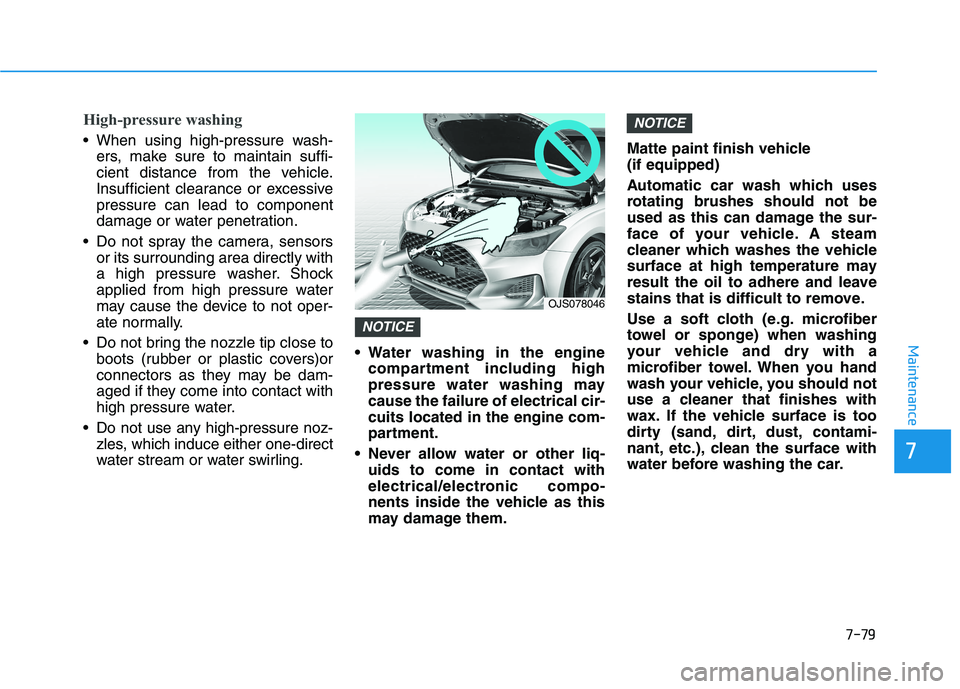
When using high-pressure wash-
ers, make sure to maintain suffi-
cient distance from the vehicle.
Insufficient clearance or excessive
pressure can lead to component
damage or water penetration.
Do not spray the camera, sensors
or its surrounding area directly with
a high pressure washer. Shock
applied from high pressure water
may cause the device to not oper-
ate normally.
Do not bring the nozzle tip close to
boots (rubber or plastic covers)or
connectors as they may be dam-
aged if they come into contact with
high pressure water.
Do not use any high-pressure noz-
zles, which induce either one-direct
water stream or water swirling. Water washing in the engine
compartment including high
pressure water washing may
cause the failure of electrical cir-
cuits located in the engine com-
partment.
Never allow water or other liq-
uids to come in contact with
electrical/electronic compo-
nents inside the vehicle as this
may damage them.Matte paint finish vehicle
(if equipped)
Automatic car wash which uses
rotating brushes should not be
used as this can damage the sur-
face of your vehicle. A steam
cleaner which washes the vehicle
surface at high temperature may
result the oil to adhere and leave
stains that is difficult to remove.
Use a soft cloth (e.g. microfiber
towel or sponge) when washing
your vehicle and dry with a
microfiber towel. When you hand
wash your vehicle, you should not
use a cleaner that finishes with
wax. If the vehicle surface is too
dirty (sand, dirt, dust, contami-
nant, etc.), clean the surface with
water before washing the car.
NOTICE
NOTICE
OJS078046
Page 466 of 482

7-87
7
Maintenance
Canister
Fuel vapors generated inside the fuel
tank are absorbed and stored in the
onboard canister. When the engine is
running, the fuel vapors absorbed in
the canister are drawn into the surge
tank through the purge control sole-
noid valve.
Purge Control Solenoid Valve
(PCSV)
The purge control solenoid valve is
controlled by the Engine Control
Module (ECM); when the engine
coolant temperature is low during
idling, the PCSV closes so that evap-
orated fuel is not taken into the
engine. After the engine warms-up
during ordinary driving, the PCSV
opens to introduce evaporated fuel to
the engine.
3. Exhaust Emission Control
System
The Exhaust Emission Control
System is a highly effective system
which controls exhaust emissions
while maintaining good vehicle per-
formance.
When the engine starts or fails to
start, excessive attempts to restart
the engine may cause damage to the
emission system.
Engine exhaust (carbon monox-
ide) precautions
Carbon monoxide can be present
with other exhaust fumes. If you
smell exhaust fumes of any kind in
your vehicle, drive with all the win-
dows fully open. Have your vehicle
checked and repaired immediately.
Engine exhaust gases contain
carbon monoxide (CO). Though
colorless and odorless, it is
dangerous and could be lethal if
inhaled. Follow the instructions
on this page to avoid CO poi-
soning.
WARNING