Page 588 of 636
Maintenance
9-38
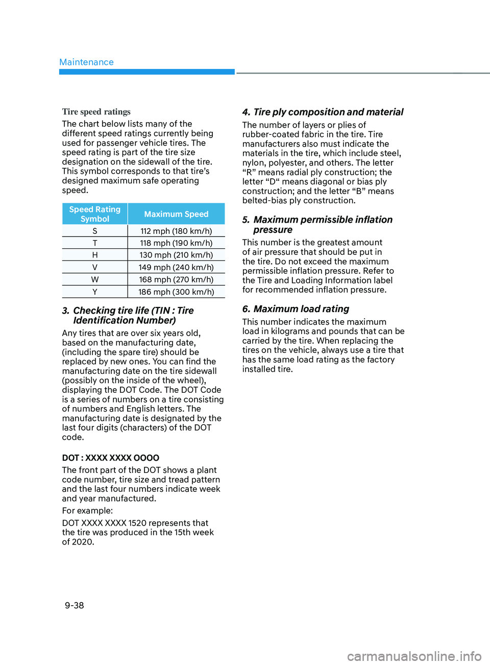
Tire speed ratings
The chart below lists many of the
different speed ratings currently being
used for passenger vehicle tires. The
speed rating is part of the tire size
designation on the sidewall of the tire.
This symbol corresponds to that tire’s
designed maximum safe operating
speed.
Speed Rating Symbol Maximum Speed
S 112 mph (180 km/h)
T 118 mph (190 km/h)
H 130 mph (210 km/h)
V 149 mph (240 km/h)
W 168 mph (270 km/h) Y 186 mph (300 km/h)
3. Checking tire lif e (TIN : Tire
Identification Number)
Any tires that are over six years old,
based on the manufacturing date,
(including the spare tire) should be
replaced by new ones. You can find the
manufacturing date on the tire sidewall
(possibly on the inside of the wheel),
displaying the DOT Code. The DOT Code
is a series of numbers on a tire consisting
of numbers and English letters. The
manufacturing date is designated by the
last four digits (characters) of the DOT
code.
DOT : XXXX XXXX OOOO
The front part of the DOT shows a plant
code number, tire size and tread pattern
and the last four numbers indicate week
and year manufactured.
For example:
DOT XXXX XXXX 1520 represents that
the tire was produced in the 15th week
of 2020.
4. Tire ply composition and material
The number of layers or plies of
rubber-coated fabric in the tire. Tire
manufacturers also must indicate the
materials in the tire, which include steel,
nylon, polyester, and others. The letter
“R” means radial ply construction; the
letter “D“ means diagonal or bias ply
construction; and the letter “B” means
belted-bias ply construction.
5. Maximum permissible inflation
pr essure
This number is the greatest amount
of air pressure that should be put in
the tire. Do not exceed the maximum
permissible inflation pressure. Refer to
the Tire and Loading Information label
for recommended inflation pressure.
6. Maximum load rating
This number indicates the maximum
load in kilograms and pounds that can be
carried by the tire. When replacing the
tires on the vehicle, always use a tire that
has the same load rating as the factory
installed tire.
Page 590 of 636
Maintenance
9-40
WARNING
The temperature grade for this tire is
established for a tire that is properly
inflated and not overloaded. Excessive
speed, under-inflation, over-inflation,
or excessive loading, either separately
or in combination, can cause heat build-
up and possible sudden tire failure.
This may cause loss of vehicle control
resulting in an accident.
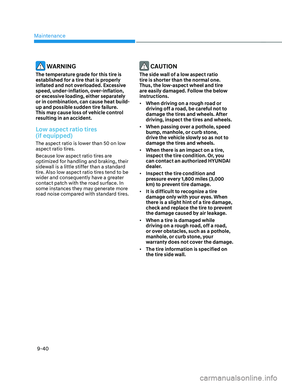
Low aspect ratio tires
(if equipped)
The aspect ratio is lower than 50 on low
aspect ratio tires.
Because low aspect ratio tires are
optimized for handling and braking, their
sidewall is a little stiffer than a standard
tire. Also low aspect ratio tires tend to be
wider and consequently have a greater
contact patch with the road surface. In
some instances they may generate more
road noise compared with standard tires.
CAUTION
The side wall of a low aspect ratio
tire is shorter than the normal one.
Thus, the low-aspect wheel and tire
are easily damaged. Follow the below
instructions.
• When driving on a rough road or
driving off a road, be careful not to
damage the tires and wheels. After
driving, inspect the tires and wheels.
• When passing over a pothole, speed
bump, manhole, or curb stone,
drive the vehicle slowly so as not to
damage the tires and wheels.
• When there is an impact on a tire,
inspect the tire condition. Or, you
can contact an authorized HYUNDAI
dealer.
• Inspect the tire condition and
pressure every 1,800 miles (3,000
km) to prevent tire damage.
• It is difficult to recognize a tire
damage only with your eyes. When
there is a slight hint of a tire damage,
check and replace the tire to prevent
the damage caused by air leakage.
• When a tire is damaged while
driving on a rough road, off a road,
or over obstacles, such as a pothole,
manhole, or curb stone, your
warranty does not cover the damage.
• The tire information is specified on
the tire side wall.
Page 592 of 636
Maintenance
9-42
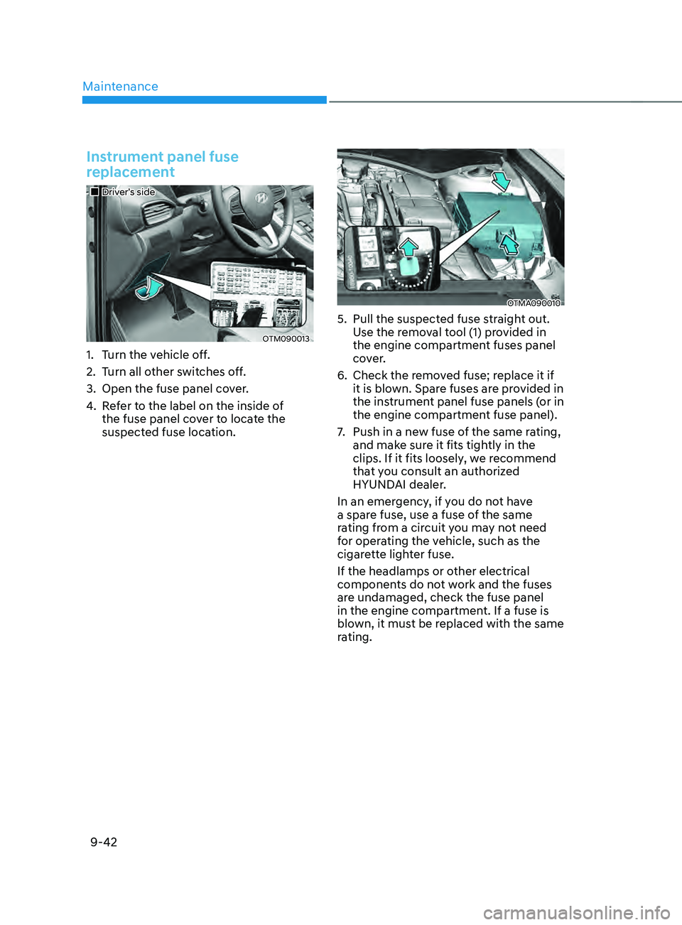
Instrument panel fuse
replacement
„„Driver’s side
OTM090013
1. Turn the vehicle off.
2.
Turn all o
ther switches off.
3.
Open the fuse panel cov
er.
4.
Re
fer to the label on the inside of
the fuse panel cover to locate the
suspected fuse location.
OTMA090010
5. Pull the suspected fuse s traight out.
Use the removal tool (1) provided in
the engine compartment fuses panel
cover.
6.
Check the remo
ved fuse; replace it if
it is blown. Spare fuses are provided in
the instrument panel fuse panels (or in
the engine compartment fuse panel).
7.
Push in a new fuse o
f the same rating,
and make sure it fits tightly in the
clips. If it fits loosely, we recommend
that you consult an authorized
HYUNDAI dealer.
In an emergency, if you do not have
a spare fuse, use a fuse of the same
rating from a circuit you may not need
for operating the vehicle, such as the
cigarette lighter fuse.
If the headlamps or other electrical
components do not work and the fuses
are undamaged, check the fuse panel
in the engine compartment. If a fuse is
blown, it must be replaced with the same
rating.
Page 594 of 636
Maintenance
9-44
Fuse/relay panel description
Instrument panel fuse panel
OTM090019
Inside the fuse/relay box cover, you can
find the fuse/relay label describing fuse/
relay names and ratings.
Information
Not all fuse panel descriptions in this
manual may be applicable to your vehicle;
the information is accurate at the time of
printing. When you inspect the fuse box on
your vehicle, refer to the fuse box label.
OTMA090026
Page 596 of 636
Maintenance
9-46
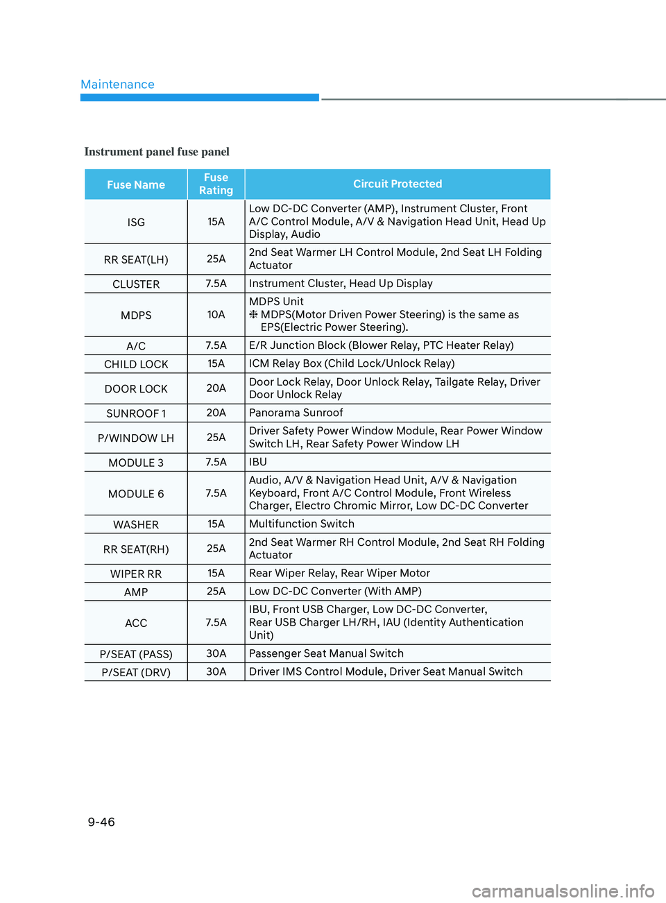
Instrument panel fuse panel
Fuse NameFuse
Rating Circuit Protected
ISG 15ALow DC-DC Converter (AMP), Instrument Cluster, Front
A/C Control Module, A/V & Navigation Head Unit, Head Up
Display, Audio
RR SEAT(LH) 25A2nd Seat Warmer LH Control Module, 2nd Seat LH Folding
Actuator
CLUSTER 7.5A Instrument Cluster, Head Up Display
MDPS 10AMDPS Unit
❈
MDPS(Mo
tor Driven Power Steering) is the same as
EPS(Electric Power Steering).
A/C 7.5A E/R Junction Block (Blower Relay, PTC Heater Relay)
CHILD LOCK 15A ICM Relay Box (Child Lock/Unlock Relay)
DOOR LOCK 20ADoor Lock Relay, Door Unlock Relay, Tailgate Relay, Driver
Door Unlock Relay
SUNROOF 1 20A
Panorama Sunroof
P/WINDOW LH 25ADriver Safety Power Window Module, Rear Power Window
Switch LH, Rear Safety Power Window LH
MODULE 3 7.5A IBU
MODULE 6 7.5AAudio, A/V & Navigation Head Unit, A/V & Navigation
Keyboard, Front A/C Control Module, Front Wireless
Charger, Electro Chromic Mirror, Low DC-DC Converter
WASHER 15A Multifunction Switch
RR SEAT(RH) 25A2nd Seat Warmer RH Control Module, 2nd Seat RH Folding
Actuator
WIPER RR 15A Rear Wiper Relay, Rear Wiper Motor
AMP 25A Low DC-DC Converter (With AMP)
ACC 7.5AIBU, Front USB Charger, Low DC-DC Converter,
Rear USB Charger LH/RH, IAU (Identity Authentication
Unit)
P/SEAT (PASS) 30A
Passenger Seat Manual Switch
P/SEAT (DRV) 30A
Driver IMS Control Module, Driver Seat Manual Switch
Page 598 of 636
![HYUNDAI SANTA FE CALLIGRAPHY 2021 Owners Manual Maintenance
9-48
Engine compartment fuse panel (Engine room junction block)
Type Fuse NameFuse
Rating Circuit Protected
MULTI
FUSE 1 (10P) COOLING FAN1
80A
[BLDC 600W] Cooling Fan Controller
COOLIN HYUNDAI SANTA FE CALLIGRAPHY 2021 Owners Manual Maintenance
9-48
Engine compartment fuse panel (Engine room junction block)
Type Fuse NameFuse
Rating Circuit Protected
MULTI
FUSE 1 (10P) COOLING FAN1
80A
[BLDC 600W] Cooling Fan Controller
COOLIN](/manual-img/35/56181/w960_56181-597.png)
Maintenance
9-48
Engine compartment fuse panel (Engine room junction block)
Type Fuse NameFuse
Rating Circuit Protected
MULTI
FUSE 1 (10P) COOLING FAN1
80A
[BLDC 600W] Cooling Fan Controller
COOLING FAN2 60A
[BLDC 400W] Cooling Fan Controller
B+4 50AICU Junction Block (Fuse - MODULE8,
SUNROOF1, AMP, P/WINDOW RH, S/HEATER
DRV/PASS)
B+2 50AICU Junction Block (IPS 8 SPOC+/IPS 10/IPS 11/
IPS 13/IPS 14/IPS 15)
B+3 50AICU Junction Block (Fuse - E-SHIFTER1, P/
SEAT (DRV, P/SEAT (PASS), P/WINDOW LH, RR
SEAT(LH))
BLOWER 40A
Blower Relay
IG2 40A
Start Relay, PCB Block (PDM (IG2) Relay)
ABS 2 30A
ESC Module
MULTI
FUSE 2 (10P) MDPS
100A MDPS Unit
ABS 3 60A
ESC Module
B+6 60A
PCB Block (B+)
DCT 60A
TCM
E-CVVT1 50A
PCB Block (E-CVVT Relay)
REAR HEATED 40A
Rear Heated Relay
INVERTER 40A
AC Inverter Module
E-SHIFTER 1 40A
SCU
FUSE HEATED
MIRROR 10A
Rear Heated Relay, Driver/Passenger Outside
Mirror, Front A/C Control Module
E-CVVT3 20A
PCM, PCB Block (E-CVVT Relay)
E-CVVT2 20A
PCM, PCB Block (E-CVVT Relay)
A/C2 10A
Blower Relay, Front A/C Control Module
VACUUM PUMP2 10A
ESC Module, Vacuum Pump Relay, Vacuum Pump
B+5 50AICU Junction Block (Fuse - DOOR LOCK,
IBU1, IBU2, BRAKE SWITCH, CHILD LOCK, RR
SEAT(RH), SUNROOF2)
EOP2 60A
[G4KP] Electronic Oil Pump
Page 600 of 636
Maintenance
9-50
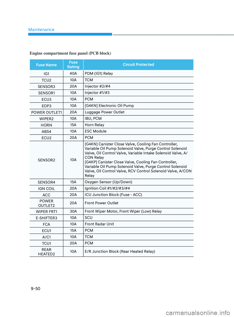
Engine compartment fuse panel (PCB block)
Fuse NameFuse
Rating Circuit Protected
IG1 40A
PDM (IG1) Relay
TCU2 10A
TCM
SENSOR3 20A
Injector #2/#4
SENSOR1 10A
Injector #1/#3
ECU3 10A
PCM
EOP3 10A
[G4KN] Electronic Oil Pump
POWER OUTLET1 20A
Luggage Power Outlet
WIPER2 10A
IBU, PCM
HORN 15A Horn Relay
ABS4 10A
ESC Module
ECU2 20A
PCM
SENSOR2 10A[G4KN] Canister Close Valve, Cooling Fan Controller,
Variable Oil Pump Solenoid Valve, Purge Control Solenoid
Valve, Oil Control Valve, Variable Intake Solenoid Valve, A/
CON Relay
[G4KP] Canister Close Valve, Cooling Fan Controller,
Variable Oil Pump Solenoid Valve, Purge Control Solenoid
Valve, Oil Control Valve, RCV Control Solenoid Valve, A/CON
Relay
SENSOR4 15A Oxygen Sensor (Up/Down)
IGN COIL 20A
Ignition Coil #1/#2/#3/#4
ACC 20A
ICU Junction Block (Fuse - ACC)
POWER
OUTLET2 20A
Front Power Outlet
WIPER FRT1 30A
Front Wiper Motor, Front Wiper (Low) Relay
E-SHIFTER3 10A
SCU
FCA 10A
Front Radar Unit
ECU1 15A PCM
A/C1 10A
TCM
TCU1 20A
PCM
REAR
HEATED2 10A
E/R Junction Block (Rear Heated Relay)
Page 602 of 636
Maintenance
9-52
Information
• A normally functioning lamp may
flicker momentarily to stabilize the
vehicle’s electrical control system.
However, if the lamp goes out after
flickering momentarily, or continues to
flicker, we recommend the system be
checked by an authorized HYUNDAI
dealer.
• The position lamp may not turn on
when the position lamp switch is turned
on, but the position lamp and headlamp
switch may turn on when the headlamp
switch is turned on. This may be caused
by network failure or vehicle electrical
control system malfunction. If this
occurs, we recommend the system be
checked by an authorized HYUNDAI
dealer.
Information
The headlamp aiming should be adjusted
after an accident or after the headlamp
assembly is reinstalled.
Information
Traffic Change (For Europe)
The low beam light distribution is
asymmetric. If you go abroad to a country
with opposite traffic direction, this
asymmetric part will dazzle oncoming car
driver. To prevent dazzle, ECE regulation
demand several technical solutions (ex.
automatic change system, adhesive
sheet, down aiming). This headlamps are
designed not to dazzle opposite drivers. So,
you need not change your headlamps in a
country with opposite traffic direction.
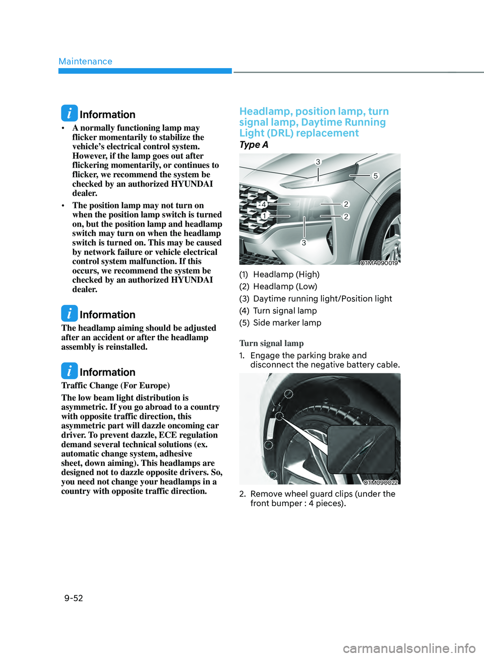
Headlamp, position lamp, turn
signal lamp, Daytime Running
Light (DRL) replacement
Type A
OTMA090019
(1) Headlamp (High)
(2)
Headlamp (L
ow)
(3)
Daytime running ligh
t/Position light
(4)
Turn signal lamp
(5)
Side marker lamp
T
urn signal lamp
1.
Engage the parking br
ake and
disconnect the negative battery cable.
OTM090022
2. Remove wheel guard clips (under the
fr ont bumper : 4 pieces).