Page 566 of 636
Maintenance
9-16
ENGINE OIL
Brake discs, pads, calipers and
rotors
Check the pads, the disc, and the rotor
for any excessive wear-out. Inspect
calipers for any fluid leakage.
For more information on checking the
pads or lining wear limit, refer to the
HYUNDAI web site.
(http://service.hyundai-motor.com)
Propeller shaft
Check the propeller shaft, boots, clamps,
rubber couplings and center-bearing
rubber for cracks, deterioration, or
damage. Replace any damaged parts
and if necessary, repack the grease.
Suspension mounting bolts
Check the suspension connections for
looseness or damage. Retighten to the
specified torque.
Steering gear box, linkage &
boots/lower arm ball joint
With the vehicle stopped and the engine
off, check for excessive free-play in the
steering wheel. Check the linkage for
bends or damage. Check the dust boots
and ball joints for deterioration, cracks,
or damage.
Replace any damaged parts.
Drive shafts and boots
Check the drive shafts, boots and clamps
for cracks, deterioration, or damage.
Replace any damaged parts and, if
necessary, repack the grease.
Air conditioning refrigerant
Check the air conditioning lines and
connections for leakage and damage.
Checking the engine oil level
Gasoline engine
1. Follow all of the oil manufacturer’s
precautions.
2.
Be sure the v
ehicle is on the level
ground in P (Park) with the parking
brake set and the wheels blocked.
3.
Turn the engine on and allo
w the
engine to reach normal operating
temperature.
4.
Turn the engine o
ff and wait about 15
minutes for the oil to return to the oil
pan.
5.
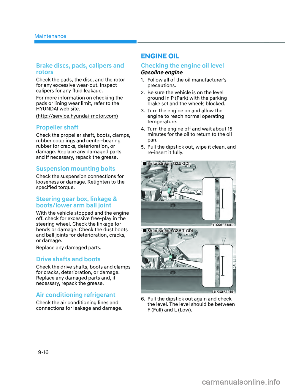
Pull the dipstick out, wipe it clean, and
r
e-insert it fully.
„„Smartstream G2.5 GDI
OTMA090002
„„Smartstream G2.5 T-GDI
OTMA090016
6. Pull the dipstick out again and check
the le vel. The level should be between
F (Full) and L (Low).
Page 567 of 636
09
9-17
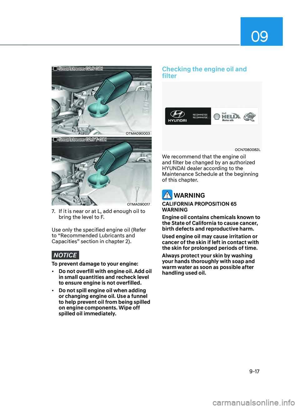
„„Smartstream G2.5 GDI
OTMA090003
„„Smartstream G2.5 T-GDI
OTMA090017
7. If it is near or at L, add enough oil to
bring the level to F.
Use only the specified engine oil (Refer
to “Recommended Lubricants and
Capacities” section in chapter 2).
NOTICE
To prevent damage to your engine:
• Do not overfill with engine oil. Add oil
in small quantities and recheck level
to ensure engine is not overfilled.
• Do not spill engine oil when adding
or changing engine oil. Use a funnel
to help prevent oil from being spilled
on engine components. Wipe off
spilled oil immediately.
Checking the engine oil and
filter
OCN7080082L
We recommend that the engine oil
and filter be changed by an authorized
HYUNDAI dealer according to the
Maintenance Schedule at the beginning
of this chapter.
WARNING
CALIFORNIA PROPOSITION 65
WARNING
Engine oil contains chemicals known to
the State of California to cause cancer,
birth defects and reproductive harm.
Used engine oil may cause irritation or
cancer of the skin if left in contact with
the skin for prolonged periods of time.
Always protect your skin by washing
your hands thoroughly with soap and
warm water as soon as possible after
handling used oil.
Page 571 of 636

09
9-21
Checking the brake fluid level
OTMA090005
Check the fluid level in the reservoir
periodically. The fluid level should be
between MAX and MIN marks on the side
of the reservoir.
Before removing the reservoir cap and
adding brake fluid, clean the area around
the reservoir cap thoroughly to prevent
brake fluid contamination.
If the level is low, add the specified
brake fluid to the MAX level. The level
will fall with accumulated mileage. This
is a normal condition associated with
the wear of the brake linings. If the fluid
level is excessively low, we recommend
that the brake system be checked by an
authorized HYUNDAI dealer.
WARNING
If the brake system requires frequent
additions of fluid this could indicate
a leak in the brake system. We
recommend that the vehicle be
inspected by an authorized HYUNDAI
dealer.
WARNING
Do not allow brake fluid to come in
contact with your eyes. If brake fluid
comes in contact with your eyes, flush
your eyes with clean water for at least
15 minutes and get immediate medical
attention.
NOTICE
• Do not allow brake fluid to contact
the vehicle’s body paint, as paint
damage will result.
• Brake fluid, which has been exposed
to open air for an extended time
should NEVER be used as its quality
cannot be guaranteed. It should be
disposed of properly.
• Do not use the wrong kind of brake
fluid. A few drops of mineral based
oil, such as engine oil, in your brake
system can damage brake system
parts.
Information
Use only the specified brake fluid (refer
to “Recommended Lubricants and
Capacities” section in chapter 2).
BRAKE FLUID
Page 573 of 636
09
9-23
Filter replacement
OTMA090007
The air cleaner filter can be cleaned for
inspection using compressed air. Do not
attempt to wash or to rinse it, as water
will damage the filter. If soiled, the air
cleaner filter must be replaced.
OTMA090008
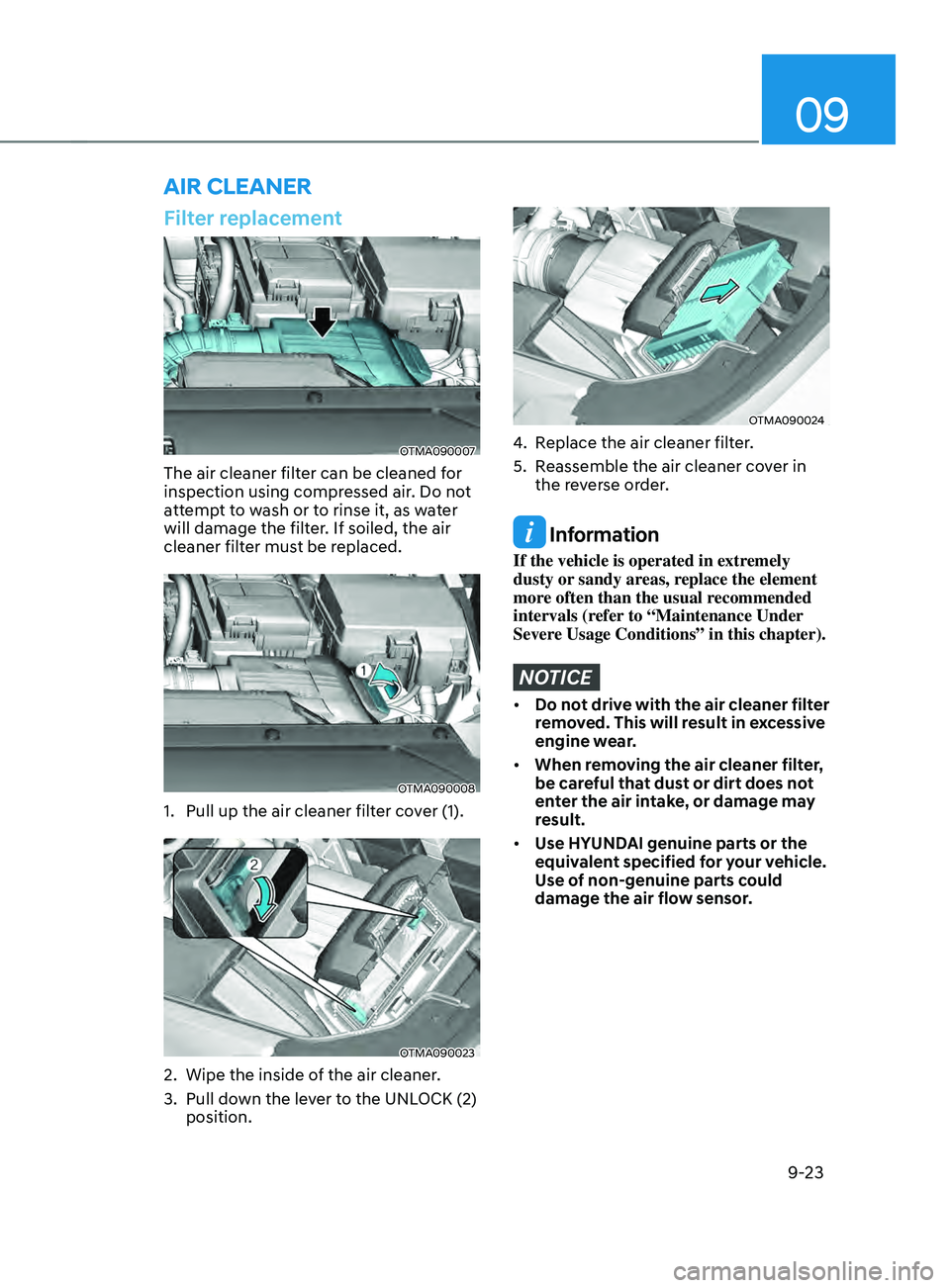
1. Pull up the air cleaner filter cover (1).
OTMA090023
2. Wipe the inside of the air cleaner .
3.
Pull down the le
ver to the UNLOCK (2)
position.
OTMA090024
4. Replace the air cleaner filter.
5.
Reassemble the air cleaner co
ver in
the reverse order.
Information
If the vehicle is operated in extremely
dusty or sandy areas, replace the element
more often than the usual recommended
intervals (refer to “Maintenance Under
Severe Usage Conditions” in this chapter).
NOTICE
• Do not drive with the air cleaner filter
removed. This will result in excessive
engine wear.
• When removing the air cleaner filter,
be careful that dust or dirt does not
enter the air intake, or damage may
result.
• Use HYUNDAI genuine parts or the
equivalent specified for your vehicle.
Use of non-genuine parts could
damage the air flow sensor.
AIR CLEANER
Page 580 of 636
Maintenance
9-30
Battery capacity label
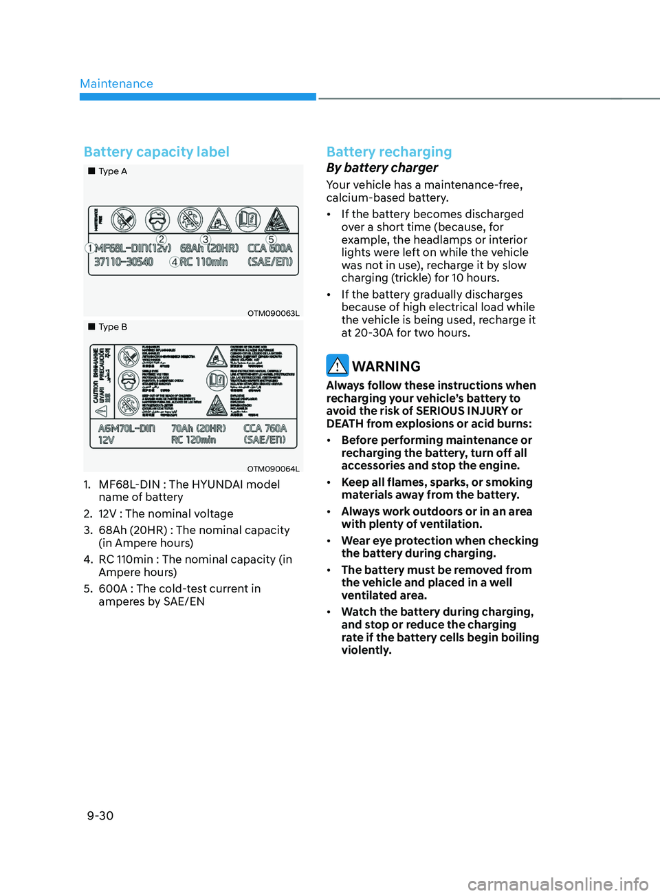
„„Type A
OTM090063L
„„Type B
OTM090064L
1. MF68L-DIN : The HYUNDAI model
name of battery
2.
12V : The nominal voltage
3.
68Ah (20HR) : The nominal capacity
(in Ampere hour
s)
4.
RC 110min : The nominal capacity (in
Amper
e hours)
5.
600A : The cold-
test current in
amperes by SAE/EN
Battery recharging
By battery charger
Your vehicle has a maintenance-free,
calcium-based battery.
• If the battery becomes discharged
over a short time (because, for
example, the headlamps or interior
lights were left on while the vehicle
was not in use), recharge it by slow
charging (trickle) for 10 hours.
• If the battery gradually discharges
because of high electrical load while
the vehicle is being used, recharge it
at 20-30A for two hours.
WARNING
Always follow these instructions when
recharging your vehicle’s battery to
avoid the risk of SERIOUS INJURY or
DEATH from explosions or acid burns:
• Before performing maintenance or
recharging the battery, turn off all
accessories and stop the engine.
• Keep all flames, sparks, or smoking
materials away from the battery.
• Always work outdoors or in an area
with plenty of ventilation.
• Wear eye protection when checking
the battery during charging.
• The battery must be removed from
the vehicle and placed in a well
ventilated area.
• Watch the battery during charging,
and stop or reduce the charging
rate if the battery cells begin boiling
violently.
Page 591 of 636
09
9-41
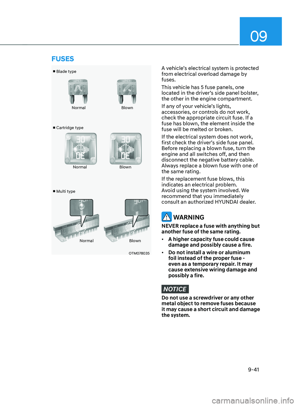
■ Blade type
■ Cartridge type
■ Multi type Normal
Blown
Normal Blown
Normal Blown
OTM078035
A vehicle’s electrical system is protected
from electrical overload damage by
fuses.
This vehicle has 5 fuse panels, one
located in the driver’s side panel bolster,
the other in the engine compartment.
If any of your vehicle’s lights,
accessories, or controls do not work,
check the appropriate circuit fuse. If a
fuse has blown, the element inside the
fuse will be melted or broken.
If the electrical system does not work,
first check the driver’s side fuse panel.
Before replacing a blown fuse, turn the
engine and all switches off, and then
disconnect the negative battery cable.
Always replace a blown fuse with one of
the same rating.
If the replacement fuse blows, this
indicates an electrical problem.
Avoid using the system involved. We
recommend that you immediately
consult an authorized HYUNDAI dealer.
WARNING
NEVER replace a fuse with anything but
another fuse of the same rating.
• A higher capacity fuse could cause
damage and possibly cause a fire.
• Do not install a wire or aluminum
foil instead of the proper fuse -
even as a temporary repair. It may
cause extensive wiring damage and
possibly a fire.
NOTICE
Do not use a screwdriver or any other
metal object to remove fuses because
it may cause a short circuit and damage
the system.
FUSES
Page 598 of 636
![HYUNDAI SANTA FE CALLIGRAPHY 2021 Owners Manual Maintenance
9-48
Engine compartment fuse panel (Engine room junction block)
Type Fuse NameFuse
Rating Circuit Protected
MULTI
FUSE 1 (10P) COOLING FAN1
80A
[BLDC 600W] Cooling Fan Controller
COOLIN HYUNDAI SANTA FE CALLIGRAPHY 2021 Owners Manual Maintenance
9-48
Engine compartment fuse panel (Engine room junction block)
Type Fuse NameFuse
Rating Circuit Protected
MULTI
FUSE 1 (10P) COOLING FAN1
80A
[BLDC 600W] Cooling Fan Controller
COOLIN](/manual-img/35/56181/w960_56181-597.png)
Maintenance
9-48
Engine compartment fuse panel (Engine room junction block)
Type Fuse NameFuse
Rating Circuit Protected
MULTI
FUSE 1 (10P) COOLING FAN1
80A
[BLDC 600W] Cooling Fan Controller
COOLING FAN2 60A
[BLDC 400W] Cooling Fan Controller
B+4 50AICU Junction Block (Fuse - MODULE8,
SUNROOF1, AMP, P/WINDOW RH, S/HEATER
DRV/PASS)
B+2 50AICU Junction Block (IPS 8 SPOC+/IPS 10/IPS 11/
IPS 13/IPS 14/IPS 15)
B+3 50AICU Junction Block (Fuse - E-SHIFTER1, P/
SEAT (DRV, P/SEAT (PASS), P/WINDOW LH, RR
SEAT(LH))
BLOWER 40A
Blower Relay
IG2 40A
Start Relay, PCB Block (PDM (IG2) Relay)
ABS 2 30A
ESC Module
MULTI
FUSE 2 (10P) MDPS
100A MDPS Unit
ABS 3 60A
ESC Module
B+6 60A
PCB Block (B+)
DCT 60A
TCM
E-CVVT1 50A
PCB Block (E-CVVT Relay)
REAR HEATED 40A
Rear Heated Relay
INVERTER 40A
AC Inverter Module
E-SHIFTER 1 40A
SCU
FUSE HEATED
MIRROR 10A
Rear Heated Relay, Driver/Passenger Outside
Mirror, Front A/C Control Module
E-CVVT3 20A
PCM, PCB Block (E-CVVT Relay)
E-CVVT2 20A
PCM, PCB Block (E-CVVT Relay)
A/C2 10A
Blower Relay, Front A/C Control Module
VACUUM PUMP2 10A
ESC Module, Vacuum Pump Relay, Vacuum Pump
B+5 50AICU Junction Block (Fuse - DOOR LOCK,
IBU1, IBU2, BRAKE SWITCH, CHILD LOCK, RR
SEAT(RH), SUNROOF2)
EOP2 60A
[G4KP] Electronic Oil Pump
Page 600 of 636
Maintenance
9-50
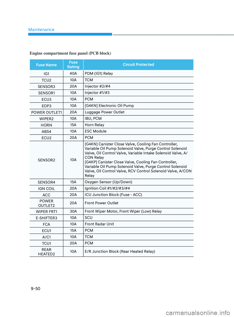
Engine compartment fuse panel (PCB block)
Fuse NameFuse
Rating Circuit Protected
IG1 40A
PDM (IG1) Relay
TCU2 10A
TCM
SENSOR3 20A
Injector #2/#4
SENSOR1 10A
Injector #1/#3
ECU3 10A
PCM
EOP3 10A
[G4KN] Electronic Oil Pump
POWER OUTLET1 20A
Luggage Power Outlet
WIPER2 10A
IBU, PCM
HORN 15A Horn Relay
ABS4 10A
ESC Module
ECU2 20A
PCM
SENSOR2 10A[G4KN] Canister Close Valve, Cooling Fan Controller,
Variable Oil Pump Solenoid Valve, Purge Control Solenoid
Valve, Oil Control Valve, Variable Intake Solenoid Valve, A/
CON Relay
[G4KP] Canister Close Valve, Cooling Fan Controller,
Variable Oil Pump Solenoid Valve, Purge Control Solenoid
Valve, Oil Control Valve, RCV Control Solenoid Valve, A/CON
Relay
SENSOR4 15A Oxygen Sensor (Up/Down)
IGN COIL 20A
Ignition Coil #1/#2/#3/#4
ACC 20A
ICU Junction Block (Fuse - ACC)
POWER
OUTLET2 20A
Front Power Outlet
WIPER FRT1 30A
Front Wiper Motor, Front Wiper (Low) Relay
E-SHIFTER3 10A
SCU
FCA 10A
Front Radar Unit
ECU1 15A PCM
A/C1 10A
TCM
TCU1 20A
PCM
REAR
HEATED2 10A
E/R Junction Block (Rear Heated Relay)