2021 FORD F650/750 air filter
[x] Cancel search: air filterPage 219 of 390
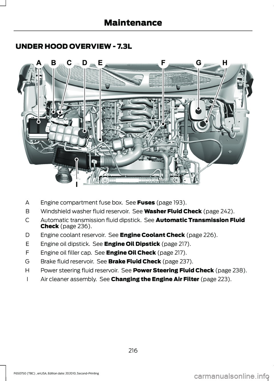
UNDER HOOD OVERVIEW - 7.3L
Engine compartment fuse box. See Fuses (page 193).
A
Windshield washer fluid reservoir. See
Washer Fluid Check (page 242).
B
Automatic transmission fluid dipstick. See
Automatic Transmission Fluid
Check (page 236).
C
Engine coolant reservoir. See
Engine Coolant Check (page 226).
D
Engine oil dipstick. See
Engine Oil Dipstick (page 217).
E
Engine oil filler cap. See
Engine Oil Check (page 217).
F
Brake fluid reservoir. See
Brake Fluid Check (page 237).
G
Power steering fluid reservoir. See
Power Steering Fluid Check (page 238).
H
Air cleaner assembly. See
Changing the Engine Air Filter (page 223).
I
216
F650750 (TBC) , enUSA, Edition date: 202010, Second-Printing MaintenanceE314523
Page 224 of 390
From the main menu scroll to:
Action and Description
Message
Press the down arrow
button, then from this menu
scroll to the following
message.
Truck Info
Press the OK button.
Mainten-
ance
Monitor
Press the down arrow
button, then from this menu
scroll to the following
message.
Oil Life:
xxx%
Press the
OK button.
Oil Life
Press and hold the
OK
button until the instrument
cluster displays the
following message.
Oil Life
Hold OK to
Reset
Oil Life: 100%
When the oil change indic-
ator resets, the instrument
cluster displays 100%.
Repeat the process if the oil
change indicator does not
reset.
CHANGING THE ENGINE AIR
FILTER - 6.7L DIESEL
Air Filter Restriction Gauge WARNING:
To reduce the risk of
vehicle damage and personal burn
injuries, do not start your engine with the
air cleaner removed and do not remove
it while the engine is running. Note:
Operating your vehicle in heavy
snowfall or extreme rain conditions may
allow excessive amounts of snow or water
into the air intake system. This could plug
or soak the air filter and cause the engine to
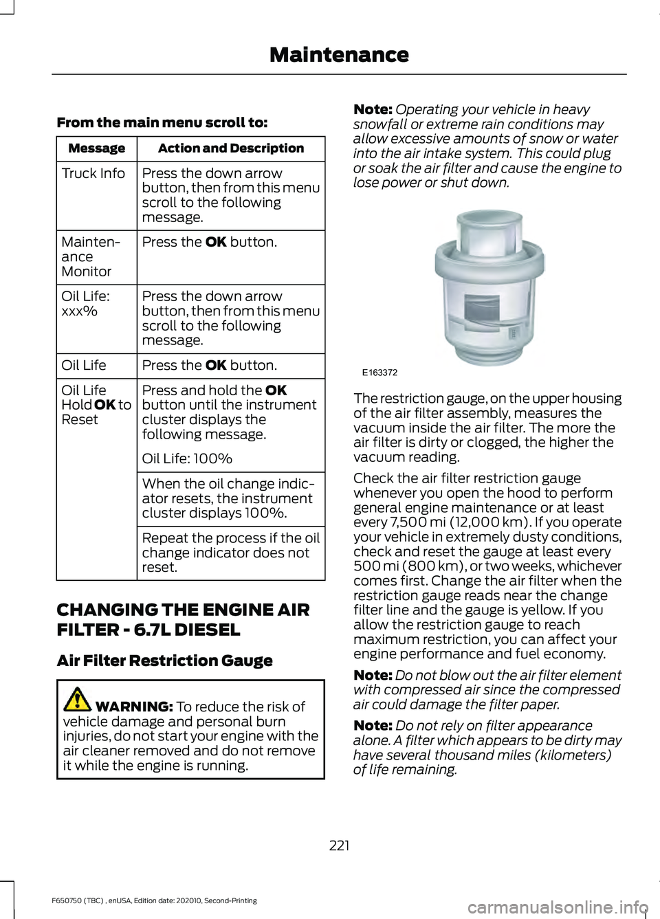
lose power or shut down. The restriction gauge, on the upper housing
of the air filter assembly, measures the
vacuum inside the air filter. The more the
air filter is dirty or clogged, the higher the
vacuum reading.
Check the air filter restriction gauge
whenever you open the hood to perform
general engine maintenance or at least
every 7,500 mi (12,000 km). If you operate
your vehicle in extremely dusty conditions,
check and reset the gauge at least every
500 mi (800 km), or two weeks, whichever
comes first. Change the air filter when the
restriction gauge reads near the change
filter line and the gauge is yellow. If you
allow the restriction gauge to reach
maximum restriction, you can affect your
engine performance and fuel economy.
Note:
Do not blow out the air filter element
with compressed air since the compressed
air could damage the filter paper.
Note: Do not rely on filter appearance
alone. A filter which appears to be dirty may
have several thousand miles (kilometers)
of life remaining.
221
F650750 (TBC) , enUSA, Edition date: 202010, Second-Printing MaintenanceE163372
Page 225 of 390
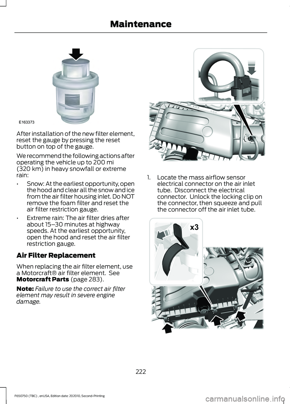
After installation of the new filter element,
reset the gauge by pressing the reset
button on top of the gauge.
We recommend the following actions after
operating the vehicle up to 200 mi
(320 km) in heavy snowfall or extreme
rain:
• Snow: At the earliest opportunity, open
the hood and clear all the snow and ice
from the air filter housing inlet. Do NOT
remove the foam filter and reset the
air filter restriction gauge.
• Extreme rain: The air filter dries after
about 15– 30 minutes at highway
speeds. At the earliest opportunity,
open the hood and reset the air filter
restriction gauge.
Air Filter Replacement
When replacing the air filter element, use
a Motorcraft® air filter element. See
Motorcraft Parts
(page 283).
Note: Failure to use the correct air filter
element may result in severe engine
damage. 1. Locate the mass airflow sensor
electrical connector on the air inlet
tube. Disconnect the electrical
connector. Unlock the locking clip on
the connector, then squeeze and pull
the connector off the air inlet tube. 222
F650750 (TBC) , enUSA, Edition date: 202010, Second-Printing MaintenanceE163373 E317651 x3E317652
Page 226 of 390
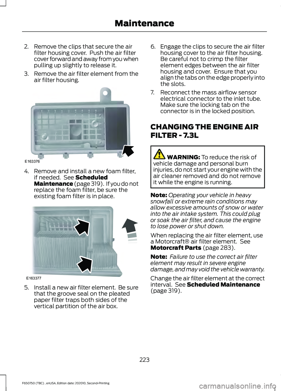
2. Remove the clips that secure the air
filter housing cover. Push the air filter
cover forward and away from you when
pulling up slightly to release it.
3. Remove the air filter element from the
air filter housing. 4. Remove and install a new foam filter,
if needed. See Scheduled
Maintenance (page 319). If you do not
replace the foam filter, be sure the
existing foam filter is in place. 5.
Install a new air filter element. Be sure
that the groove seal on the pleated
paper filter traps both sides of the
vertical partition of the air box. 6. Engage the clips to secure the air filter
housing cover to the air filter housing.
Be careful not to crimp the filter
element edges between the air filter
housing and cover. Ensure that you
align the tabs on the edge properly into
the slots.
7. Reconnect the mass airflow sensor electrical connector to the inlet tube.
Make sure the locking tab on the
connector is in the locked position.
CHANGING THE ENGINE AIR
FILTER - 7.3L WARNING:
To reduce the risk of
vehicle damage and personal burn
injuries, do not start your engine with the
air cleaner removed and do not remove
it while the engine is running.
Note: Operating your vehicle in heavy
snowfall or extreme rain conditions may
allow excessive amounts of snow or water
into the air intake system. This could plug
or soak the air filter, and cause the engine
to lose power or shut down.
When replacing the air filter element, use
a Motorcraft® air filter element. See
Motorcraft Parts
(page 283).
Note: Failure to use the correct air filter
element may result in severe engine
damage, and may void the vehicle warranty.
Change the air filter element at the correct
interval. See
Scheduled Maintenance
(page 319).
223
F650750 (TBC) , enUSA, Edition date: 202010, Second-Printing MaintenanceE163376 E163377
Page 228 of 390
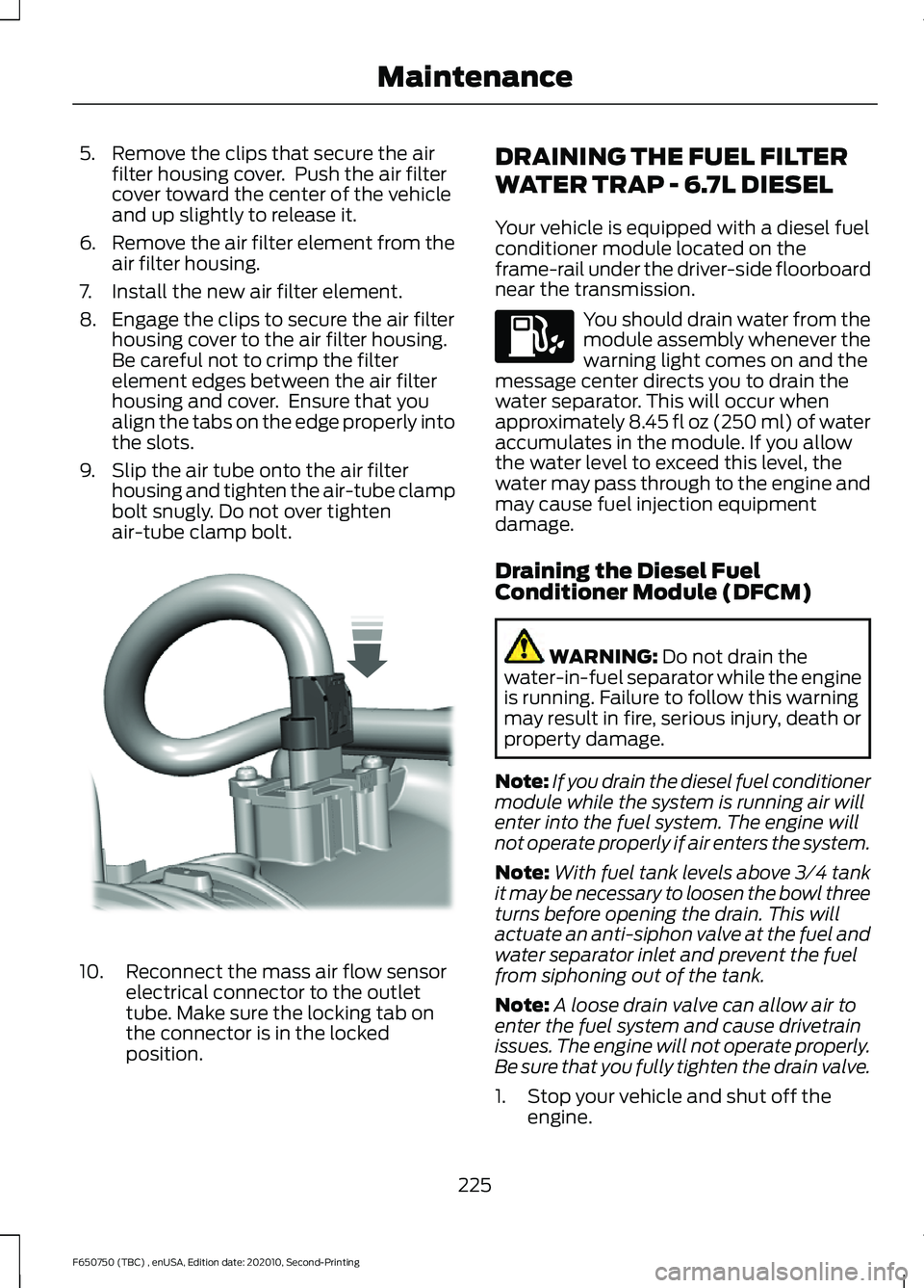
5. Remove the clips that secure the air
filter housing cover. Push the air filter
cover toward the center of the vehicle
and up slightly to release it.
6. Remove the air filter element from the
air filter housing.
7. Install the new air filter element.
8. Engage the clips to secure the air filter housing cover to the air filter housing.
Be careful not to crimp the filter
element edges between the air filter
housing and cover. Ensure that you
align the tabs on the edge properly into
the slots.
9. Slip the air tube onto the air filter housing and tighten the air-tube clamp
bolt snugly. Do not over tighten
air-tube clamp bolt. 10. Reconnect the mass air flow sensor
electrical connector to the outlet
tube. Make sure the locking tab on
the connector is in the locked
position. DRAINING THE FUEL FILTER
WATER TRAP - 6.7L DIESEL
Your vehicle is equipped with a diesel fuel
conditioner module located on the
frame-rail under the driver-side floorboard
near the transmission. You should drain water from the
module assembly whenever the
warning light comes on and the
message center directs you to drain the
water separator. This will occur when
approximately 8.45 fl oz (250 ml) of water
accumulates in the module. If you allow
the water level to exceed this level, the
water may pass through to the engine and
may cause fuel injection equipment
damage.
Draining the Diesel Fuel
Conditioner Module (DFCM) WARNING: Do not drain the
water-in-fuel separator while the engine
is running. Failure to follow this warning
may result in fire, serious injury, death or
property damage.
Note: If you drain the diesel fuel conditioner
module while the system is running air will
enter into the fuel system. The engine will
not operate properly if air enters the system.
Note: With fuel tank levels above 3⁄4 tank
it may be necessary to loosen the bowl three
turns before opening the drain. This will
actuate an anti-siphon valve at the fuel and
water separator inlet and prevent the fuel
from siphoning out of the tank.
Note: A loose drain valve can allow air to
enter the fuel system and cause drivetrain
issues. The engine will not operate properly.
Be sure that you fully tighten the drain valve.
1. Stop your vehicle and shut off the engine.
225
F650750 (TBC) , enUSA, Edition date: 202010, Second-Printing MaintenanceE317619
Page 229 of 390
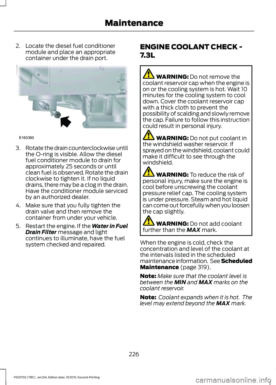
2. Locate the diesel fuel conditioner
module and place an appropriate
container under the drain port. 3.
Rotate the drain counterclockwise until
the O-ring is visible. Allow the diesel
fuel conditioner module to drain for
approximately 25 seconds or until
clean fuel is observed. Rotate the drain
clockwise to tighten it. If no liquid
drains, there may be a clog in the drain.
Have the conditioner module serviced
by an authorized dealer.
4. Make sure that you fully tighten the drain valve and then remove the
container from under your vehicle.
5. Restart the engine. If the Water in Fuel
Drain Filter message and light
continues to illuminate, have the fuel
system checked and repaired. ENGINE COOLANT CHECK -
7.3L WARNING:
Do not remove the
coolant reservoir cap when the engine is
on or the cooling system is hot. Wait 10
minutes for the cooling system to cool
down. Cover the coolant reservoir cap
with a thick cloth to prevent the
possibility of scalding and slowly remove
the cap. Failure to follow this instruction
could result in personal injury. WARNING:
Do not put coolant in
the windshield washer reservoir. If
sprayed on the windshield, coolant could
make it difficult to see through the
windshield. WARNING:
To reduce the risk of
personal injury, make sure the engine is
cool before unscrewing the coolant
pressure relief cap. The cooling system
is under pressure. Steam and hot liquid
can come out forcefully when you loosen
the cap slightly. WARNING:
Do not add coolant
further than the MAX mark.
When the engine is cold, check the
concentration and level of the coolant at
the intervals listed in the scheduled
maintenance information. See Scheduled
Maintenance
(page 319).
Note: Make sure that the coolant level is
between the
MIN and MAX marks on the
coolant reservoir.
Note: Coolant expands when it is hot. The
level may extend beyond the
MAX mark.
226
F650750 (TBC) , enUSA, Edition date: 202010, Second-Printing MaintenanceE163360
Page 245 of 390
WASHER FLUID CHECK
WARNING: If you operate your
vehicle in temperatures below 40°F
(5°C), use washer fluid with antifreeze
protection. Failure to use washer fluid
with antifreeze protection in cold
weather could result in impaired
windshield vision and increase the risk
of injury or accident.
Add fluid to fill the reservoir if the level is
low. Only use a washer fluid that meets
Ford specifications. See
Capacities and
Specifications (page 281).
State or local regulations on volatile
organic compounds may restrict the use
of methanol, a common windshield washer
antifreeze additive. Washer fluids
containing non-methanol antifreeze
agents should be used only if they provide
cold weather protection without damaging
the vehicle ’s paint finish, wiper blades or
washer system.
FUEL FILTER - 7.3L
Your vehicle is equipped with a lifetime
fuel filter that is integrated with the fuel
tank. Regular maintenance or replacement
is not needed.
CHECKING THE WIPER
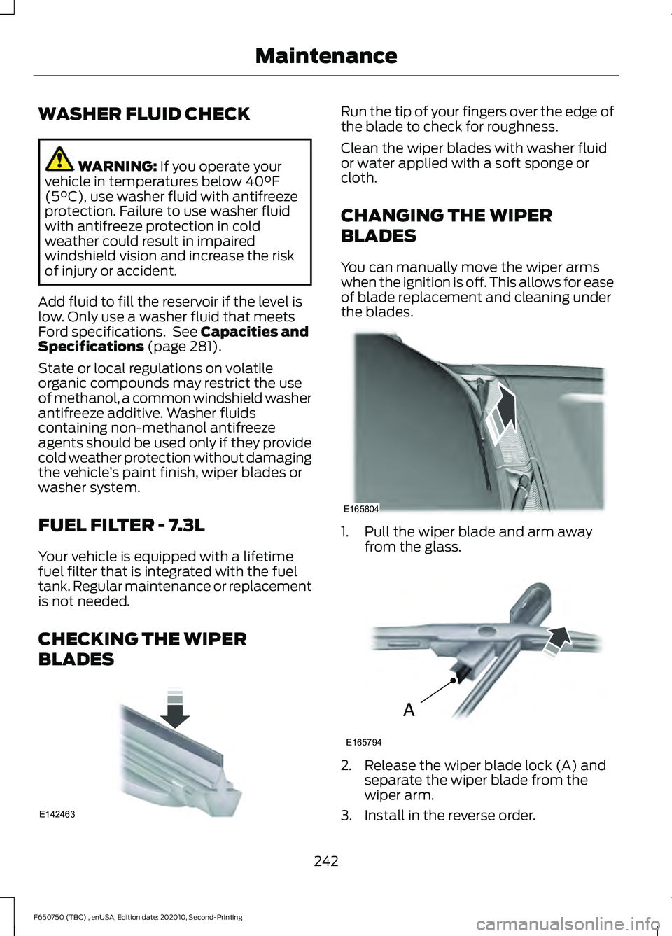
BLADES Run the tip of your fingers over the edge of
the blade to check for roughness.
Clean the wiper blades with washer fluid
or water applied with a soft sponge or
cloth.
CHANGING THE WIPER
BLADES
You can manually move the wiper arms
when the ignition is off. This allows for ease
of blade replacement and cleaning under
the blades.
1. Pull the wiper blade and arm away
from the glass. 2. Release the wiper blade lock (A) and
separate the wiper blade from the
wiper arm.
3. Install in the reverse order.
242
F650750 (TBC) , enUSA, Edition date: 202010, Second-Printing MaintenanceE142463 E165804 A
E165794
Page 249 of 390
2.
Install the lower portion of the housing
on the top portion. Tighten by hand
until you feel a strong resistance.
Continue to tighten with a 32mm
socket wrench until the mechanical
stop on the bottom meets the top.
3. Connect the electrical connector.
4. Tighten the drain plug, turn it clockwise
until it stops and you feel a strong
resistance. Do not use any tools to
tighten the drain plug.
5. Switch the ignition on for 30 seconds and then switch the ignition off.
Repeat this operation six times in a row
to purge any trapped air from the fuel
system.
Engine-mounted Fuel Filter
Although the fuel system is not fully
pressurized when the vehicle is off, some
residual pressure may remain in the fuel
system since it can take some time for the
pressure to completely bleed off.
Therefore, we recommend you place an
absorbent cloth below the filter connectors
to absorb any fuel that may drain.
The engine-mounted fuel filter is a plastic
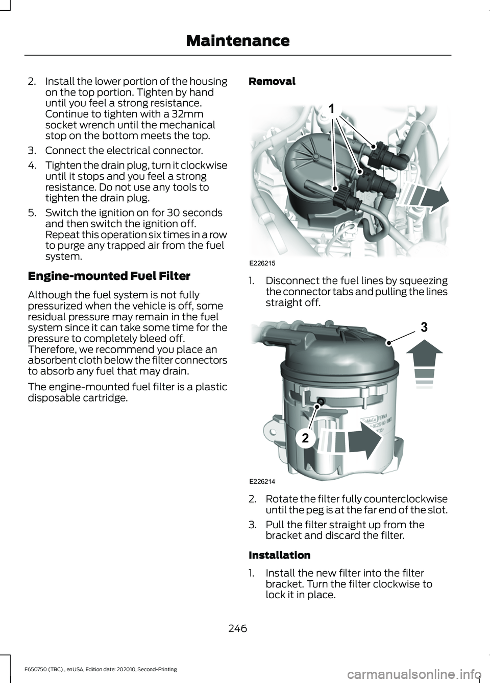
disposable cartridge. Removal 1.
Disconnect the fuel lines by squeezing
the connector tabs and pulling the lines
straight off. 2.
Rotate the filter fully counterclockwise
until the peg is at the far end of the slot.
3. Pull the filter straight up from the bracket and discard the filter.
Installation
1. Install the new filter into the filter bracket. Turn the filter clockwise to
lock it in place.
246
F650750 (TBC) , enUSA, Edition date: 202010, Second-Printing MaintenanceE226215
1 E226214
2
3