2021 CHRYSLER 300 steering wheel
[x] Cancel search: steering wheelPage 111 of 268
STARTING AND OPERATING 109
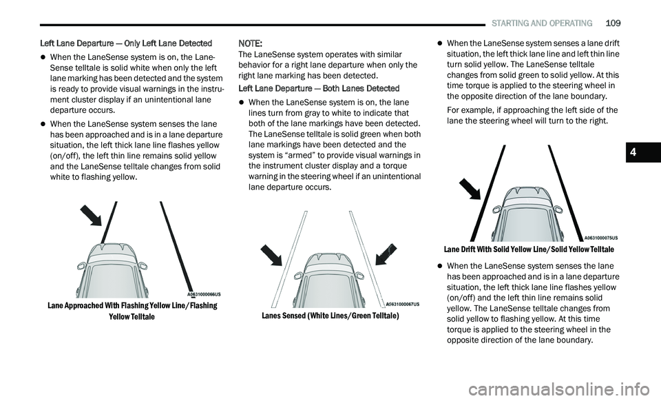
Left Lane Departure — Only Left Lane Detected
When the LaneSense system is on, the Lane-
Sense telltale is solid white when only the left
l a
ne marking has been detected and the system
is ready to provide visual warnings in the instru -
ment cluster display if an unintentional lane
d e
parture occurs.
When the LaneSense system senses the lane
has been approached and is in a lane departure
situation, the left thick lane line flashes yellow
(on/off), the left thin line remains solid yellow
and the LaneSense telltale changes from solid
white to flashing yellow.
Lane Approached With Flashing Yellow Line/Flashing Ye
llow Telltale
NOTE:
The LaneSense system operates with similar
b e
havior for a right lane departure when only the
right lane marking has been detected.
Left Lane Departure — Both Lanes Detected
When the LaneSense system is on, the lane
lines turn from gray to white to indicate that
both of the lane markings have been detected.
The LaneSense telltale is solid green when both
lane markings have been detected and the
system is “armed” to provide visual warnings in
the instrument cluster display and a torque
warning in the steering wheel if an unintentional
lane departure occurs.
Lanes Sensed (White Lines/Green Telltale)
When the LaneSense system senses a lane drift
situation, the left thick lane line and left thin line
turn solid yellow. The LaneSense telltale
changes from solid green to solid yellow. At this
time torque is applied to the steering wheel in
the opposite direction of the lane boundary.
For example, if approaching the left side of the
la
ne the steering wheel will turn to the right.
Lane Drift With Solid Yellow Line/Solid Yellow Telltale
When the LaneSense system senses the lane
has been approached and is in a lane departure
situation, the left thick lane line flashes yellow
(on/off) and the left thin line remains solid
yellow. The LaneSense telltale changes from
solid yellow to flashing yellow. At this time
torque is applied to the steering wheel in the
opposite direction of the lane boundary.
4
Page 112 of 268
110 STARTING AND OPERATING
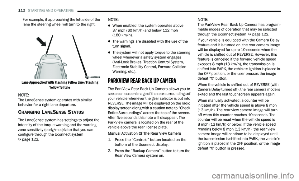
For example, if approaching the left side of the
lane the steering wheel will turn to the right.
Lane Approached With Flashing Yellow Line/Flashing Ye
llow Telltale
NOTE:
The LaneSense system operates with similar
b e
havior for a right lane departure.
CHANGING LANESENSE STATUS
The LaneSense system has settings to adjust the
intensity of the torque warning and the warning
zone sensitivity (early/med/late) that you can
configure through the Uconnect system
Ú page 122.
NOTE:
When enabled, the system operates above
37
mph (60 km/h) and below 112 mph
( 1
80 km/h).
The warnings are disabled with the use of the
turn signal.
The system will not apply torque to the steering
wheel whenever a safety system engages
(Anti-Lock Brakes, Traction Control System,
Electronic Stability Control, Forward Collision
Warning, etc.).
PARKVIEW REAR BACK UP CAMERA
The ParkView Rear Back Up Camera allows you to
see an on-screen image of the rear surroundings of
your vehicle whenever the gear selector is put into
REVERSE. The image will be displayed on the radio
display screen along with a caution note to “Check
Entire Surroundings” across the top of the screen.
After five seconds this note will disappear. The
ParkView camera is located on the rear of the
vehicle above the rear license plate.
Manual Activation Of The Rear View Camera
1. P
ress the “Controls” button located on the
b
ottom of the Uconnect display.
2. Press the “Backup Camera” button to turn the R
ear View Camera system on.
NOTE:
The ParkView Rear Back Up Camera has program -
mable modes of operation that may be selected
t h
rough the Uconnect system Ú page 122.
If your vehicle is equipped with the Camera Delay
f e
ature and it is turned on, the rear camera image
will be displayed for up to 10 seconds when the
vehicle is shifted out of REVERSE. However, this
feature is canceled if the forward vehicle speed
exceeds 8 mph (13 km/h), the transmission is
s h
ifted into PARK, the vehicle's ignition is placed in
the OFF position, or the user presses the image
defeat “X” button.
When the vehicle is shifted out of REVERSE (with
Ca
mera Delay turned off), the rear camera mode is
exited and the last touchscreen appears again.
When manually activated, a counter will be
i n
itiated after the vehicle speed is above 8 mph
( 1
3 km/h). The rear view camera image will turn
of f
when this counter reaches 10 seconds. The
counter will be reset when the vehicle speed is
8 mph (13 km/h) or below. If the vehicle speed
r e
mains below 8 mph (13 km/h), the rear view
c a
mera image will continue to be displayed until
the transmission is shifted into PARK, the vehicle’s
ignition is placed in the OFF position, or the image
defeat “X” button is pressed.
Page 113 of 268

STARTING AND OPERATING 111
When enabled, active guidelines are overlaid on
the image to illustrate the width of the vehicle and
its projected backup path based on the steering
wheel position. Different colored zones indicate
the distance to the rear of the vehicle. The
following table shows the approximate distances
for each zone:
NOTE:
If snow, ice, mud, or any foreign substance builds
u p
on the camera lens, clean the lens, rinse with
water, and dry with a soft cloth. Do not cover the
lens.
REFUELING THE VEHICLE
1. Push the fuel filler door release switch (located in the driver's door map pocket).
Fuel Filler Door Release Switch
2. O pen the fuel filler door.
F
uel Filler Location
Zone
Distance To The Rear Of
Th
e Vehicle
Red 0 - 1
ft
( 0
- 30 cm)
Yellow 1
ft - 6.5 ft
( 3
0 cm - 2 m)
Green 6.5
ft or greater
( 2
m or greater)
WARNING!
Drivers must be careful when backing up even
when using the ParkView Rear Back Up Camera.
Always check carefully behind your vehicle, and
be sure to check for pedestrians, animals, other
vehicles, obstructions, or blind spots before
backing up. You are responsible for the safety of
your surroundings and must continue to pay
attention while backing up. Failure to do so can
result in serious injury or death.
CAUTION!
To avoid vehicle damage, ParkView should
only be used as a parking aid. The ParkView
camera is unable to view every obstacle or
object in your drive path.
To avoid vehicle damage, the vehicle must be
driven slowly when using ParkView to be able
to stop in time when an obstacle is seen. It is
recommended that the driver look frequently
over his/her shoulder when using ParkView.
It is recommended that the driver look
frequently over his/her shoulder when
backing up, especially in sunny weather condi -
tions, since there may be a glare from the sun
a t
certain angles that can make the image on
the touchscreen difficult to see.
4
Page 133 of 268
MULTIMEDIA 131
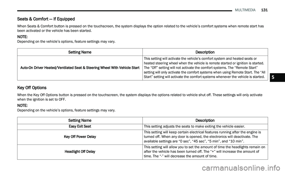
Seats & Comfort — If Equipped
Key Off Options
When Seats & Comfort button is pressed on the touchscreen, the system displays the option related to the vehicle’s comfort systems when remote start has
been activated or the vehicle has been started.
NOTE:
Depending on the vehicle’s options, feature settings may vary.
Setting Name Description
Auto-On Driver Heated/Ventilated Seat & Steering Wheel With Vehicle Start
This setting will activate the vehicle’s comfort system and heated seats or
he
ated steering wheel when the vehicle is remote started or ignition is started.
The “Off” setting will not activate the comfort systems. The “Remote Start”
setting will only activate the comfort systems when using Remote Start. The “All
Start” setting will activate the comfort systems whenever the vehicle is started.
When the Key Off Options button is pressed on the touchscreen, the system displays the options related to vehicle shut off. These settings will only activate
when the ignition is set to OFF.
NOTE:
Depending on the vehicle’s options, feature settings may vary.
Setting Name Description
Easy Exit SeatThis setting adjusts the seats to make exiting the vehicle easier.
Key Off Power Delay This setting will keep certain electrical features running after the engine is
tu
rned off. When any door is opened, the electronics will deactivate. The
available settings are “0 sec”, “45 sec”, “5 min”, and “10 min”.
Headlight Off Delay This setting will allow you to set the amount of time the headlights remain on
af
ter the vehicle has been turned off. The “+” will increase the amount of
time. The “-” will decrease the amount of time.
5
Page 139 of 268
137
(Continued)
SAFETY
SAFETY FEATURES
ANTI-LOCK BRAKE SYSTEM (ABS)
The ABS provides increased vehicle stability and
brake performance under most braking conditions.
The system automatically prevents wheel lock and
enhances vehicle control during braking.
The ABS performs a self-check cycle to ensure that
th
e ABS is working properly each time the vehicle
is started and driven. During this self-check, you
may hear a slight clicking sound as well as some
related motor noises.
The ABS is activated during braking when the
s y
stem detects one or more wheels are beginning
to lock. Road conditions such as ice, snow, gravel,
bumps, railroad tracks, loose debris, or panic stops
may increase the likelihood of ABS activation(s).
You also may experience the following normal
c h
aracteristics when the ABS activates:
ABS motor noise or clicking sounds (you may
continue to hear for a short time after the stop).
Brake pedal pulsations.
A slight drop of the brake pedal at the end of the
stop. The ABS is designed to function with the Original
E
q
uipment Manufacturer (OEM) tires. Modification
may result in degraded ABS performance.
Anti-Lock Brake System (ABS) Warning
Light
The yellow ABS Warning Light will turn on when the
ignition is placed in the ON/RUN mode and may
stay on for as long as four seconds.
If the ABS Warning Light remains on or comes on
w h
ile driving, it indicates that the Anti-Lock portion
of the brake system is not functioning and that
service is required. However, the conventional
brake system will continue to operate normally if
the Anti-Lock Brake Warning Light is on.
If the ABS Warning Light is on, the brake system
s h
ould be serviced as soon as possible to restore
the benefits of Anti-Lock Brakes. If the Anti-Lock
WARNING!
The ABS contains sophisticated electronic
equipment that may be susceptible to interfer -
ence caused by improperly installed or high
out
put radio transmitting equipment. This
interference can cause possible loss of
anti-lock braking capability. Installation of
such equipment should be performed by qual -
ified professionals.
Pumping of the Anti-Lock Brakes will diminish
their effectiveness and may lead to a collision.
Pumping makes the stopping distance longer.
Just press firmly on your brake pedal when you
need to slow down or stop.
The ABS cannot prevent the natural laws of
physics from acting on the vehicle, nor can it
increase braking or steering efficiency beyond
that afforded by the condition of the vehicle
brakes and tires or the traction afforded.
The ABS cannot prevent collisions, including
those resulting from excessive speed in turns,
following another vehicle too closely, or hydro -
planing.
The capabilities of an ABS equipped vehicle
must never be exploited in a reckless or
dangerous manner that could jeopardize the
user’s safety or the safety of others.
WARNING!
6
Page 140 of 268
138 SAFETY
Brake Warning Light does not come on when the
ignition is placed in the ON/RUN mode, have the
light repaired as soon as possible.
ELECTRONIC BRAKE CONTROL (EBC)
S
YSTEM
Your vehicle is equipped with an advanced
Electronic Brake Control (EBC) system. This system
includes Anti-Lock Brake System (ABS), Brake
Assist System (BAS), Electronic Brake Force
Distribution (EBD), Electronic Roll Mitigation
(ERM), Electronic Stability Control (ESC), Hill Start
Assist (HSA), and Traction Control System (TCS).
These systems work together to enhance both
vehicle stability and control in various driving
conditions.
Your vehicle may also be equipped with Rain Brake
S u
pport (RBS) and Ready Alert Braking (RAB).
Brake System Warning Light
The red Brake System Warning Light will turn on
when the ignition is placed in the ON/RUN mode
and may stay on for as long as four seconds.
If the Brake System Warning Light remains on or
com
es on while driving, it indicates that the brake
system is not functioning properly and that
immediate service is required. If the Brake System
Warning Light does not come on when the ignition
is placed in the ON/RUN mode, have the light
repaired as soon as possible.
Brake Assist System (BAS)
The BAS is designed to optimize the vehicle’s
braking capability during emergency braking
maneuvers. The system detects an emergency
braking situation by sensing the rate and amount
of brake application and then applies optimum
pressure to the brakes. This can help reduce
braking distances. The BAS complements the
Anti-Lock Brake System (ABS). Applying the brakes
very quickly results in the best BAS assistance. To
receive the benefit of the system, you must apply
continuous braking pressure during the stopping
sequence (do not “pump” the brakes). Do not
reduce brake pedal pressure unless braking is no
longer desired. Once the brake pedal is released,
the BAS is deactivated.
Electronic Brake Force Distribution (EBD)
EBD manages the distribution of the braking
torque between the front and rear axles by limiting
braking pressure to the rear axle. This is done to
prevent overslip of the rear wheels to avoid vehicle
instability, and to prevent the rear axle from
entering the Anti-Lock Brake System (ABS) before
the front axle.
Electronic Roll Mitigation (ERM)
ERM anticipates the potential for wheel lift by
monitoring the driver’s steering wheel input and
the speed of the vehicle. When ERM determines
that the rate of change of the steering wheel angle
and vehicle’s speed are sufficient to potentially
cause wheel lift, it then applies the appropriate
brake and may also reduce engine power to lessen
the chance that wheel lift will occur. ERM can only
reduce the chance of wheel lift occurring during
severe or evasive driving maneuvers; it cannot
prevent wheel lift due to other factors, such as
road conditions, leaving the roadway, striking
objects or other vehicles.
NOTE:
ERM is disabled any time the ESC is in “Full Off”
m od
e (if equipped). See Ú page 139 in this
section for a complete explanation of the available
E S
C modes.
WARNING!
The Brake Assist System (BAS) cannot prevent
the natural laws of physics from acting on the
vehicle, nor can it increase the traction afforded
by prevailing road conditions. BAS cannot
prevent collisions, including those resulting from
excessive speed in turns, driving on very slippery
surfaces, or hydroplaning. The capabilities of a
BAS-equipped vehicle must never be exploited in
a reckless or dangerous manner, which could
jeopardize the user's safety or the safety of
others.
Page 141 of 268

SAFETY 139
(Continued)
Electronic Stability Control (ESC)
ESC enhances directional control and stability of
the vehicle under various driving conditions. ESC
corrects for oversteering or understeering of the
vehicle by applying the brake of the appropriate
wheel(s) to counteract the above conditions.
Engine power may also be reduced to help the
vehicle maintain the desired path.
Oversteer — when the vehicle is turning more
than appropriate for the steering wheel position.
Understeer — when the vehicle is turning less
than appropriate for the steering wheel position.
ESC uses sensors in the vehicle to determine the
ve
hicle path intended by the driver and compares
it to the actual path of the vehicle. When the actual
path does not match the intended path, ESC
applies the brake of the appropriate wheel to assist in counteracting the oversteer or understeer
condition.
The ESC Activation/Malfunction Indicator Light
l
oc
ated in the instrument cluster will start to flash
as soon as the ESC system becomes active. The
ESC Activation/Malfunction Indicator Light also
flashes when the TCS is active. If the ESC
Activation/Malfunction Indicator Light begins to
flash during acceleration, ease up on the
accelerator and apply as little throttle as possible.
Be sure to adapt your speed and driving to the
prevailing road conditions.
ESC Operating Modes
Depending upon model and mode of operation, the
ESC system may have multiple operating modes.
ESC On
This is the normal operating mode for the ESC.
W h
enever the vehicle is started, the ESC system
will be in this mode. This mode should be used for
most driving conditions. Alternate ESC modes
should only be used for specific reasons as noted
in the following paragraphs.
WARNING!
Many factors, such as vehicle loading, road condi -
tions and driving conditions, influence the chance
t h
at wheel lift or rollover may occur. ERM cannot
prevent all wheel lift or rollovers, especially those
that involve leaving the roadway or striking objects
or other vehicles. The capabilities of an ERM-
equipped vehicle must never be exploited in a
reckless or dangerous manner which could jeop -
ardize the user's safety or the safety of others.
WARNING!
Electronic Stability Control (ESC) cannot
prevent the natural laws of physics from acting
on the vehicle, nor can it increase the traction
afforded by prevailing road conditions. ESC
cannot prevent accidents, including those
resulting from excessive speed in turns, driving
on very slippery surfaces, or hydroplaning. ESC
also cannot prevent accidents resulting from
loss of vehicle control due to inappropriate
driver input for the conditions. Only a safe,
attentive, and skillful driver can prevent acci -
dents. The capabilities of an ESC equipped
v e
hicle must never be exploited in a reckless or
dangerous manner which could jeopardize the
user’s safety or the safety of others.
Vehicle modifications, or failure to properly
maintain your vehicle, may change the handling
characteristics of your vehicle, and may nega -
tively affect the performance of the ESC system.
C h
anges to the steering system, suspension,
braking system, tire type and size or wheel size
may adversely affect ESC performance. Improp -
erly inflated and unevenly worn tires may also
d e
grade ESC performance. Any vehicle modifi-
cation or poor vehicle maintenance that
r e
duces the effectiveness of the ESC system
can increase the risk of loss of vehicle control,
vehicle rollover, personal injury and death.
WARNING!
6
Page 160 of 268

158 SAFETY
How To Engage The Automatic Locking Mode
1. B uckle the combination lap and shoulder
b
elt.
2. Grab the shoulder portion and pull downward u
ntil the entire seat belt is extracted.
3. Allow the seat belt to retract. As the seat belt r
etracts, you will hear a clicking sound. This
indicates the seat belt is now in the Automatic
Locking Mode.
How To Disengage The Automatic Locking Mode
Unbuckle the combination lap/shoulder belt and
a l
low it to retract completely to disengage the
Automatic Locking Mode and activate the vehicle
sensitive (emergency) locking mode.
SUPPLEMENTAL RESTRAINT SYSTEMS
(SRS)
Some of the safety features described in this
section may be standard equipment on some
models, or may be optional equipment on others. If
you are not sure, ask an authorized dealer.
The air bag system must be ready to protect you in
a
collision. The Occupant Restraint Controller
(ORC) monitors the internal circuits and
interconnecting wiring associated with the electrical Air Bag System Components. Your
vehicle may be equipped with the following Air Bag
System Components:
Air Bag System Components
Occupant Restraint Controller (ORC)
Air Bag Warning Light
Steering Wheel and Column
Instrument Panel
Knee Impact Bolsters
Driver and Front Passenger Air Bags
Seat Belt Buckle Switch
Supplemental Side Air Bags
Supplemental Knee Air Bags
Front and Side Impact Sensors
Seat Belt Pretensioners
Seat Track Position Sensors
Air Bag Warning Light
The Occupant Restraint Controller (ORC)
monitors the readiness of the electronic
p
a
rts of the air bag system whenever the
ignition switch is in the START or ON/RUN
position. If the ignition switch is in the OFF position
or in the ACC position, the air bag system is not on
and the air bags will not inflate.
WARNING!
Never place a rear-facing child restraint in
front of an air bag. A deploying passenger
front air bag can cause death or serious injury
to a child 12 years or younger, including a
child in a rear-facing child restraint.
Never install a rear-facing child restraint in the
front seat of a vehicle. Only use a rear-facing
child restraint in the rear seat. If the vehicle
does not have a rear seat, do not transport a
rear-facing child restraint in that vehicle.
WARNING!
The seat belt assembly must be replaced if the
switchable Automatic Locking Retractor (ALR)
feature or any other seat belt function is not
working properly when checked according to
the procedures in the Service Manual.
Failure to replace the seat belt assembly
could increase the risk of injury in collisions.
Do not use the Automatic Locking Mode to
restrain occupants who are wearing the seat
belt or children who are using booster seats.
The locked mode is only used to install
rear-facing or forward-facing child restraints
that have a harness for restraining the child.