2021 CHRYSLER 300 lights
[x] Cancel search: lightsPage 68 of 268

66 GETTING TO KNOW YOUR INSTRUMENT PANEL
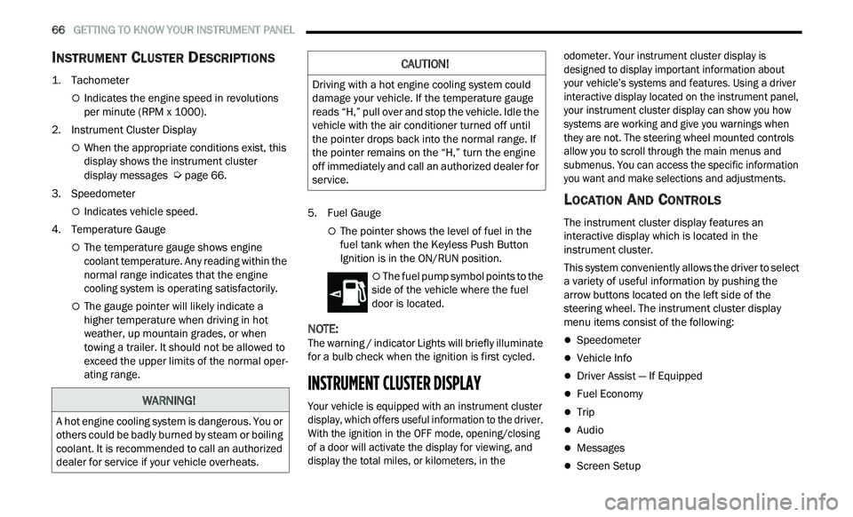
INSTRUMENT CLUSTER DESCRIPTIONS
1. Tachometer
Indicates the engine speed in revolutions
per minute (RPM x 1000).
2. Instrument Cluster Display
When the appropriate conditions exist, this
display shows the instrument cluster
display messages
Ú page 66.
3. S peedometer
Indicates vehicle speed.
4. T emperature Gauge
The temperature gauge shows engine
coolant temperature. Any reading within the
normal range indicates that the engine
cooling system is operating satisfactorily.
The gauge pointer will likely indicate a
higher temperature when driving in hot
weather, up mountain grades, or when
towing a trailer. It should not be allowed to
exceed the upper limits of the normal oper
-
ating range. 5. Fuel Gauge
The pointer shows the level of fuel in the
fuel tank when the Keyless Push Button
Ignition is in the ON/RUN position.
The fuel pump symbol points to the
side of the vehicle where the fuel
d oor
is located.
NOTE:
The warning / indicator Lights will briefly illuminate
f or
a bulb check when the ignition is first cycled.
INSTRUMENT CLUSTER DISPLAY
Your vehicle is equipped with an instrument cluster
display, which offers useful information to the driver.
With the ignition in the OFF mode, opening/closing
of a door will activate the display for viewing, and
display the total miles, or kilometers, in the odometer. Your instrument cluster display is
designed to display important information about
your vehicle’s systems and features. Using a driver
interactive display located on the instrument panel,
your instrument cluster display can show you how
systems are working and give you warnings when
they are not. The steering wheel mounted controls
allow you to scroll through the main menus and
submenus. You can access the specific information
you want and make selections and adjustments.
LOCATION AND CONTROLS
The instrument cluster display features an
interactive display which is located in the
instrument cluster.
This system conveniently allows the driver to select
a
variety of useful information by pushing the
arrow buttons located on the left side of the
steering wheel. The instrument cluster display
menu items consist of the following:
Speedometer
Vehicle Info
Driver Assist — If Equipped
Fuel Economy
Trip
Audio
Messages
Screen Setup
WARNING!
A hot engine cooling system is dangerous. You or
others could be badly burned by steam or boiling
coolant. It is recommended to call an authorized
dealer for service if your vehicle overheats.
CAUTION!
Driving with a hot engine cooling system could
damage your vehicle. If the temperature gauge
reads “H,” pull over and stop the vehicle. Idle the
vehicle with the air conditioner turned off until
the pointer drops back into the normal range. If
the pointer remains on the “H,” turn the engine
off immediately and call an authorized dealer for
service.
Page 73 of 268

GETTING TO KNOW YOUR INSTRUMENT PANEL 71
NOTE:
The charging system is independent from load
reduction. The charging system performs a diag
-
nostic on the charging system continuously.
If the Battery Charge Warning Light is on it may
indicate a problem with the charging system
Ú page 73.
The electrical loads that may be switched off (if
e q
uipped), and vehicle functions which can be
affected by load reduction:
Heated Seat/Vented Seats/Heated Wheel —
If Equipped
Heated/Cooled Cup Holders — If Equipped
Rear Defroster And Heated Mirrors
HVAC System
115 Volts AC Power Inverter System
Audio and Telematics System
Loss of the battery charge may indicate one or
m or
e of the following conditions:
The charging system cannot deliver enough
electrical power to the vehicle system because
the electrical loads are larger than the capability
of the charging system. The charging system is
still functioning properly.
Turning on all possible vehicle electrical loads
(e.g. HVAC to max settings, exterior and interior
lights, overloaded power outlets +12 Volts, 115 Volts AC, USB ports) during certain driving
c
on
ditions (city driving, towing, frequent stop -
ping).
Installing options like additional lights, upfitter
electrical accessories, audio systems, alarms
and similar devices.
Unusual driving cycles (short trips separated by
long parking periods).
The vehicle was parked for an extended period
of time (weeks, months).
The battery was recently replaced and was not
charged completely.
The battery was discharged by an electrical load
left on when the vehicle was parked.
The battery was used for an extended period
with the engine not running to supply radio,
lights, chargers, +12 Volt portable appliances
like vacuum cleaners, game consoles and
similar devices.
What to do when an electrical load reduction
a c
tion message is present (“Battery Saver On” or
“Battery Saver Mode”)
During a trip:
Reduce power to unnecessary loads if possible:
Turn off redundant lights (interior or exte -
rior)
Check what may be plugged in to power
outlets +12 Volts, 115 Volts AC, USB ports
Check HVAC settings (blower, temperature)
Check the audio settings (volume)
After a trip:
Check if any aftermarket equipment was
installed (additional lights, upfitter electrical
accessories, audio systems, alarms) and review
specifications if any (load and Ignition Off Draw
currents).
Evaluate the latest driving cycles (distance,
driving time and parking time).
The vehicle should have service performed if
the message is still present during consecutive
trips and the evaluation of the vehicle and
driving pattern did not help to identify the cause.
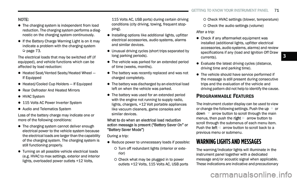
PROGRAMMABLE FEATURES
The instrument cluster display can be used to view
or change the following settings. Push the up
or
down arrow button to scroll through the main
menus, then push the ri
ght arrow button to
scroll through the submenus of each menu item.
P u
sh the left arrow button to scroll back to a
previous menu or submenu.
WARNING LIGHTS AND MESSAGES
The warning/indicator lights will illuminate in the
instrument panel together with a dedicated
message and/or acoustic signal when applicable.
These indications are indicative and precautionary
3
Page 74 of 268

72 GETTING TO KNOW YOUR INSTRUMENT PANEL
and as such must not be considered as exhaustive
and/or alternative to the information contained in
the Owner’s Manual, which you are advised to read
carefully in all cases. Always refer to the
information in this chapter in the event of a failure
indication. All active warning lights will display first
if applicable. The system check menu may appear
different based upon equipment options and
current vehicle status. Some warning lights are
optional and may not appear.
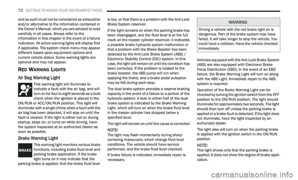
RED WARNING LIGHTS
Air Bag Warning Light
This warning light will illuminate to
indicate a fault with the air bag, and will
t
u
rn on for four to eight seconds as a bulb
check when the ignition is placed in the
ON/RUN or ACC/ON/RUN position. This light will
illuminate with a single chime when a fault with the
air bag has been detected, it will stay on until the
fault is cleared. If the light is either not on during
startup, stays on, or turns on while driving, have
the system inspected at an authorized dealer as
soon as possible.
Brake Warning Light
This warning light monitors various brake
functions, including brake fluid level and
p a
rking brake application. If the brake
light turns on it may indicate that the
parking brake is applied, that the brake fluid level is low, or that there is a problem with the Anti-Lock
Brake System reservoir.
If the light remains on when the parking brake has
b
e
en disengaged, and the fluid level is at the full
mark on the master cylinder reservoir, it indicates
a possible brake hydraulic system malfunction or
that a problem with the Brake Booster has been
detected by the Anti-Lock Brake System (ABS) /
Electronic Stability Control (ESC) system. In this
case, the light will remain on until the condition has
been corrected. If the problem is related to the
brake booster, the ABS pump will run when
applying the brake, and a brake pedal pulsation
may be felt during each stop.
The dual brake system provides a reserve braking
c a
pacity in the event of a failure to a portion of the
hydraulic system. A leak in either half of the dual
brake system is indicated by the Brake Warning
Light, which will turn on when the brake fluid level
in the master cylinder has dropped below a
specified level.
The light will remain on until the cause is corrected.
NOTE:
The light may flash momentarily during sharp
c or
nering maneuvers, which change fluid level
conditions. The vehicle should have service
performed, and the brake fluid level checked.
If brake failure is indicated, immediate repair is
ne
cessary. Vehicles equipped with the Anti-Lock Brake System
(
A
BS) are also equipped with Electronic Brake
Force Distribution (EBD). In the event of an EBD
failure, the Brake Warning Light will turn on along
with the ABS Light. Immediate repair to the ABS
system is required.
Operation of the Brake Warning Light can be
c h
ecked by turning the ignition switch from the OFF
position to the ON/RUN position. The light should
illuminate for approximately two seconds. The light
should then turn off unless the parking brake is
applied or a brake fault is detected. If the light does
not illuminate, have the light inspected by an
authorized dealer.
The light also will turn on when the parking brake
i s
applied with the ignition switch in the ON/RUN
position.
NOTE:
This light shows only that the parking brake is
a p
plied. It does not show the degree of brake appli -
cation.
WARNING!
Driving a vehicle with the red brake light on is
dangerous. Part of the brake system may have
failed. It will take longer to stop the vehicle. You
could have a collision. Have the vehicle checked
immediately.
Page 76 of 268

74 GETTING TO KNOW YOUR INSTRUMENT PANEL
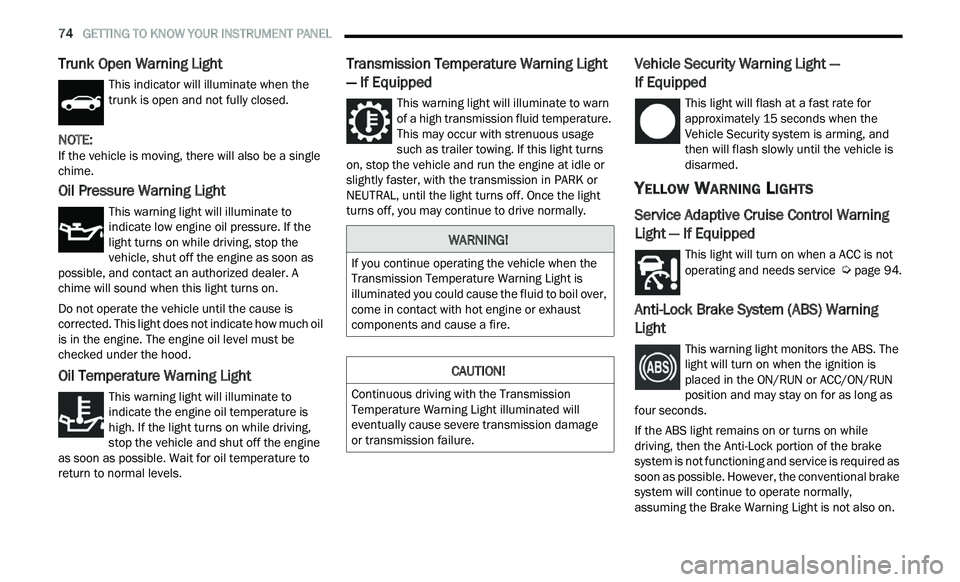
Trunk Open Warning Light
This indicator will illuminate when the
trunk is open and not fully closed.
NOTE:
If the vehicle is moving, there will also be a single
c h
ime.
Oil Pressure Warning Light
This warning light will illuminate to
indicate low engine oil pressure. If the
li
ght turns on while driving, stop the
vehicle, shut off the engine as soon as
possible, and contact an authorized dealer. A
chime will sound when this light turns on.
Do not operate the vehicle until the cause is
c or
rected. This light does not indicate how much oil
is in the engine. The engine oil level must be
checked under the hood.
Oil Temperature Warning Light
This warning light will illuminate to
indicate the engine oil temperature is
h i
gh. If the light turns on while driving,
stop the vehicle and shut off the engine
as soon as possible. Wait for oil temperature to
return to normal levels.
Transmission Temperature Warning Light
— If Equipped
This warning light will illuminate to warn
of a high transmission fluid temperature.
T h
is may occur with strenuous usage
such as trailer towing. If this light turns
on, stop the vehicle and run the engine at idle or
slightly faster, with the transmission in PARK or
NEUTRAL, until the light turns off. Once the light
turns off, you may continue to drive normally.
Vehicle Security Warning Light —
If Equipped
This light will flash at a fast rate for
approximately 15 seconds when the
V e
hicle Security system is arming, and
then will flash slowly until the vehicle is
disarmed.
YELLOW WARNING LIGHTS
Service Adaptive Cruise Control Warning
Light — If Equipped
This light will turn on when a ACC is not
operating and needs service Ú page 94.
Anti-Lock Brake System (ABS) Warning
Light
This warning light monitors the ABS. The
light will turn on when the ignition is
p
l
aced in the ON/RUN or ACC/ON/RUN
position and may stay on for as long as
four seconds.
If the ABS light remains on or turns on while
dr
iving, then the Anti-Lock portion of the brake
system is not functioning and service is required as
soon as possible. However, the conventional brake
system will continue to operate normally,
assuming the Brake Warning Light is not also on.
WARNING!
If you continue operating the vehicle when the
Transmission Temperature Warning Light is
illuminated you could cause the fluid to boil over,
come in contact with hot engine or exhaust
components and cause a fire.
CAUTION!
Continuous driving with the Transmission
Temperature Warning Light illuminated will
eventually cause severe transmission damage
or transmission failure.
Page 79 of 268

GETTING TO KNOW YOUR INSTRUMENT PANEL 77
Please note that the TPMS is not a substitute for
proper tire maintenance, and it is the driver’s
responsibility to maintain correct tire pressure,
even if underinflation has not reached the level to
trigger illumination of the TPMS low tire pressure
warning light.
Your vehicle has also been equipped with a TPMS
ma
lfunction indicator to indicate when the system
is not operating properly. The TPMS malfunction
indicator is combined with the low tire pressure
warning light. When the system detects a
malfunction, the warning light will flash for
approximately one minute and then remain
continuously illuminated. This sequence will
continue upon subsequent vehicle start-ups as
long as the malfunction exists. When the
malfunction indicator is illuminated, the system
may not be able to detect or signal low tire
pressure as intended. TPMS malfunctions may
occur for a variety of reasons, including the
installation of replacement or alternate tires or
wheels on the vehicle that prevent the TPMS from
functioning properly. Always check the TPMS
malfunction warning light after replacing one or
more tires or wheels on your vehicle to ensure that
the replacement or alternate tires and wheels
allow the TPMS to continue to function properly.
YELLOW INDICATOR LIGHTS
Forward Collision Warning Off Indicator
Light — If Equipped
This indicator light illuminates to indicate
that Forward Collision Warning is off
Ú page 146.
GREEN INDICATOR LIGHTS
Adaptive Cruise Control (ACC) Set Without
Target Vehicle Light — If Equipped
This will display the distance setting for
the ACC system when the system is
en
gaged Ú page 94.
Adaptive Cruise Control (ACC) Set With
Target Vehicle Light — If Equipped
This will display when the ACC is set and
a vehicle in front is detected Ú page 94.
Cruise Control Set Indicator Light —
If Equipped
This indicator light will illuminate when
the cruise control is set to the desired
s p
eed Ú page 92.
Front Fog Indicator Light — If Equipped
This indicator light will illuminate when
the front fog lights are on Ú page 40.
CAUTION!
The TPMS has been optimized for the original
equipment tires and wheels. TPMS pressures
and warning have been established for the tire
size equipped on your vehicle. Undesirable
system operation or sensor damage may result
when using replacement equipment that is not
of the same size, type, and/or style. Aftermarket
wheels can cause sensor damage. Using
aftermarket tire sealants may cause the Tire
Pressure Monitoring System (TPMS) sensor to
become inoperable. After using an aftermarket
tire sealant it is recommended that you take
your vehicle to an authorized dealer to have your
sensor function checked.
3
Page 80 of 268

78 GETTING TO KNOW YOUR INSTRUMENT PANEL
LaneSense Indicator Light — If Equipped
The LaneSense indicator light illuminates
solid green when both lane markings
ha
ve been detected and the system is
“armed” and ready to provide visual and
torque warnings if an unintentional lane departure
occurs
Ú page 108.
Parking/Headlights On Indicator Light
This indicator light will illuminate when
the parking lights or headlights are
tu
rned on Ú page 40.
Sport Mode Indicator Light
This light will turn on when Sport Mode is
active.
Turn Signal Indicator Lights
When the left or right turn signal is
activated, the turn signal indicator will
f
l
ash independently and the
corresponding exterior turn signal lamps
will flash. Turn signals can be activated when the
multifunction lever is moved down (left) or up
(right).
NOTE:
A continuous chime will sound if the vehicle is
driven more than 1 mile (1.6 km) with either
t u
rn signal on.
Check for an inoperative outside light bulb if
either indicator flashes at a rapid rate.
ECO Mode Indicator Light — If Equipped
This light will turn on when ECO mode is
active.
WHITE INDICATOR LIGHTS
Adaptive Cruise Control (ACC) Ready Light
— If Equipped
This light will turn on when ACC has been
turned on, but is not set Ú page 94.
Cruise Control Ready Indicator Light
This indicator light will illuminate when
the cruise control is ready, but not set
Ú page 92.
LaneSense Indicator Light — If Equipped
When the LaneSense system is ON, but
not armed, the LaneSense indicator light
il
luminates solid white. This occurs when
only left, right, or neither lane line has
been detected. If a single lane line is detected, the
system is ready to provide only visual warnings if
an unintentional lane departure occurs on the
detected lane line
Ú page 108.
BLUE INDICATOR LIGHTS
High Beam Indicator Light
This indicator light will illuminate to
indicate that the high beam headlights are
on
. With the low beams activated, push
the multifunction lever forward (toward the
front of the vehicle) to turn on the high beams. Pull
the multifunction lever rearward (toward the rear of
the vehicle) to turn off the high beams. If the high
beams are off, pull the lever toward you for a
temporary high beam on, "flash to pass" scenario.
Page 100 of 268

98 STARTING AND OPERATING
When ACC Is Active:
NOTE:
When you use the SET (-) button to decelerate, if
the engine’s braking power does not slow the
vehicle sufficiently to reach the set speed, the
brake system will automatically slow the
vehicle.
The ACC system applies the brake down to a full
stop when following the vehicle in front. If your
vehicle follows the vehicle in front to a standstill,
your vehicle will release the brakes two seconds
after coming to a full stop.
The ACC will bring the vehicle to a complete stop
while following a vehicle in front and hold the
vehicle for two seconds in the stop position. If
the vehicle in front does not start moving within
two seconds, the ACC system will display a
message that the system will release the brakes
and that the brakes must be applied manually.
An audible chime will sound when the brakes
are released.
The ACC system maintains set speed when
driving uphill and downhill. However, a slight
speed change on moderate hills is normal. In
addition, downshifting may occur while climbing
uphill or descending downhill. This is normal
operation and necessary to maintain set speed.
When driving uphill and downhill, the ACC
system will cancel if the braking temperature
exceeds normal range (overheated).
Setting The Following Distance In ACC
The specified following distance for ACC can be set
by varying the distance setting between four bars
(longest), three bars (long), two bars (medium) and
one bar (short). Using this distance setting and the
vehicle speed, ACC calculates and sets the
distance to the vehicle ahead. This distance
setting displays in the instrument cluster display.
Distance Settings
To increase the distance setting, push the
D i
stance Setting Increase button and release.
Each time the button is pushed, the distance
setting increases by one bar (longer). To decrease the distance setting, push the
D
i
stance Setting Decrease button and release.
Each time the button is pushed, the distance
setting decreases by one bar (shorter).
If there is no vehicle ahead, the vehicle will
ma
intain the set speed. If a slower moving vehicle
is detected in the same lane, the instrument
cluster display will show the ACC Set With Target
Detected Indicator Light, and the system will adjust
the vehicle speed automatically to maintain the
distance setting, regardless of the set speed.
The vehicle will then maintain the set distance
u n
til:
The vehicle ahead accelerates to a speed above
the set speed.
The vehicle ahead moves out of your lane or
view of the sensor.
The distance setting is changed.
The system disengages Ú page 96.
The maximum braking applied by ACC is limited;
h ow
ever, the driver can always apply the brakes
manually, if necessary.
NOTE:
The brake lights will illuminate whenever the ACC
s y
stem applies the brakes.
A Proximity Warning will alert the driver if ACC
pr
edicts that its maximum braking level is not
sufficient to maintain the set distance. If this
1 — Longest Distance Setting (Four Bars)
2 — Medium Distance Setting (Two Bars)
3 — Long Distance Setting (Three Bars)
4 — Short Distance Setting (One Bar)
Page 120 of 268

118 STARTING AND OPERATING
Towing Requirements — Trailer Lights And
Wiring
Whenever you pull a trailer, regardless of the trailer
size, stop lights and turn signals on the trailer are
required for motoring safety.
The Trailer Tow Package may include a four- and
se
ven-pin wiring harness. Use a factory approved
trailer harness and connector.
NOTE:
Do not cut or splice wiring into the vehicle’s wiring
h a
rness. The electrical connections are all complete to the
v
e
hicle but you must mate the harness to a trailer
connector. Refer to the following illustrations.
NOTE:
Disconnect trailer wiring connector from the
vehicle before launching a boat (or any other
device plugged into vehicle’s electrical connect)
into water.
Be sure to reconnect after clear from water
area.
Four-Pin Connector Seven-Pin Connector
TOWING TIPS
Before setting out on a trip, practice turning,
stopping, and backing up the trailer in an area
located away from heavy traffic.
Towing any trailer will increase your stopping
distance. When towing, you should allow for
additional space between your vehicle and the
vehicle in front of you. Failure to do so could
result in an accident.
CAUTION!
If the trailer weighs more than 1,000 lb (453 kg)
loaded, it should have its own brakes and they
should be of adequate capacity. Failure to do
this could lead to accelerated brake lining wear,
higher brake pedal effort, and longer stopping
distances.
WARNING!
1 — Ground
2 — Park
3 — Left Stop/Turn
4 — Right Stop/Turn
1 — Backup Lamps
2 — Running Lamps
3 — Left Stop/Turn
4 — Ground
5 — Battery
6 — Right Stop/Turn
7 — Electric Brakes