2021 CHRYSLER 300 flat tire
[x] Cancel search: flat tirePage 152 of 268

150 SAFETY
Tire Pressure Monitoring System Display
Low Tire Pressure Monitoring System Display
Should this occur, you should stop as soon as
p os
sible and inflate the tires with a low pressure
condition (those shown in a different color in the
instrument cluster graphic) to the vehicle’s
recommended cold placard pressure inflation
value as shown in the “Inflate to XX” message.
Once the system receives the updated tire pressures, the system will automatically update,
the graphic display in the instrument cluster will
change color back to the original color, and the
TPMS Warning Light will turn off. The vehicle may
need to be driven for up to 20
minutes above
1 5
mph (24 km/h) in order for the TPMS to receive
t h
is information.
NOTE:
When filling warm tires, the tire pressure may need
t o
be increased up to an additional 4 psi (28 kPa)
above the recommended cold placard pressure in
order to turn the TPMS Warning Light off.
Service Tire Pressure System Warning
If a system fault is detected, the Tire Pressure
Monitoring System (TPMS) Warning Light will flash
on and off for 75 seconds and then remain on
solid. The system fault will also sound a chime. In
addition, the instrument cluster will display a
"Service Tire Pressure System" message for a
minimum of five seconds and then display dashes
(- -) in place of the pressure value to indicate which
sensor is not being received.
If the ignition switch is cycled, this sequence will
r e
peat, providing the system fault still exists. If the
system fault no longer exists, the TPMS Warning
Light will no longer flash, and the "Service Tire
Pressure System" message will no longer display,
and a pressure value will display in place of the
dashes. A system fault can occur due to any of the
following:
Signal interference due to electronic devices or
driving next to facilities emitting the same radio
frequencies as the TPMS sensors.
Accumulation of snow or ice around the wheels
or wheel housings.
Using tire chains on the vehicle.
Using wheels/tires not equipped with TPMS
sensors.
Vehicles With Compact Spare
1. T he compact spare tire or non-matching full
s
ize does not have a Tire Pressure Monitoring
System sensor. Therefore, the TPMS will not
monitor the pressure in the compact spare
tire.
2. I f you install the compact or non-matching full
s
ize spare tire in place of a road tire that has a
pressure below the low-pressure warning limit,
upon the next ignition key cycle, the TPMS
Warning Light will remain on and a chime will
sound. In addition, the graphic in the
instrument cluster will still display a different
color pressure value and an "Inflate to XX"
message.
Page 160 of 268

158 SAFETY
How To Engage The Automatic Locking Mode
1. B uckle the combination lap and shoulder
b
elt.
2. Grab the shoulder portion and pull downward u
ntil the entire seat belt is extracted.
3. Allow the seat belt to retract. As the seat belt r
etracts, you will hear a clicking sound. This
indicates the seat belt is now in the Automatic
Locking Mode.
How To Disengage The Automatic Locking Mode
Unbuckle the combination lap/shoulder belt and
a l
low it to retract completely to disengage the
Automatic Locking Mode and activate the vehicle
sensitive (emergency) locking mode.
SUPPLEMENTAL RESTRAINT SYSTEMS
(SRS)
Some of the safety features described in this
section may be standard equipment on some
models, or may be optional equipment on others. If
you are not sure, ask an authorized dealer.
The air bag system must be ready to protect you in
a
collision. The Occupant Restraint Controller
(ORC) monitors the internal circuits and
interconnecting wiring associated with the electrical Air Bag System Components. Your
vehicle may be equipped with the following Air Bag
System Components:
Air Bag System Components
Occupant Restraint Controller (ORC)
Air Bag Warning Light
Steering Wheel and Column
Instrument Panel
Knee Impact Bolsters
Driver and Front Passenger Air Bags
Seat Belt Buckle Switch
Supplemental Side Air Bags
Supplemental Knee Air Bags
Front and Side Impact Sensors
Seat Belt Pretensioners
Seat Track Position Sensors
Air Bag Warning Light
The Occupant Restraint Controller (ORC)
monitors the readiness of the electronic
p
a
rts of the air bag system whenever the
ignition switch is in the START or ON/RUN
position. If the ignition switch is in the OFF position
or in the ACC position, the air bag system is not on
and the air bags will not inflate.
WARNING!
Never place a rear-facing child restraint in
front of an air bag. A deploying passenger
front air bag can cause death or serious injury
to a child 12 years or younger, including a
child in a rear-facing child restraint.
Never install a rear-facing child restraint in the
front seat of a vehicle. Only use a rear-facing
child restraint in the rear seat. If the vehicle
does not have a rear seat, do not transport a
rear-facing child restraint in that vehicle.
WARNING!
The seat belt assembly must be replaced if the
switchable Automatic Locking Retractor (ALR)
feature or any other seat belt function is not
working properly when checked according to
the procedures in the Service Manual.
Failure to replace the seat belt assembly
could increase the risk of injury in collisions.
Do not use the Automatic Locking Mode to
restrain occupants who are wearing the seat
belt or children who are using booster seats.
The locked mode is only used to install
rear-facing or forward-facing child restraints
that have a harness for restraining the child.
Page 180 of 268
178 SAFETY
(Continued)
lug nuts/bolt torque for tightness. Check the tires
(including spare) for proper cold inflation pressure.
Lights
Have someone observe the operation of brake
lights and exterior lights while you work the
controls. Check turn signal and high beam
indicator lights on the instrument panel.
Door Latches
Check for proper closing, latching, and locking.
Fluid Leaks
Check area under the vehicle after overnight
parking for fuel, coolant, oil, or other fluid leaks.
Also, if gasoline fumes are detected or if fuel or
brake fluid leaks are suspected, the cause should
be located and corrected immediately.
EXHAUST GAS
The best protection against carbon monoxide entry
into the vehicle body is a properly maintained
engine exhaust system.
Whenever a change is noticed in the sound of the
ex
haust system, when exhaust fumes can be
detected inside the vehicle, or when the underside
or rear of the vehicle is damaged, have an
authorized dealer inspect the complete exhaust
system and adjacent body areas for broken,
damaged, deteriorated, or mispositioned parts.
Open seams or loose connections could permit
exhaust fumes to seep into the passenger
compartment. In addition, inspect the exhaust
system each time the vehicle is raised for
lubrication or oil change. Replace as required.
CARBON MONOXIDE WARNINGS
WARNING!
Exhaust gases can injure or kill. They contain
carbon monoxide (CO), which is colorless and
odorless. Breathing it can make you
unconscious and can eventually poison you. To
avoid breathing (CO), follow these safety tips:
Do not run the engine in a closed garage or in
confined areas any longer than needed to
move your vehicle in or out of the area.
If you are required to drive with the trunk/lift -
gate/rear doors open, make sure that all
w i
ndows are closed and the climate control
BLOWER switch is set at high speed. DO NOT
use the recirculation mode.
If it is necessary to sit in a parked vehicle with
the engine running, adjust your heating or
cooling controls to force outside air into the
vehicle. Set the blower at high speed.
WARNING!
WARNING!
Carbon monoxide (CO) in exhaust gases is
deadly. Follow the precautions below to prevent
carbon monoxide poisoning:
Do not inhale exhaust gases. They contain
carbon monoxide, a colorless and odorless
gas, which can kill. Never run the engine in a
closed area, such as a garage, and never sit in
a parked vehicle with the engine running for
an extended period. If the vehicle is stopped in
an open area with the engine running for more
than a short period, adjust the ventilation
system to force fresh, outside air into the
vehicle.
Guard against carbon monoxide with proper
maintenance. Have the exhaust system
inspected every time the vehicle is raised.
Have any abnormal conditions repaired
promptly. Until repaired, drive with all side
windows fully open.
Page 182 of 268
180 IN CASE OF EMERGENCY
(Continued)
ASSIST Call
The ASSIST Button is used to automatically
con
nect you to any one of the following support
centers:
Roadside Assistance – If you get a flat tire, or
need a tow, just push the ASSIST button and you
will be connected to a representative for assis -
tance. Roadside Assistance will know what
v e
hicle you’re driving and its location. Additional
fees may apply for roadside Assistance.
SiriusXM Guardian™ Customer Care – In-vehicle
support for SiriusXM Guardian™.
Vehicle Customer Care – Total support for all
other vehicle issues.
Uconnect Customer Care - Total support for
Radio, Phone and NAV issues.
SOS Call
1. P ush the SOS Call button on the Rearview
Mi
rror.
NOTE:
In case the SOS Call button is pushed in error,
t h
ere will be a 10 second delay before the SOS Call
system initiates a call to a SOS operator. To cancel
the SOS Call connection, push the SOS call button
on the Rearview Mirror or press the cancellation
button on the Device Screen. Termination of the
SOS Call will turn off the green LED light on the
Rearview Mirror. 2. T
he LED light located between the ASSIST and
S
OS buttons on the Rearview Mirror will turn
green once a connection to a SOS operator has
been made.
3. Once a connection between the vehicle and a S
OS operator is made, the SOS Call system
may transmit the following important vehicle
information to a SOS operator:
Indication that the occupant placed a SOS
Call.
The vehicle brand.
The last known GPS coordinates of the
vehicle.
4. You should be able to speak with the SOS op
erator through the vehicle audio system to
determine if additional help is needed.
NOTE:
Your vehicle may be transmitting data as
authorized by the subscriber.
Once a connection is made between the
vehicle’s SOS Call system and the SOS oper -
ator, the SOS operator may be able to open
a
voice connection with the vehicle to deter -
mine if additional help is needed. Once the
S O
S operator opens a voice connection with
the vehicle’s SOS Call system, the operator
should be able to speak with you or other
vehicle occupants and hear sounds occur -
ring in the vehicle. The vehicle’s SOS Call
s y
stem will attempt to remain connected
with the SOS operator until the SOS oper -
ator terminates the connection.
5. T he SOS operator may attempt to contact
a
ppropriate emergency responders and
provide them with important vehicle
information and GPS coordinates.
WARNING!
ALWAYS obey traffic laws and pay attention to
the road. ALWAYS drive safely with your hands on
the steering wheel. You have full responsibility
and assume all risks related to the use of the
Uconnect and SiriusXM Guardian™ features and
applications in this vehicle. Only use Uconnect
features and SiriusXM Guardian™ services when
it is safe to do so. Failure to do so may result in
an accident involving serious injury or death.
WARNING!
If anyone in the vehicle could be in danger
(e.g., fire or smoke is visible, dangerous road
conditions or location), do not wait for voice
contact from an Emergency Services Agent. All
occupants should exit the vehicle immediately
and move to a safe location.
Page 185 of 268
IN CASE OF EMERGENCY 183
3. Apply the parking brake.
4. P lace the gear selector into PARK (P).
5
. T urn the ignition to the OFF position.
6
. B lock both the front and rear of the wheel
d
iagonally opposite the jacking position. For
example, if the driver’s front wheel is being
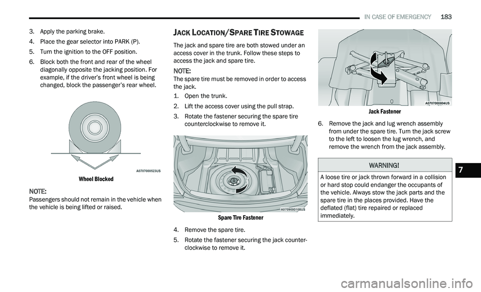
changed, block the passenger’s rear wheel.
Wheel Blocked
NOTE:
Passengers should not remain in the vehicle when
t h
e vehicle is being lifted or raised.
JACK LOCATION/SPARE TIRE STOWAGE
The jack and spare tire are both stowed under an
access cover in the trunk. Follow these steps to
access the jack and spare tire.
NOTE:
The spare tire must be removed in order to access
t h
e jack.
1. Open the trunk.
2
. Li ft the access cover using the pull strap.
3
. R otate the fastener securing the spare tire
c
ounterclockwise to remove it.
Spare Tire Fastener
4. R emove the spare tire.
5
. R otate the fastener securing the jack counter -
c
lockwise to remove it.
Jack Fastener
6. R emove the jack and lug wrench assembly
f
rom under the spare tire. Turn the jack screw
to the left to loosen the lug wrench, and
remove the wrench from the jack assembly.
WARNING!
A loose tire or jack thrown forward in a collision
or hard stop could endanger the occupants of
the vehicle. Always stow the jack parts and the
spare tire in the places provided. Have the
deflated (flat) tire repaired or replaced
immediately.7
Page 186 of 268
184 IN CASE OF EMERGENCY
(Continued)
JACKING AND CHANGING A TIRE
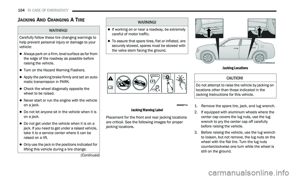
Jacking Warning Label
Placement for the front and rear jacking locations
ar
e critical. See the following images for proper
jacking locations.
Jacking Locations
1. R emove the spare tire, jack, and lug wrench.
2
. I f equipped with aluminum wheels where the
c
enter cap covers the lug nuts, use the lug
wrench to pry the center cap off carefully
before raising the vehicle.
3. Before raising the vehicle, use the lug wrench t
o loosen, but not remove, the lug nuts on the
wheel with the flat tire. Turn the lug nuts
counterclockwise one turn while the wheel is
still on the ground.
WARNING!
Carefully follow these tire changing warnings to
help prevent personal injury or damage to your
vehicle:
Always park on a firm, level surface as far from
the edge of the roadway as possible before
raising the vehicle.
Turn on the Hazard Warning Flashers.
Apply the parking brake firmly and set an auto -
matic transmission in PARK.
Chock the wheel diagonally opposite the
wheel to be raised.
Never start or run the engine with the vehicle
on a jack.
Do not let anyone sit in the vehicle when it is
on a jack.
Do not get under the vehicle when it is on a
jack. If you need to get under a raised vehicle,
take it to a service center where it can be
raised on a lift.
Only use the jack in the positions indicated for
lifting this vehicle during a tire change.
If working on or near a roadway, be extremely
careful of motor traffic.
To assure that spare tires, flat or inflated, are
securely stowed, spares must be stowed with
the valve stem facing the ground.
WARNING!
CAUTION!
Do not attempt to raise the vehicle by jacking on
locations other than those indicated in the
Jacking Instructions for this vehicle.
Page 187 of 268
IN CASE OF EMERGENCY 185
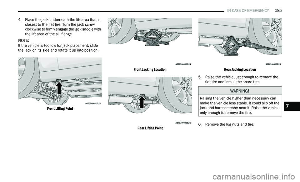
4. Place the jack underneath the lift area that is
closest to the flat tire. Turn the jack screw
clockwise to firmly engage the jack saddle with
the lift area of the sill flange.
NOTE:
If the vehicle is too low for jack placement, slide
t h
e jack on its side and rotate it up into position.
Front Lifting Point Front Jacking Location
Rear Lifting Point Rear Jacking Location
5. R aise the vehicle just enough to remove the
f
lat tire and install the spare tire.
6. R emove the lug nuts and tire.
WARNING!
Raising the vehicle higher than necessary can
make the vehicle less stable. It could slip off the
jack and hurt someone near it. Raise the vehicle
only enough to remove the tire.
7
Page 188 of 268
186 IN CASE OF EMERGENCY
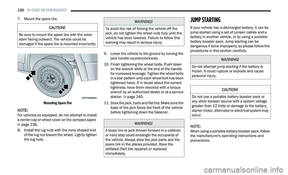
7. Mount the spare tire.
Mounting Spare Tire
NOTE:
For vehicles so equipped, do not attempt to install
a
center cap or wheel cover on the compact spare
Ú page 236.
8. I nstall the lug nuts with the cone shaped end
of
the lug nut toward the wheel. Lightly tighten
the lug nuts. 9. Low
er the vehicle to the ground by turning the
j
ack handle counterclockwise.
10. Finish tightening the wheel bolts. Push down on
the wrench while at the end of the handle
for increased leverage. Tighten the wheel bolts
in a star pattern until each wheel bolt has been
tightened twice. If in doubt about the correct
tightness, have them checked with a torque
wrench by an authorized dealer or at a service
station
Ú page 245.
11. S tow the jack, tools and flat tire. Make sure the
b
ase of the jack faces the front of the vehicle
before tightening down the fastener.
JUMP STARTING
If your vehicle has a discharged battery, it can be
jump started using a set of jumper cables and a
battery in another vehicle, or by using a portable
battery booster pack. Jump starting can be
dangerous if done improperly, so please follow the
procedures in this section carefully.
NOTE:
When using a portable battery booster pack, follow
t h
e manufacturer's operating instructions and
precautions.
CAUTION!
Be sure to mount the spare tire with the valve
stem facing outward. The vehicle could be
damaged if the spare tire is mounted incorrectly.
WARNING!
To avoid the risk of forcing the vehicle off the
jack, do not tighten the wheel nuts fully until the
vehicle has been lowered. Failure to follow this
warning may result in serious injury.
WARNING!
A loose tire or jack thrown forward in a collision
or hard stop could endanger the occupants of
the vehicle. Always stow the jack parts and the
spare tire in the places provided. Have the
deflated (flat) tire repaired or replaced
immediately.
WARNING!
Do not attempt jump starting if the battery is
frozen. It could rupture or explode and cause
personal injury.
CAUTION!
Do not use a portable battery booster pack or
any other booster source with a system voltage
greater than 12 Volts or damage to the battery,
starter motor, alternator or electrical system may
occur.