2021 CHEVROLET SILVERADO 2500HD window
[x] Cancel search: windowPage 272 of 433
Chevrolet Silverado 2500 HD/3500 HD Owner Manual (GMNA-Localizing-U.
S./Canada/Mexico-14632154) - 2021 - CRC - 11/20/20
Driving and Operating 271
When parking your vehicle and your trailer
on a hill:1. Press the brake pedal, but do not shift into P (Park) yet. Turn the wheels into
the curb if facing downhill or into traffic
if facing uphill.
2. Have someone place chocks under the trailer wheels.
3. Gradually release the brake pedal to allow the chocks to absorb the load of
the trailer.
4. Reapply the brake pedal. Then apply the parking brake and shift into P (Park).
5. Release the brake pedal.
Leaving After Parking on a Hill
1. Apply and hold the brake pedal.
.Start the engine.
.Shift into a gear.
.Release the parking brake.
2. Let up on the brake pedal.
3. Drive slowly until the trailer is clear of the chocks.
4. Stop and have someone pick up and store the chocks.
Launching and Retrieving a Boat
Backing the Trailer into the Water
{Warning
.Have all passengers get out of the
vehicle before backing onto the sloped
part of the ramp. Lower the driver and
passenger side windows before
backing onto the ramp. This will
provide a means of escape in the
unlikely event the vehicle slides into
the water.
.If the boat launch surface is slippery,
have the driver remain in the vehicle
with the brake pedal applied while the
boat is being launched. The boat
launch can be especially slippery at
low tide when part of the ramp was
previously submerged at high tide. Do
not back onto the ramp to launch the
boat if you are not sure the vehicle
can maintain traction.
.Do not move the vehicle if someone is
in the path of the trailer. Some parts
of the trailer might be underwater and
not visible to people who are assisting
in launching the boat. Disconnect the wiring to the trailer before
backing the trailer into the water to prevent
damage to the electrical circuits on the
trailer. Reconnect the wiring to the trailer
after removing the trailer from the water.
If the trailer has electric brakes that can
function when the trailer is submerged, it
might help to leave the electrical trailer
connector attached to maintain trailer brake
functionality while on the boat ramp.
To back the trailer into the water:
1. If equipped, place the vehicle in four-wheel-drive high.
2. Slowly back down the boat ramp until the boat is floating, but no further than
necessary.
3. Press and hold the brake pedal, but do not shift into P (Park) yet.
4. Have someone place chocks under the front wheels of the vehicle.
5. Gradually release the brake pedal to allow the chocks to absorb the load of
the trailer.
6. Reapply the brake pedal. Then apply the parking brake and shift into P (Park).
7. Release the brake pedal.
Page 314 of 433

Chevrolet Silverado 2500 HD/3500 HD Owner Manual (GMNA-Localizing-U.
S./Canada/Mexico-14632154) - 2021 - CRC - 11/20/20
Vehicle Care 313
If the decision is made not to lift the hood
when this warning appears, get service help
right away. SeeRoadside Assistance Program
0 404.
If the decision is made to lift the hood,
make sure the vehicle is parked on a level
surface.
Check to see if the engine cooling fans are
running. If the engine is overheating, the
fans should be running. If they are not, do
not continue to run the engine and have the
vehicle serviced.
If the engine or transmission detects an
impending hot fluid condition, then the
transmission may force upshifts to limit
temperatures. Downshifts may also be
prevented in this instance. Normal operation
may continue unless the display indicates
there is a hot condition and engine should
be idled.If Steam is Coming from the Engine
Compartment
{Warning
Steam and scalding liquids from a hot
cooling system are under pressure.
Turning the pressure cap, even a little,
can cause them to come out at high
speed and you could be burned. Never
turn the cap when the cooling system,
including the pressure cap, is hot. Wait
for the cooling system and pressure cap
to cool.
If No Steam is Coming from the Engine
Compartment
The ENGINE OVERHEATED STOP ENGINE or
the ENGINE OVERHEATED IDLE ENGINE
message, along with a low coolant
condition, can indicate a serious problem.
If there is an engine overheat warning, but
no steam is seen or heard, the problem may
not be too serious. Sometimes the engine
can get a little too hot when the vehicle:
.Climbs a long hill on a hot day.
.Stops after high-speed driving.
.Idles for long periods in traffic.
.Tows a trailer; see Trailer Towing0272.
If the ENGINE OVERHEATED STOP ENGINE or
the ENGINE OVERHEATED IDLE ENGINE
message appears with no sign of steam, try
this for a minute or so: 1. Turn the air conditioning off.
2. Turn the heater on to the highest temperature and to the highest fan
speed. Open the windows as necessary.
3. When it is safe to do so, pull off the road, shift to P (Park) or N (Neutral) and
let the engine idle.
If the temperature overheat gauge is no
longer in the overheat zone or an overheat
warning no longer displays, the vehicle can
be driven. Continue to drive the vehicle
slowly for about 10 minutes. Keep a safe
vehicle distance from the vehicle in front.
If the warning does not come back on,
continue to drive normally and have the
cooling system checked for proper fill and
function.
If the warning continues, pull over, stop, and
park the vehicle right away.
If there is still no sign of steam and the
vehicle is equipped with an engine driven
cooling fan, push down the accelerator until
the engine speed is about twice as fast as
Page 332 of 433
Chevrolet Silverado 2500 HD/3500 HD Owner Manual (GMNA-Localizing-U.
S./Canada/Mexico-14632154) - 2021 - CRC - 11/20/20
Vehicle Care 331
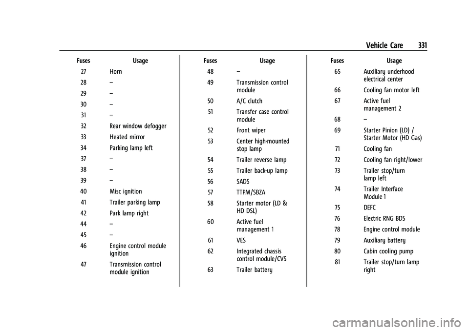
FusesUsage
27 Horn
28 –
29 –
30 –
31 –
32 Rear window defogger
33 Heated mirror
34 Parking lamp left 37 –
38 –
39 –
40 Misc ignition 41 Trailer parking lamp
42 Park lamp right
44 –
45 –
46 Engine control module ignition
47 Transmission control module ignition Fuses
Usage
48 –
49 Transmission control module
50 A/C clutch 51 Transfer case control module
52 Front wiper
53 Center high-mounted stop lamp
54 Trailer reverse lamp 55 Trailer back-up lamp
56 SADS 57 TTPM/SBZA
58 Starter motor (LD & HD DSL)
60 Active fuel management 1
61 VES
62 Integrated chassis control module/CVS
63 Trailer battery Fuses
Usage
65 Auxiliary underhood electrical center
66 Cooling fan motor left 67 Active fuel management 2
68 –
69 Starter Pinion (LD) / Starter Motor (HD Gas)
71 Cooling fan
72 Cooling fan right/lower
73 Trailer stop/turn lamp left
74 Trailer Interface Module 1
75 DEFC
76 Electric RNG BDS
78 Engine control module
79 Auxiliary battery
80 Cabin cooling pump 81 Trailer stop/turn lamp right
Page 333 of 433

Chevrolet Silverado 2500 HD/3500 HD Owner Manual (GMNA-Localizing-U.
S./Canada/Mexico-14632154) - 2021 - CRC - 11/20/20
332 Vehicle Care
FusesUsage
82 Trailer Interface Module 2
83 FTZM
84 Trailer brake 85 ENG
86 Engine control module 87 Injector B even
88 O2 B sensor
89 O2 A sensor
90 Injector A odd 91 Engine control module throttle control
92 Cool fan clutch/ Aeroshutter Relays
Usage
5 Headlamp
18 DC/AC inverter
23 Rear window defogger
35 Parking lamp
36 Run/Crank
43 –
59 A/C clutch
64 Starter Motor (LD & HD DSL)
70 Starter Pinion (LD) / Starter Motor (HD Gas)
77 PowertrainInstrument Panel Fuse Block (Left)
The left instrument panel fuse block access
door is on the driver side edge of the
instrument panel.
The vehicle may not be equipped with all of
the fuses, relays, and features shown.
Pull off the cover to access the fuse block.
A fuse puller is available in the left
instrument panel end cap.
Page 334 of 433
Chevrolet Silverado 2500 HD/3500 HD Owner Manual (GMNA-Localizing-U.
S./Canada/Mexico-14632154) - 2021 - CRC - 11/20/20
Vehicle Care 333
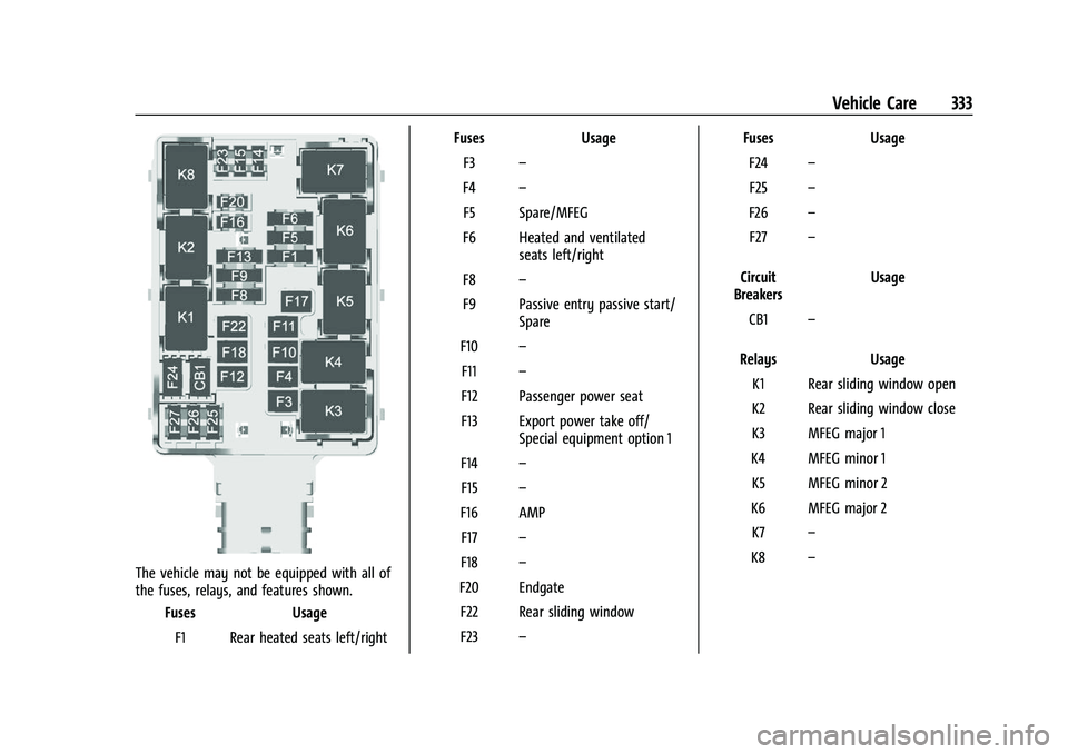
The vehicle may not be equipped with all of
the fuses, relays, and features shown.Fuses Usage
F1 Rear heated seats left/right Fuses
Usage
F3 –
F4 –
F5 Spare/MFEG
F6 Heated and ventilated seats left/right
F8 –
F9 Passive entry passive start/ Spare
F10 –
F11 –
F12 Passenger power seat
F13 Export power take off/ Special equipment option 1
F14 –
F15 –
F16 AMP F17 –
F18 –
F20 Endgate F22 Rear sliding window
F23 – Fuses
Usage
F24 –
F25 –
F26 –
F27 –
Circuit
Breakers Usage
CB1 –
Relays Usage
K1 Rear sliding window open
K2 Rear sliding window close
K3 MFEG major 1
K4 MFEG minor 1 K5 MFEG minor 2
K6 MFEG major 2 K7 –
K8 –
Page 336 of 433
Chevrolet Silverado 2500 HD/3500 HD Owner Manual (GMNA-Localizing-U.
S./Canada/Mexico-14632154) - 2021 - CRC - 11/20/20
Vehicle Care 335
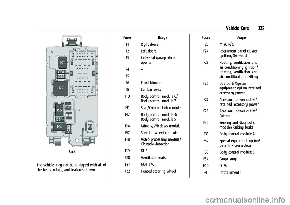
Back
The vehicle may not be equipped with all of
the fuses, relays, and features shown. Fuses Usage
F1 Right doors
F2 Left doors
F3 Universal garage door opener
F4 –
F5 –
F6 Front blower
F8 Lumbar switch
F10 Body control module 6/ Body control module 7
F11 Seat/Column lock module
F12 Body control module 3/ Body control module 5
F14 Mirrors/Windows module F17 Steering wheel controls
F18 Video processing module/ Obstacle detection
F19 DLIS
F20 Ventilated seats F21 NOT R/C
F22 Heated steering wheel Fuses Usage
F23 MISC R/C
F24 Instrument panel cluster ignition/Overhead
F25 Heating, ventilation, and air conditioning ignition/
Heating, ventilation, and
air conditioning auxiliary
F26 USB ports/Special equipment option retained
accessory power
F27 Accessory power outlet/ retained accessory power
F28 Accessory power outlet/ Battery
F30 Sensing and diagnostic module/Parking brake
F31 Body control module 4
F32 Special equipment option/ Data link connection
F33 Body control module 8
F34 Cargo lamp
F40 CGM F41 Infotainment 1
Page 340 of 433
Chevrolet Silverado 2500 HD/3500 HD Owner Manual (GMNA-Localizing-U.
S./Canada/Mexico-14632154) - 2021 - CRC - 11/20/20
Vehicle Care 339
Tire Designations
Tire Size
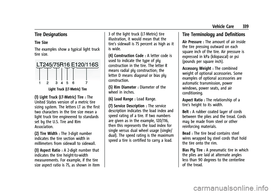
The examples show a typical light truck
tire size.
Light Truck (LT-Metric) Tire
(1) Light Truck (LT-Metric) Tire:The
United States version of a metric tire
sizing system. The letters LT as the first
two characters in the tire size mean a
light truck tire engineered to standards
set by the U.S. Tire and Rim
Association.
(2) Tire Width
:The 3-digit number
indicates the tire section width in
millimeters from sidewall to sidewall.
(3) Aspect Ratio
:A 2-digit number that
indicates the tire height-to-width
measurements. For example, if the tire
size aspect ratio is 75, as shown in item 3 of the light truck (LT-Metric) tire
illustration, it would mean that the
tire's sidewall is 75 percent as high as it
is wide.
(4) Construction Code
:A letter code is
used to indicate the type of ply
construction in the tire. The letter R
means radial ply construction; the
letter D means diagonal or bias ply
construction.
(5) Rim Diameter
:Diameter of the
wheel in inches.
(6) Load Range
:Load Range.
(7) Service Description
:The service
description indicates the load index and
speed rating of a tire. If two numbers
are given as in the example, 120/116,
then this represents the load index for
single versus dual wheel usage (single/
dual). The speed rating is the maximum
speed a tire is certified to carry a load.
Tire Terminology and Definitions
Air Pressure:The amount of air inside
the tire pressing outward on each
square inch of the tire. Air pressure is
expressed in kPa (kilopascal) or psi
(pounds per square inch).
Accessory Weight
:The combined
weight of optional accessories. Some
examples of optional accessories are
automatic transmission, power
windows, power seats, and air
conditioning.
Aspect Ratio
:The relationship of a
tire's height to its width.
Belt
:A rubber coated layer of cords
between the plies and the tread. Cords
may be made from steel or other
reinforcing materials.
Bead
:The tire bead contains steel
wires wrapped by steel cords that hold
the tire onto the rim.
Bias Ply Tire
:A pneumatic tire in which
the plies are laid at alternate angles
less than 90 degrees to the centerline
of the tread.
Page 365 of 433
Chevrolet Silverado 2500 HD/3500 HD Owner Manual (GMNA-Localizing-U.
S./Canada/Mexico-14632154) - 2021 - CRC - 11/20/20
364 Vehicle Care
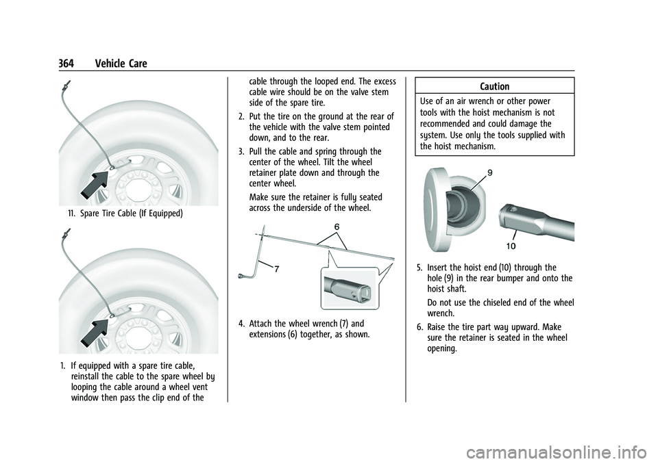
11. Spare Tire Cable (If Equipped)
1. If equipped with a spare tire cable,reinstall the cable to the spare wheel by
looping the cable around a wheel vent
window then pass the clip end of the cable through the looped end. The excess
cable wire should be on the valve stem
side of the spare tire.
2. Put the tire on the ground at the rear of the vehicle with the valve stem pointed
down, and to the rear.
3. Pull the cable and spring through the center of the wheel. Tilt the wheel
retainer plate down and through the
center wheel.
Make sure the retainer is fully seated
across the underside of the wheel.
4. Attach the wheel wrench (7) andextensions (6) together, as shown.
Caution
Use of an air wrench or other power
tools with the hoist mechanism is not
recommended and could damage the
system. Use only the tools supplied with
the hoist mechanism.
5. Insert the hoist end (10) through thehole (9) in the rear bumper and onto the
hoist shaft.
Do not use the chiseled end of the wheel
wrench.
6. Raise the tire part way upward. Make sure the retainer is seated in the wheel
opening.