2021 CHEVROLET SILVERADO 2500HD instrument cluster
[x] Cancel search: instrument clusterPage 248 of 433
Chevrolet Silverado 2500 HD/3500 HD Owner Manual (GMNA-Localizing-U.
S./Canada/Mexico-14632154) - 2021 - CRC - 11/20/20
Driving and Operating 247
Once the vehicle reaches about 40 km/h
(25 mph) or more, press RES+ up briefly. The
vehicle returns to the previously set speed.
Increasing Speed While Using Cruise Control
Do one of the following:
.Press and hold +RES up until the desired
speed is reached, then release it.
.To increase vehicle speed in small
increments, press +RES up briefly. For
each press, the vehicle goes about 1 km/h
(1 mph) faster.
The speedometer reading can be displayed
in either English or metric units. See
Instrument Cluster 0102. The increment
value used depends on the units displayed.
Reducing Speed While Using Cruise Control
Do one of the following:
.Press and hold SET– down until the
desired lower speed is reached, then
release it.
.To slow down in small increments, press
SET– down briefly. For each press, the
vehicle goes about 1 km/h (1 mph) slower.
The speedometer reading can be displayed
in either English or metric units. See
Instrument Cluster 0102. The increment
value used depends on the units displayed. Passing Another Vehicle While Using Cruise
Control
Use the accelerator pedal to increase the
vehicle speed. When you take your foot off
the pedal, the vehicle will slow down to the
previously set cruise speed. While pressing
the accelerator pedal or shortly following
the release to override cruise control, briefly
pressing SET–
will result in cruise control set
to the current vehicle speed.
Using Cruise Control on Hills
How well the cruise control works on hills
depends on the vehicle speed, the load, and
the steepness of the hills. When going up
steep hills, pressing the accelerator pedal
may be necessary to maintain vehicle speed.
While going downhill, cruise braking helps
maintain driver selected speed.
Cruise Grade Braking is enabled when the
vehicle is started and cruise control is active.
It is not enabled in Range Selection Mode.
It assists in maintaining driver selected
speed when driving on downhill grades by
using the engine and transmission to slow
the vehicle. For other forms of descent control, see
Hill
Descent Control (HDC) 0244, Automatic
Transmission 0232, and Tow/Haul Mode
0 235.
Ending Cruise Control
There are four ways to end cruise control:
.Step lightly on the brake pedal.
.Press*.
.Shift the transmission to N (Neutral).
.To turn off cruise control, press5.
Erasing Speed Memory
The cruise control set speed is erased from
memory if
5is pressed or the ignition is
turned off.
Driver Assistance Systems
This vehicle may have features that work
together to help avoid crashes or reduce
crash damage while driving, backing, and
parking. Read this entire section before
using these systems.
Page 257 of 433

Chevrolet Silverado 2500 HD/3500 HD Owner Manual (GMNA-Localizing-U.
S./Canada/Mexico-14632154) - 2021 - CRC - 11/20/20
256 Driving and Operating
.A compatible trailer profile is not
configured or a non-compatible trailer
profile is selected.
.The vehicle is in R (Reverse).
.The trailer is not connected.
.The accessory rear trailer camera is not
connected or connected to the incorrect
input.
The preview may not be provided or the
wrong preview may be provided if:
.The accessory cameras are not recognized.
Ensure that the accessory camera(s) are
connected and power cycle the vehicle.
.The accessory trailer cameras are
swapped at the hitch connector. Ensure
that the accessory camera(s) are
connected to the correct input.
.The accessory trailer camera(s) are
connected to the correct camera input.
.The accessory trailer camera(s) are not
installed according to the installation
instructions.
A feature may be unavailable or not
activating as expected if:
.The customization is disabled. Check the
customization settings where applicable.
.The accessory trailer cameras are
swapped at the hitch connector. Ensure
that the accessory camera(s) are
connected to the correct camera input.
A view may switch automatically if:
.The vehicle is shifted to another gear.
Park Assist
With Front and Rear Park Assist, as the
vehicle moves at speeds of less than 8 km/h
(5 mph) the sensors on the bumpers may
detect objects up to 1.2 m (4 ft) in front and
2.5 m (8 ft) behind the vehicle within a zone
25 cm (10 in) high off the ground and below
bumper level. These detection distances may
be shorter during warmer or humid weather.
Blocked sensors will not detect objects and
can also cause false detections. Keep the
sensors clean of mud, dirt, snow, ice, and
slush; and clean sensors after a car wash in
freezing temperatures.
{Warning
The Park Assist system does not detect
children, pedestrians, bicyclists, animals,
or objects located below the bumper or
that are too close or too far from the
vehicle. It is not available at speeds (Continued)
Warning (Continued)
greater than 8 km/h (5 mph). To prevent
injury, death, or vehicle damage, even
with Park Assist, always check the area
around the vehicle and check all mirrors
before moving forward or backing.
The instrument cluster may have a Park
Assist display with bars that show “distance
to object” and object location information
for the Front and Rear Park Assist system.
As the object gets closer, more bars light up
and the bars change color from yellow to
amber to red.
When an object is first detected in the rear,
one beep will be heard from the rear,
or both sides of the Safety Alert Seat will
pulse two times. When an object is very
close —<0.4 m (1.5 ft) in the vehicle rear or
Page 282 of 433
Chevrolet Silverado 2500 HD/3500 HD Owner Manual (GMNA-Localizing-U.
S./Canada/Mexico-14632154) - 2021 - CRC - 11/20/20
Driving and Operating 281
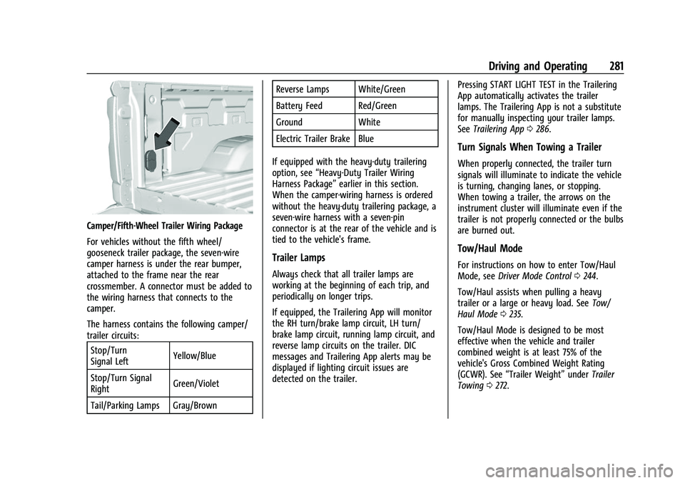
Camper/Fifth-Wheel Trailer Wiring Package
For vehicles without the fifth wheel/
gooseneck trailer package, the seven-wire
camper harness is under the rear bumper,
attached to the frame near the rear
crossmember. A connector must be added to
the wiring harness that connects to the
camper.
The harness contains the following camper/
trailer circuits:Stop/Turn
Signal Left Yellow/Blue
Stop/Turn Signal
Right Green/Violet
Tail/Parking Lamps Gray/Brown Reverse Lamps White/Green
Battery Feed Red/Green
Ground White
Electric Trailer Brake Blue
If equipped with the heavy-duty trailering
option, see “Heavy-Duty Trailer Wiring
Harness Package” earlier in this section.
When the camper-wiring harness is ordered
without the heavy-duty trailering package, a
seven-wire harness with a seven-pin
connector is at the rear of the vehicle and is
tied to the vehicle's frame.
Trailer Lamps
Always check that all trailer lamps are
working at the beginning of each trip, and
periodically on longer trips.
If equipped, the Trailering App will monitor
the RH turn/brake lamp circuit, LH turn/
brake lamp circuit, running lamp circuit, and
reverse lamp circuits on the trailer. DIC
messages and Trailering App alerts may be
displayed if lighting circuit issues are
detected on the trailer. Pressing START LIGHT TEST in the Trailering
App automatically activates the trailer
lamps. The Trailering App is not a substitute
for manually inspecting your trailer lamps.
See
Trailering App 0286.
Turn Signals When Towing a Trailer
When properly connected, the trailer turn
signals will illuminate to indicate the vehicle
is turning, changing lanes, or stopping.
When towing a trailer, the arrows on the
instrument cluster will illuminate even if the
trailer is not properly connected or the bulbs
are burned out.
Tow/Haul Mode
For instructions on how to enter Tow/Haul
Mode, see Driver Mode Control 0244.
Tow/Haul assists when pulling a heavy
trailer or a large or heavy load. See Tow/
Haul Mode 0235.
Tow/Haul Mode is designed to be most
effective when the vehicle and trailer
combined weight is at least 75% of the
vehicle's Gross Combined Weight Rating
(GCWR). See “Trailer Weight” underTrailer
Towing 0272.
Page 286 of 433
Chevrolet Silverado 2500 HD/3500 HD Owner Manual (GMNA-Localizing-U.
S./Canada/Mexico-14632154) - 2021 - CRC - 11/20/20
Driving and Operating 285
ignition back on. If either of these messages
continues, either the vehicle or trailer needs
service.
A GM dealer may be able to diagnose and
repair problems with the trailer. However,
any diagnosis and repair of the trailer is not
covered under the vehicle warranty. Contact
your trailer dealer for assistance with trailer
repairs and trailer warranty information.
Trailer Sway Control (TSC)
Vehicles with StabiliTrak/Electronic Stability
Control (ESC) have a Trailer Sway Control
(TSC) feature. Trailer sway is unintended
side-to-side motion of a trailer while towing.
If the vehicle is towing a trailer and the TSC
detects that sway is increasing, the vehicle
brakes are selectively applied at each wheel,
to help reduce excessive trailer sway.
If equipped with the Integrated Trailer Brake
Control (ITBC) system, and the trailer has an
electric brake system, StabiliTrak/ESC may
also apply the trailer brakes.
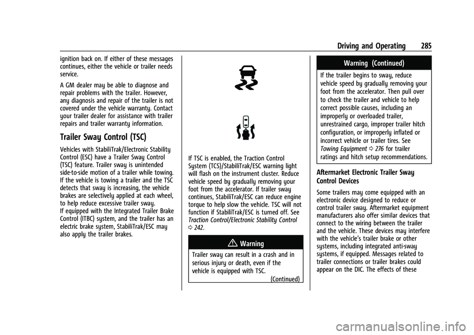
If TSC is enabled, the Traction Control
System (TCS)/StabiliTrak/ESC warning light
will flash on the instrument cluster. Reduce
vehicle speed by gradually removing your
foot from the accelerator. If trailer sway
continues, StabiliTrak/ESC can reduce engine
torque to help slow the vehicle. TSC will not
function if StabiliTrak/ESC is turned off. See
Traction Control/Electronic Stability Control
0242.
{Warning
Trailer sway can result in a crash and in
serious injury or death, even if the
vehicle is equipped with TSC.
(Continued)
Warning (Continued)
If the trailer begins to sway, reduce
vehicle speed by gradually removing your
foot from the accelerator. Then pull over
to check the trailer and vehicle to help
correct possible causes, including an
improperly or overloaded trailer,
unrestrained cargo, improper trailer hitch
configuration, or improperly inflated or
incorrect vehicle or trailer tires. See
Towing Equipment0276 for trailer
ratings and hitch setup recommendations.
Aftermarket Electronic Trailer Sway
Control Devices
Some trailers may come equipped with an
electronic device designed to reduce or
control trailer sway. Aftermarket equipment
manufacturers also offer similar devices that
connect to the wiring between the trailer
and the vehicle. These devices may interfere
with the vehicle’s trailer brake or other
systems, including integrated anti-sway
systems, if equipped. Messages related to
trailer connections or trailer brakes could
appear on the DIC. The effects of these
Page 313 of 433
Chevrolet Silverado 2500 HD/3500 HD Owner Manual (GMNA-Localizing-U.
S./Canada/Mexico-14632154) - 2021 - CRC - 11/20/20
312 Vehicle Care
{Warning
Steam and scalding liquids from a hot
cooling system are under pressure.
Turning the pressure cap, even a little,
can cause them to come out at high
speed and you could be burned. Never
turn the cap when the cooling system,
including the pressure cap, is hot. Wait
for the cooling system and pressure cap
to cool.
Caution
Failure to follow the specific coolant fill
procedure could cause the engine to
overheat and could cause system
damage. If coolant is not visible in the
surge tank, contact your dealer.
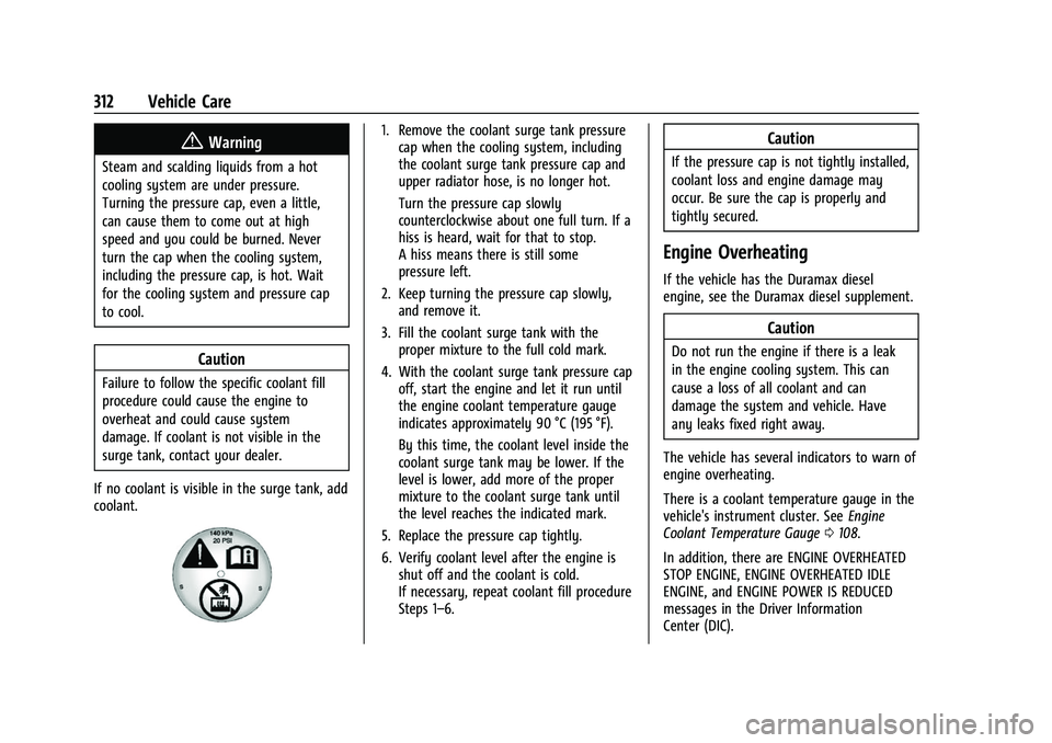
If no coolant is visible in the surge tank, add
coolant.
1. Remove the coolant surge tank pressure cap when the cooling system, including
the coolant surge tank pressure cap and
upper radiator hose, is no longer hot.
Turn the pressure cap slowly
counterclockwise about one full turn. If a
hiss is heard, wait for that to stop.
A hiss means there is still some
pressure left.
2. Keep turning the pressure cap slowly, and remove it.
3. Fill the coolant surge tank with the proper mixture to the full cold mark.
4. With the coolant surge tank pressure cap off, start the engine and let it run until
the engine coolant temperature gauge
indicates approximately 90 °C (195 °F).
By this time, the coolant level inside the
coolant surge tank may be lower. If the
level is lower, add more of the proper
mixture to the coolant surge tank until
the level reaches the indicated mark.
5. Replace the pressure cap tightly.
6. Verify coolant level after the engine is shut off and the coolant is cold.
If necessary, repeat coolant fill procedure
Steps 1–6.Caution
If the pressure cap is not tightly installed,
coolant loss and engine damage may
occur. Be sure the cap is properly and
tightly secured.
Engine Overheating
If the vehicle has the Duramax diesel
engine, see the Duramax diesel supplement.
Caution
Do not run the engine if there is a leak
in the engine cooling system. This can
cause a loss of all coolant and can
damage the system and vehicle. Have
any leaks fixed right away.
The vehicle has several indicators to warn of
engine overheating.
There is a coolant temperature gauge in the
vehicle's instrument cluster. See Engine
Coolant Temperature Gauge 0108.
In addition, there are ENGINE OVERHEATED
STOP ENGINE, ENGINE OVERHEATED IDLE
ENGINE, and ENGINE POWER IS REDUCED
messages in the Driver Information
Center (DIC).
Page 336 of 433
Chevrolet Silverado 2500 HD/3500 HD Owner Manual (GMNA-Localizing-U.
S./Canada/Mexico-14632154) - 2021 - CRC - 11/20/20
Vehicle Care 335
Back
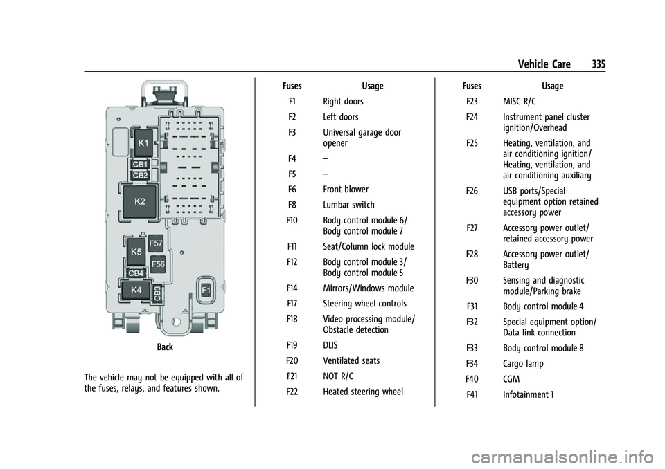
The vehicle may not be equipped with all of
the fuses, relays, and features shown. Fuses Usage
F1 Right doors
F2 Left doors
F3 Universal garage door opener
F4 –
F5 –
F6 Front blower
F8 Lumbar switch
F10 Body control module 6/ Body control module 7
F11 Seat/Column lock module
F12 Body control module 3/ Body control module 5
F14 Mirrors/Windows module F17 Steering wheel controls
F18 Video processing module/ Obstacle detection
F19 DLIS
F20 Ventilated seats F21 NOT R/C
F22 Heated steering wheel Fuses Usage
F23 MISC R/C
F24 Instrument panel cluster ignition/Overhead
F25 Heating, ventilation, and air conditioning ignition/
Heating, ventilation, and
air conditioning auxiliary
F26 USB ports/Special equipment option retained
accessory power
F27 Accessory power outlet/ retained accessory power
F28 Accessory power outlet/ Battery
F30 Sensing and diagnostic module/Parking brake
F31 Body control module 4
F32 Special equipment option/ Data link connection
F33 Body control module 8
F34 Cargo lamp
F40 CGM F41 Infotainment 1
Page 337 of 433
Chevrolet Silverado 2500 HD/3500 HD Owner Manual (GMNA-Localizing-U.
S./Canada/Mexico-14632154) - 2021 - CRC - 11/20/20
336 Vehicle Care
FusesUsage
F42 TCP
F43 –
F44 Active vibration management
F45 Body control module 2
F46 Heating, ventilation, and air conditioning/Battery 1
F47 Instrument panel cluster/ Battery
F48 Transmission control module
F49 Body control module 1 F50 –
F51 Battery 1
F52 Battery 2
F53 –
F54 Sunroof F55 Driver power seat
F56 DC DC TRANS 1 F57 DC DC TRANS 2
F58 Infotainment 2 Circuit
Breakers Usage
1 Accessory power outlet 2
2 Accessory power outlet 1/ Cigarette Lighter
3 Accessory power outlet 3
4 Accessory power outlet 4
Relays Usage
K1 Run/Crank
K2 Retained accessory power/ Accessory 1
K4 Retained accessory power/ Accessory 2
K5 –
Wheels and Tires
Tires
Every new GM vehicle has high-quality
tires made by a leading tire
manufacturer. See the warranty manual
for information regarding the tire warranty and where to get service. For
additional information refer to the tire
manufacturer.
{Warning
.Poorly maintained and improperly
used tires are dangerous.
.Overloading the tires can cause
overheating as a result of too
much flexing. There could be a
blowout and a serious crash. See
Vehicle Load Limits
0217.
.Underinflated tires pose the same
danger as overloaded tires. The
resulting crash could cause serious
injury. Check all tires frequently to
maintain the recommended
pressure. Tire pressure should be
checked when the tires are cold.
.Overinflated tires are more likely
to be cut, punctured, or broken by
a sudden impact —such as when
hitting a pothole. Keep tires at the
recommended pressure.
(Continued)
Page 344 of 433

Chevrolet Silverado 2500 HD/3500 HD Owner Manual (GMNA-Localizing-U.
S./Canada/Mexico-14632154) - 2021 - CRC - 11/20/20
Vehicle Care 343
As an added safety feature, your vehicle has
been equipped with a tire pressure
monitoring system (TPMS) that illuminates a
low tire pressure telltale when one or more
of your tires is significantly under-inflated.
Accordingly, when the low tire pressure
telltale illuminates, you should stop and
check your tires as soon as possible, and
inflate them to the proper pressure. Driving
on a significantly under-inflated tire causes
the tire to overheat and can lead to tire
failure. Under-inflation also reduces fuel
efficiency and tire tread life, and may affect
the vehicle's handling and stopping ability.
Please note that the TPMS is not a
substitute for proper tire maintenance, and
it is the driver's responsibility to maintain
correct tire pressure, even if under-inflation
has not reached the level to trigger
illumination of the TPMS low tire pressure
telltale.
Your vehicle has also been equipped with a
TPMS malfunction indicator to indicate when
the system is not operating properly. The
TPMS malfunction indicator is combined
with the low tire pressure telltale. When the
system detects a malfunction, the telltale
will flash for approximately one minute and
then remain continuously illuminated. Thissequence will continue upon subsequent
vehicle start-ups as long as the malfunction
exists.
When the malfunction indicator is
illuminated, the system may not be able to
detect or signal low tire pressure as
intended. TPMS malfunctions may occur for
a variety of reasons, including the
installation of replacement or alternate tires
or wheels on the vehicle that prevent the
TPMS from functioning properly. Always
check the TPMS malfunction telltale after
replacing one or more tires or wheels on
your vehicle to ensure that the replacement
or alternate tires and wheels allow the
TPMS to continue to function properly.
See
Tire Pressure Monitor Operation 0343.
See Radio Frequency Statement 0409.
Tire Pressure Monitor Operation
This vehicle may have a Tire Pressure
Monitor System (TPMS). The TPMS is
designed to warn the driver when a low tire
pressure condition exists. TPMS sensors are
mounted onto each tire and wheel
assembly, excluding the spare tire and
wheel assembly. The TPMS sensors monitor the air pressure in the tires and transmit the
tire pressure readings to a receiver located
in the vehicle.
When a low tire pressure condition is
detected, the TPMS illuminates the low tire
pressure warning light located on the
instrument cluster. If the warning light
comes on, stop as soon as possible and
inflate the tires to the recommended
pressure shown on the Tire and Loading
Information label. See
Vehicle Load Limits
0 217.
A message to check the pressure in a
specific tire displays in the Driver
Information Center (DIC). The low tire
pressure warning light and the DIC warning
message come on at each ignition cycle
until the tires are inflated to the correct
inflation pressure. If the vehicle has DIC
buttons, tire pressure levels can be
viewed. For additional information and
details about the DIC operation and