2021 CHEVROLET SILVERADO 2500HD height
[x] Cancel search: heightPage 131 of 433
Chevrolet Silverado 2500 HD/3500 HD Owner Manual (GMNA-Localizing-U.
S./Canada/Mexico-14632154) - 2021 - CRC - 11/20/20
130 Instruments and Controls
Automatic Running Boards
This feature specifies the position and use of
the running boards.
Touch Off or On.
Deploy Running Boards
This feature moves the running boards to a
deployed position so they can be used with
the doors closed.
Touch Off or Deploy.
Seating Position
Touch and the following may display:
.Seat Entry Memory
.Seat Exit Memory
Seat Entry Memory
This feature automatically recalls the
previously stored 1 or 2 button positions
when the ignition is changed from off to on
or ACC/ACCESSORY. See Memory Seats046.
Touch Off or On. Seat Exit Memory
This feature automatically recalls the
previously stored exit button position when
the ignition is changed from on or ACC/
ACCESSORY to off and the driver door is
open. See
Memory Seats 046.
Touch Off or On.
Suspension
Touch and the following may display:
.Service Mode
.Alignment Mode
Service Mode
This feature disables the air suspension
system and is used to prevent unintended
raising or lowering of the suspension..
Touch Off or On.
Alignment Mode
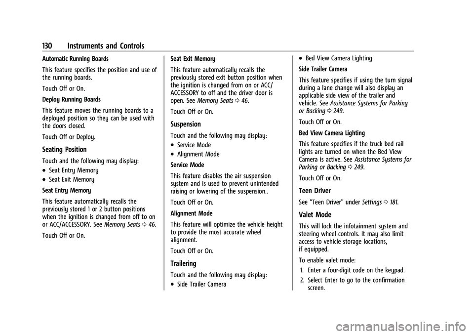
This feature will optimize the vehicle height
to provide the most accurate wheel
alignment.
Touch Off or On.
Trailering
Touch and the following may display:
.Side Trailer Camera
.Bed View Camera Lighting
Side Trailer Camera
This feature specifies if using the turn signal
during a lane change will also display an
applicable side view of the trailer and
vehicle. See Assistance Systems for Parking
or Backing 0249.
Touch Off or On.
Bed View Camera Lighting
This feature specifies if the truck bed rail
lights are turned on when the Bed View
Camera is active. See Assistance Systems for
Parking or Backing 0249.
Touch Off or On.
Teen Driver
See “Teen Driver” underSettings 0181.
Valet Mode
This will lock the infotainment system and
steering wheel controls. It may also limit
access to vehicle storage locations,
if equipped.
To enable valet mode:
1. Enter a four-digit code on the keypad.
2. Select Enter to go to the confirmation screen.
Page 222 of 433
Chevrolet Silverado 2500 HD/3500 HD Owner Manual (GMNA-Localizing-U.
S./Canada/Mexico-14632154) - 2021 - CRC - 11/20/20
Driving and Operating 221
There is also important loading
information for off-road driving in this
manual. See“Loading the Vehicle for
Off-Road Driving“ underOff-Road
Driving 0211.
Two-Tiered Loading
Depending on the model of the pickup,
an upper load platform can be created
by positioning three or four 5 cm (2 in)
by 15 cm (6 in) wooden planks across
the width of the pickup box. The planks
must be inserted in the pickup box
depressions.
When using this upper load platform,
be sure the load is securely tied down
to prevent it from shifting. The load's
center of gravity should be positioned
in a zone over the rear axle. The zone is
located in the area between the front
of each wheel well and the rear of each
wheel well. The center of gravity height
must not extend above the top of the
pickup box flareboard. Any load that extends beyond the
vehicle's taillamp area must be properly
marked according to local laws and
regulations.
Remember not to exceed the Gross Axle
Weight Rating (GAWR) of the front or
rear axle.
Add-On Equipment
When carrying removable items, a limit
on how many people carried inside the
vehicle may be necessary. Be sure to
weigh the vehicle before buying and
installing the new equipment.
Caution
Overloading the vehicle may cause
damage. Repairs would not be covered by
the vehicle warranty. Do not overload the
vehicle.
Remember not to exceed the Gross Axle
Weight Rating (GAWR) of the front or
rear axle. * Equipment Maximum Weight
Ladder Rack and
Cargo
340 kg (750 lb)
Cross Toolbox and
Cargo 181 kg (400 lb)
Side Boxes and
Cargo 113 kg per side
(250 lb per side)
* The combined weight for all
rail-mounted equipment should not
exceed 454 kg (1,000 lb).
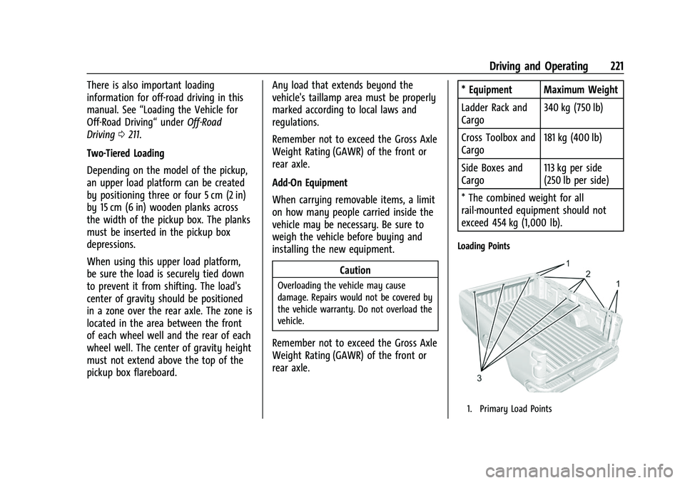
Loading Points
1. Primary Load Points
Page 246 of 433
Chevrolet Silverado 2500 HD/3500 HD Owner Manual (GMNA-Localizing-U.
S./Canada/Mexico-14632154) - 2021 - CRC - 11/20/20
Driving and Operating 245
Modes:
Normal Mode :Use for normal city and
highway driving to provide a smooth ride.
This setting provides balance between
comfort and handling. This is the standard/
default mode. There is no persistent
indicator in the instrument cluster for
this mode.
6Snow/Ice Mode : Snow/Ice Mode
improves vehicle acceleration on snow and
ice covered roads. When active, Snow/Ice
Mode will adjust acceleration to optimize
traction on slippery surfaces. This can
compromise the acceleration on dry asphalt.
This feature is not intended for use when
the vehicle is stuck in sand, mud, ice, snow,
or gravel. If the vehicle becomes stuck, see If
the Vehicle Is Stuck 0216.
7Off-Road Mode : Use this mode for
off-road recreational driving. Off-Road Mode
should be used to improve driving at
moderate speeds, on grass, gravel, dirt,
unpaved roads, or snow-covered roads. The
accelerator pedal is tuned for off-road use.
This mode modifies pedal mapping,
All-Wheel Drive (AWD), ride height, Antilock Brake System (ABS), StabiliTrak/Electronic
Stability Control (ESC), and Traction Control
System (TCS) performance.
For more information on off-road driving see
Off-Road Driving
0211.
_Tow/Haul Mode : Use this mode
when hauling heavy loads to provide
increased performance and vehicle control.
Tow/Haul Mode adjusts the transmission
shift pattern, AWD, and ESC performance.
If the vehicle is turned off with Tow/Haul
Mode active and then restarted within four
hours or less, Tow/Haul will remain active.
Otherwise, the vehicle will start in
Normal Mode.
If the vehicle has a diesel engine, exhaust
braking is automatically activated when
Tow/Haul Mode is selected. It maintains
vehicle speed by automatically
implementing a shift pattern that uses the
engine and the transmission to slow the
vehicle. The system will command
downshifts and use the turbocharger on the
engine to reduce vehicle speed when the
brake is applied. The normal tow/haul shift
pattern will return once the vehicle is on a
low grade or when the accelerator pedal is
pressed. While in the Electronic Range Select (ERS)
Mode (see
“manual mode”), grade breaking
is deactivated, allowing the driver to select a
range and limiting the highest gear
available.
For more information on trailer weight
specifications, see Towing Equipment 0276.
Limited-Slip Differential
If equipped, the limited-slip differential can
give more traction on snow, mud, ice, sand,
or gravel. It works like a standard axle most
of the time, but when traction is low, this
feature allows the drive wheel with the
most traction to move the vehicle. For
vehicles with the limited-slip differential,
driven under severe conditions, the rear axle
fluid should be changed. See Maintenance
Schedule 0384.
Locking Rear Axle
Vehicles with a locking rear axle can give
more traction on snow, mud, ice, sand,
or gravel. It works like a standard axle most
of the time, but when traction is low, this
feature will allow the rear wheel with the
most traction to move the vehicle.
Page 262 of 433

Chevrolet Silverado 2500 HD/3500 HD Owner Manual (GMNA-Localizing-U.
S./Canada/Mexico-14632154) - 2021 - CRC - 11/20/20
Driving and Operating 261
part of the Lane Change Alert (LCA) system,
read the entire LCA section before using this
feature.
Lane Change Alert (LCA)
If equipped, the LCA system is a
lane-changing aid that assists drivers with
avoiding lane change crashes that occur with
moving vehicles in the side blind zone (or
spot) areas or with vehicles rapidly
approaching these areas from behind. The
LCA warning display will light up in the
corresponding outside side mirror and will
flash if the turn signal is on.
{Warning
LCA does not alert the driver to vehicles
outside of the system detection zones,
pedestrians, bicyclists, or animals. It may
not provide alerts when changing lanes
under all driving conditions. Failure to use
proper care when changing lanes may
result in injury, death, or vehicle damage.
Before making a lane change, always
check mirrors, glance over your shoulder,
and use the turn signals.LCA Detection Zones
1. SBZA Detection Zone
2. LCA Detection Zone
The LCA sensor covers a zone of
approximately one lane over from both
sides of the vehicle, or 3.5 m (11 ft). The
height of the zone is approximately between
0.5 m (1.5 ft) and 2 m (6 ft) off the ground.
The Side Blind Zone Alert (SBZA) warning
area starts at approximately the middle of
the vehicle and goes back 5 m (16 ft). Drivers
are also warned of vehicles rapidly
approaching from up to 70 m (230 ft) behind
the vehicle.
How the System Works
The LCA symbol lights up in the side mirrors
when the system detects a moving vehicle
in the next lane over that is in the side blind zone or rapidly approaching that zone
from behind. A lit LCA symbol indicates it
may be unsafe to change lanes. Before
making a lane change, check the LCA
display, check mirrors, glance over your
shoulder, and use the turn signals.
Left Side Mirror
DisplayRight Side Mirror Display
When the vehicle is started, both outside
mirror LCA displays will briefly come on to
indicate the system is operating. When the
vehicle is in a forward gear, the left or right
side mirror display will light up if a moving
vehicle is detected in the next lane over in
that blind zone or rapidly approaching that
zone. If the turn signal is activated in the
same direction as a detected vehicle, this
display will flash as an extra warning not to
change lanes.
Page 278 of 433
Chevrolet Silverado 2500 HD/3500 HD Owner Manual (GMNA-Localizing-U.
S./Canada/Mexico-14632154) - 2021 - CRC - 11/20/20
Driving and Operating 277
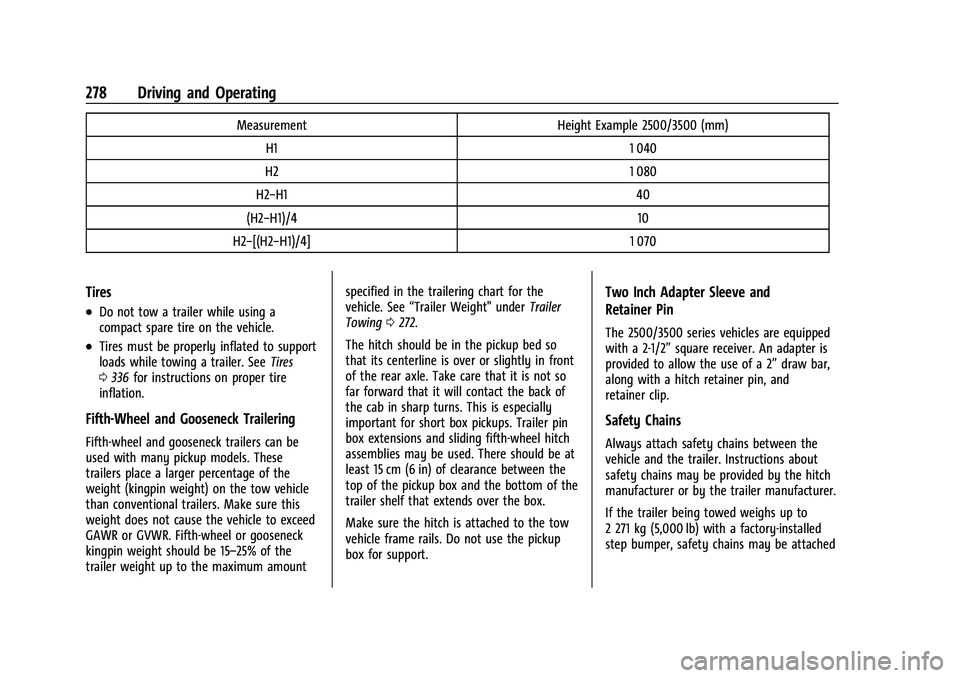
Weight-Distributing Hitch and Adjustment
A weight-distributing hitch may be useful with some trailers. Use the following guidelines to determine if a weight-distributing hitch should
be used.Vehicle Maximum Trailer Weight GCWR* Maximum Tongue Weight
2500/3500 Up to 9 080 kg (20,000 lb) See (1) below 25%
(1) Weight distributing hitch required on vehicles equipped with On/Off Road (OOR) and Mud Terrain (MT) tires with trailers over 10,000 lbs.
Weight distributing hitch optional for other vehicles.
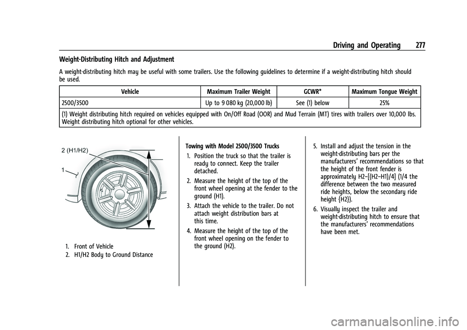
1. Front of Vehicle
2. H1/H2 Body to Ground Distance
Towing with Model 2500/3500 Trucks 1. Position the truck so that the trailer is ready to connect. Keep the trailer
detached.
2. Measure the height of the top of the front wheel opening at the fender to the
ground (H1).
3. Attach the vehicle to the trailer. Do not attach weight distribution bars at
this time.
4. Measure the height of the top of the front wheel opening on the fender to
the ground (H2). 5. Install and adjust the tension in the
weight-distributing bars per the
manufacturers’ recommendations so that
the height of the front fender is
approximately H2−[(H2−H1)/4] (1/4 the
difference between the two measured
ride heights, below the secondary ride
height {H2}).
6. Visually inspect the trailer and weight-distributing hitch to ensure that
the manufacturers’ recommendations
have been met.
Page 279 of 433
Chevrolet Silverado 2500 HD/3500 HD Owner Manual (GMNA-Localizing-U.
S./Canada/Mexico-14632154) - 2021 - CRC - 11/20/20
278 Driving and Operating
MeasurementHeight Example 2500/3500 (mm)
H1 1 040
H2 1 080
H2−H1 40
(H2−H1)/4 10
H2−[(H2−H1)/4] 1 070
Tires
.Do not tow a trailer while using a
compact spare tire on the vehicle.
.Tires must be properly inflated to support
loads while towing a trailer. SeeTires
0 336 for instructions on proper tire
inflation.
Fifth-Wheel and Gooseneck Trailering
Fifth-wheel and gooseneck trailers can be
used with many pickup models. These
trailers place a larger percentage of the
weight (kingpin weight) on the tow vehicle
than conventional trailers. Make sure this
weight does not cause the vehicle to exceed
GAWR or GVWR. Fifth-wheel or gooseneck
kingpin weight should be 15–25% of the
trailer weight up to the maximum amount specified in the trailering chart for the
vehicle. See
“Trailer Weight" under Trailer
Towing 0272.
The hitch should be in the pickup bed so
that its centerline is over or slightly in front
of the rear axle. Take care that it is not so
far forward that it will contact the back of
the cab in sharp turns. This is especially
important for short box pickups. Trailer pin
box extensions and sliding fifth-wheel hitch
assemblies may be used. There should be at
least 15 cm (6 in) of clearance between the
top of the pickup box and the bottom of the
trailer shelf that extends over the box.
Make sure the hitch is attached to the tow
vehicle frame rails. Do not use the pickup
box for support.
Two Inch Adapter Sleeve and
Retainer Pin
The 2500/3500 series vehicles are equipped
with a 2-1/2” square receiver. An adapter is
provided to allow the use of a 2” draw bar,
along with a hitch retainer pin, and
retainer clip.
Safety Chains
Always attach safety chains between the
vehicle and the trailer. Instructions about
safety chains may be provided by the hitch
manufacturer or by the trailer manufacturer.
If the trailer being towed weighs up to
2 271 kg (5,000 lb) with a factory-installed
step bumper, safety chains may be attached
Page 290 of 433

Chevrolet Silverado 2500 HD/3500 HD Owner Manual (GMNA-Localizing-U.
S./Canada/Mexico-14632154) - 2021 - CRC - 11/20/20
Driving and Operating 289
4. Move to the next tire and repeat Step 3for each sensor. The horn chirps twice
when all sensors are completed.
5. Return to the vehicle to complete the setup.
Maintenance Reminders
To set up maintenance reminders, touch the
Trailer Maintenance icon. Select Yes to set
up the maintenance reminders for the
Trailer Profile. Follow the on-screen prompts.
The maximum number of reminders is 50.
Select No to return to the previous screen.
Towing Assistance
To set up towing assistance features,
if equipped, touch the Towing
Assistance icon.
Touch Yes to begin set up or touch No to
return to the previous screen.
1. Select the number of axles on the trailer.
2. Enter trailer dimensions as prompted.
3. Follow the on-screen instructions to complete setup for available features.
Transparent Trailer Setup (if equipped)
To complete setup for transparent trailer:
.Trailer Length: 300 cm (118.1 in) –970 cm
(381.8 in). Measure from center of coupler
to furthest rear point on the trailer.
.Trailer Width: 120 cm (47.2 in) –260 cm
(102.3 in). Measure from left edge to
right edge.
.Trailer Height: 1 cm (0.39 in) –450 cm
(177.1 in). Measure from ground to tallest
point.
.Hitching Point Length: 180 cm (70.8 in) –
970 cm (381.8 in). Measure from center of
coupler to middle of tires.
.Trailer Tongue Length: 50 cm (19.6 in) –
220 cm (86.6 in). Measure from center of
coupler to trailer front wall.
.Vehicle Hitch Height: 10 cm (3.9 in) –
100 cm (39.3 in). Measure from ground to
top of coupler.
.Vehicle Hitch Length: 10 cm (3.9 in) –
100 cm (39.3 in). Measure from hitch
receiver to center of ball.
1. If trailer dimensions are out of range, this feature will be unavailable.
2. Ensure rear trailer camera is connected.
3. Follow instructions to drive forward to complete calibration.
Rear Trailer Guidance Setup (if equipped)
A rear trailer camera must be mounted on
the trailer and electrically connected to the
vehicle before transparent trailer feature can
be used. See Assistance Systems for Parking
or Backing 0249.
Trailer dimensions must be in range to
enable this feature.
.Trailer Length: 300 cm (118.1 in) –970 cm
(381.8 in). Measure from center of coupler
to furthest rear point on the trailer.
1. If trailer dimensions are out of range, this feature will be unavailable.
2. Ensure rear trailer camera is connected.
3. Follow instructions to drive forward to complete calibration.
Jack-Knife Alert Setup (if equipped)
Follow instructions to drive forward to
complete calibration.
Trailer Length Indicator Setup (if
equipped)
Follow instructions to drive forward to
complete calibration.
Page 303 of 433
Chevrolet Silverado 2500 HD/3500 HD Owner Manual (GMNA-Localizing-U.
S./Canada/Mexico-14632154) - 2021 - CRC - 11/20/20
302 Vehicle Care
Accessories and Modifications
Adding non-dealer accessories or making
modifications to the vehicle can affect
vehicle performance and safety, including
such things as airbags, braking, stability,
ride and handling, emissions systems,
aerodynamics, durability, and electronic
systems like antilock brakes, traction control,
and stability control. These accessories or
modifications could even cause malfunction
or damage not covered by the vehicle
warranty.
Damage to suspension components caused
by modifying vehicle height outside of
factory settings will not be covered by the
vehicle warranty.
Damage to vehicle components resulting
from modifications or the installation or use
of non-GM certified parts, including control
module or software modifications, is not
covered under the terms of the vehicle
warranty and may affect remaining
warranty coverage for affected parts.
GM Accessories are designed to complement
and function with other systems on the
vehicle. See your dealer to accessorize the
vehicle using genuine GM Accessories
installed by a dealer technician.Also, see
Adding Equipment to the
Airbag-Equipped Vehicle 066.
Vehicle Checks
Doing Your Own Service Work
{Warning
It can be dangerous to work on your
vehicle if you do not have the proper
knowledge, service manual, tools,
or parts. Always follow owner’s manual
procedures and consult the service
manual for your vehicle before doing any
service work.
If doing some of your own service work, use
the proper service manual. It tells you much
more about how to service the vehicle than
this manual can. To order the proper service
manual, see Publication Ordering
Information 0408.
This vehicle has an airbag system. Before
attempting to do your own service work,
see Servicing the Airbag-Equipped Vehicle
0 66. If equipped with remote vehicle start, open
the hood before performing any service
work to prevent remote starting the vehicle
accidentally. See
Remote Vehicle Start 020.
Keep a record with all parts receipts and list
the mileage and the date of any service
work performed. See Maintenance Records
0 396.Caution
Even small amounts of contamination can
cause damage to vehicle systems. Do not
allow contaminants to contact the fluids,
reservoir caps, or dipsticks.
Hood
{Warning
Turn the vehicle off before opening the
hood. If the engine is running with the
hood open, you or others could be
injured.