2021 CHEVROLET SILVERADO 2500HD buttons
[x] Cancel search: buttonsPage 159 of 433
Chevrolet Silverado 2500 HD/3500 HD Owner Manual (GMNA-Localizing-U.
S./Canada/Mexico-14632154) - 2021 - CRC - 11/20/20
158 Infotainment System
details, and system limitations. Service and
connectivity may vary by make, model,
year, carrier, availability, and conditions.
4G LTE service is available in select markets.
4G LTE performance is based on industry
averages and vehicle systems design. Some
services require a data plan.
The OnStar App
If equipped, the infotainment system has
OnStar controls in the embedded OnStar app
on the Home Page. Most OnStar functions
that can be performed with the buttons can
be done using the app. To open the app,
touch the OnStar icon on the Home Page.
App updates require a corresponding service
plan. Features vary by region and model.
Features are subject to change. For more
information, see my.chevrolet.com/learn or
press
Q.
Services
The Services tab displays the default view
for the app. Use this page to launch the
available OnStar services. Touch a service to
open its display. Touch Wi-Fi to launch the
connections manager. Turn-by-Turn and
Advisor Call are the other tiled options. Account
The Account tab displays a snapshot of the
account linked with the vehicle. If there is
no such account, this tab will show all
values as
——. The advisor call icon will be
active even if there is no active account.
Advisor Call
Selecting Advisor Call is the same as
pressing
Qor calling 1-888-4ONSTAR
(1-888-466-7827). The X option in the upper
right corner of the screen does not end the
call, but returns to the previous screen.
Turn-by-Turn Directions
With a connected plan, an OnStar Advisor
can download a destination to the vehicle or
its embedded navigation system,
if equipped. Select Turn-by-Turn Directions
from the Services tab of the OnStar app to
call an Advisor or select a recent or favorite
destination. Touch the navigation icons to
select home, address or place. A destination
transfer from OnStar will show the detail
view of the destination when it is
transferred from OnStar to the Navigation
application. See www.onstar.com for a
coverage map. Services vary by model. Map
coverage is available in the United States,
Puerto Rico, and Canada. Wi-Fi Hotspot
Touch to display the Settings page, which
shows the configurations for the vehicle
hotspot and allows them to be changed.
For more information, see www.onstar.com.
Navigation
Using the Navigation System
If equipped, launch the Nav application by
touching the Nav icon on the Home Page or
on the shortcut tray near the bottom of the
infotainment display.
When the Nav application is launched for
the first time, a product walkthrough is
available. Use of the feature requires the
Terms and Conditions and the Privacy
statement to be confirmed. If available and
signed into a profile, it is also suggested to
enable and confirm Predictive Navigation.
Predictive Navigation (If Equipped)
If Predictive Navigation is available and
confirmed, this feature learns preferences by
remembering where the vehicle has been.
It uses the locations and navigation history
to personalize routes and results.
Page 203 of 433

Chevrolet Silverado 2500 HD/3500 HD Owner Manual (GMNA-Localizing-U.
S./Canada/Mexico-14632154) - 2021 - CRC - 11/20/20
202 Climate Controls
The fan, air delivery mode, air conditioning,
driver and passenger temperatures, and Sync
settings can be controlled by touching
CLIMATE on the infotainment Home Page or
the climate button in the climate control
display application tray. A selection can then
be made on the front climate control page
displayed.
Climate Control Status Display
The climate control status display appears
briefly when the center stack climate
controls are adjusted.Automatic Operation
The system automatically controls the fan
speed, air delivery, air conditioning, and
recirculation in order to heat or cool the
vehicle to the desired temperature.
When AUTO is lit, all four functions operate
automatically. Each function can also be
manually set and the selected setting is
displayed. Functions not manually set will
continue to be automatically controlled,
even if the AUTO indicator is not lit.
For automatic operation:
1. Press AUTO.
2. Set the temperature. Allow the system time to stabilize. Adjust the temperature
as needed for best comfort.
To improve fuel efficiency and to cool the
vehicle faster, recirculation may be
automatically selected in warm weather.
The recirculation light will not come on
when automatically controlled. See@
under “Manual Operation” for more details.
Manual Operation
9:Turn clockwise or counterclockwise to
increase or decrease the fan speed. Press the
knob to turn the fan off. When off is selected, a small amount of air may still
come out of the outlets depending on
vehicle speed. If any buttons are pressed or
knobs are turned, the climate control system
will turn on and operate at the current
setting.
Press AUTO to return to automatic
operation.
Driver and Passenger Temperature Control :
The temperature can be adjusted separately
for the driver and passenger.
Turn the knob clockwise or counterclockwise
to increase or decrease the driver or
passenger temperature setting. The driver
side or passenger side temperature display
shows the temperature setting increasing or
decreasing.
SYNC :
Press to link the passenger
temperature setting to the driver setting.
The SYNC indicator light will turn on. When
the passenger setting is adjusted, the SYNC
indicator light will turn off.
Air Delivery Mode Control : Press
z,Y,
or
[to change the direction of the
airflow. Any combination of the three
controls can be selected. An indicator light
comes on in the selected mode button.
Page 252 of 433
Chevrolet Silverado 2500 HD/3500 HD Owner Manual (GMNA-Localizing-U.
S./Canada/Mexico-14632154) - 2021 - CRC - 11/20/20
Driving and Operating 251
Touch the camera view buttons along the
bottom of the infotainment display to
access each view (if equipped):
1. Front/Rear Standard View
Displays an image of the area in front
or behind the vehicle. To select, touch
Front/Rear Standard View on the
infotainment display when a camera
view is active. Touch the button to
toggle between front and rear camera
views.
When the hitch guidance is selected,
Rear Standard View will remain visible
across gear changes, otherwise the
view will toggle between Front and
Rear Standard View based on gear
position.
If equipped, the front view camera
also displays when the Park Assist
system detects an object within
30 cm (12 in).
2. Front/Rear Overhead View
Displays a front or rear overhead view
of the vehicle. To select, touch Front/
Rear Top-Down View on the
infotainment display when a cameraview is active. Touch the button to
toggle between front and rear camera
views.
3. Rear Bowl View
Displays a perspective view of the
vehicle from the front looking
rearward. To select, touch Rear Bowl
View on the infotainment display
when a camera view is active. Park
Assist and Rear Cross Traffic Alert
(RCTA) overlays are not available when
bowl view is active.
4. Front/Rear side View
Displays a view that shows objects
next to the front or rear sides of the
vehicle. To select, touch Front/Rear
Side View on the infotainment display
when a camera view is active. Touch
the button to toggle between front
and rear camera views. Park Assist and
RCTA overlays are not available when
Front/Rear Side View is active.
The Turn Signal Activated View works
with Rear Side View to provide a
rearward view of the left or right side
of the vehicle and trailer. Views are
provided based on turn signal
activation with the right-side view
being shown when the right turnsignal is active and the left side view
being shown when the left turn signal
is active. The feature is available when
a trailer is connected. The feature can
be enabled or disabled. See
Vehicle
Personalization 0126. Touch X to exit.
5. Surround View
Displays an image of the area
surrounding the vehicle. Surround
View is available as part of the Front/
Rear Standard Views, the Front/Rear
Top-Down Views and the Front/Rear
Side Views. In these views Surround
View can be enabled by touching
Surround View on the infotainment
display when the camera view is
active.
6. Guidance Lines/Hitch Guidance
Guidance Lines displays available
guidelines, including Standard and
Hitch Guidance. A grayed-out icon
indicates that guidelines are not
available. To enable, touch Guidance
Lines on the infotainment display
when a camera view is active.
Touching the button multiple times
will toggle through Standard
Guidelines, Hitch Guidance and no
guidelines. Standard guidelines are
Page 255 of 433
Chevrolet Silverado 2500 HD/3500 HD Owner Manual (GMNA-Localizing-U.
S./Canada/Mexico-14632154) - 2021 - CRC - 11/20/20
254 Driving and Operating
.Provides a rearward split view of
the left and right sides of the
vehicle and trailer with an overlay
view of the area behind the trailer.
The feature is available when a
trailer is connected. the feature
requires user installation of an
accessory trailer camera on the
rear exterior surface of the trailer
per the accessory trailer camera
installation instructions (see your
dealer for accessory trailer
camera(s) and information). To
select, touch Rear Trailer View/Rear
Side View with Available
Articulation Functionality/
Picture-in-Picture Side view on the
infotainment display when a
camera view is active. Each press
of the button will toggle through
the Rear Trailer View, Trailer Tow
mirror View and Combo View. To
access this view when in a forward
gear above 12 km/h (8 mph), touch
CAMERA on the infotainment
display and touch the Rear Trailer
View/Rear Side View with Available
Articulation Functionality/
Picture-in-Picture Side View icon.
Touch X to exit.HD Surround Vision with Trailer Camera
Provisions
If equipped, this feature provides additional
views to aid in trailering/towing. The
system shows multiple views in the
infotainment display using five cameras
mounted around the vehicle and up to two
additional accessory cameras that can be
mounted on or in a trailer. The front camera
is in the grille under the front emblem, the
side cameras are on the bottom of the
outside mirrors, the rear camera is in the
tailgate handle and the bed camera is
mounted on the rear of the cab.
Additionally, up to two accessory cameras
can be mounted to the rear and/or interior
of the trailer. See your dealer for accessory
trailer cameras. To access, touch CAMERA on
the infotainment display or shift to
R (Reverse). To return to the previous screen
when not in reverse, touch the Home or
Back buttons on the infotainment display.
Certain trailer views require a compatible
trailer profile be configured and selected.
A compatible trailer is a box type trailer
(cargo, camper, etc.) with a conventional
hitch.
Available camera views:
.Front/Rear Standard View
.Front/Rear Top-Down View
.Rear Bowl View
.Front/Rear Side View
.Hitch View
.Bed View
.Rear trailer View
.Rear Side view with a available
articulation functionality
.Picture-in-Picture Side View
.Interior Trailer View
.Transparent trailer View
.Surround View
.Guidance Lines
.Hitch Guidance
Surround Vision (360 Degrees)
If equipped, the Surround Vision system can
display various views surrounding the
vehicle in the infotainment display using
four cameras mounted around the vehicle.
The front camera is in the grille under the
front emblem, the side cameras are on the
bottom of the outside mirrors, and the rear
camera is in the tailgate handle.
The Surround Vision system can be accessed
by selecting CAMERA in the infotainment
display or when the vehicle is shifted into
R (Reverse). To return to the previous screen
Page 283 of 433
Chevrolet Silverado 2500 HD/3500 HD Owner Manual (GMNA-Localizing-U.
S./Canada/Mexico-14632154) - 2021 - CRC - 11/20/20
282 Driving and Operating
Tow/Haul Mode is most useful when towing
a heavy trailer or carrying a large or
heavy load:
.Through rolling terrain.
.In stop-and-go traffic.
.In busy parking lots.
Operating the vehicle in Tow/Haul Mode
when lightly loaded or not towing will not
cause damage; however, it is not
recommended and may result in unpleasant
engine and transmission driving
characteristics, heavy or light steering
efforts, and reduced fuel economy.
Integrated Trailer Brake Control System
The vehicle may have an Integrated Trailer
Brake Control (ITBC) system for use with
electric trailer brakes or most electric over
hydraulic trailer brake systems. These
instructions apply to both types of electric
trailer brakes.
This symbol is on the Trailer Brake Control
Panel on vehicles with an ITBC system. The
power output to the trailer brakes is
proportional to the amount of vehicle
braking. This available power output to the
trailer brakes can be adjusted to a wide
range of trailering situations.
The ITBC system is integrated with the
vehicle’s brake, antilock brake, and
StabiliTrak/Electronic Stability Control (ESC)
systems. In trailering conditions that cause
the vehicle’s antilock brake or StabiliTrak/
ESC systems to activate, power sent to the
trailer's brakes will be automatically
adjusted to minimize trailer wheel lock-up.
This does not imply that the trailer has
StabiliTrak/ESC.
If the vehicle’s brake, antilock brake,
or StabiliTrak/ESC systems are not
functioning properly, the ITBC system may
not function fully or at all. Make sure all of
these systems are fully operational to allow
the ITBC system to function properly.
The ITBC system is powered through the
vehicle's electrical system. Turning the
ignition off will also turn off the ITBC
system. The ITBC system is fully functional
only when the ignition is in on.{Warning
Connecting a trailer that has an air brake
system may result in reduced or
complete loss of trailer braking, including
increased stopping distance or trailer
instability which could result in serious
injury, death, or property damage. Only
use the ITBC system with electric or
electric over hydraulic trailer brake
systems.
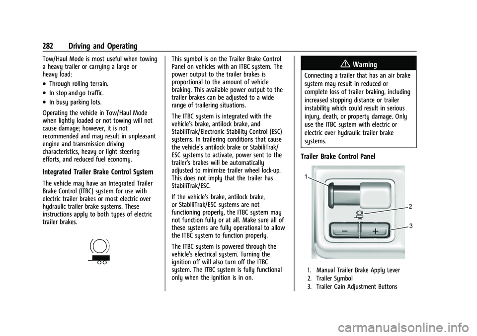
Trailer Brake Control Panel
1. Manual Trailer Brake Apply Lever
2. Trailer Symbol
3. Trailer Gain Adjustment Buttons
Page 284 of 433
Chevrolet Silverado 2500 HD/3500 HD Owner Manual (GMNA-Localizing-U.
S./Canada/Mexico-14632154) - 2021 - CRC - 11/20/20
Driving and Operating 283
The trailer symbol on the control panel will
light amber when a trailer with electric
brakes is connected.
The ITBC control panel is on the center
stack. SeeInstrument Panel Overview 04.
The control panel allows adjustment to the
amount of output, referred to as Trailer
Gain, available to the trailer brakes and
allows manual application of the trailer
brakes. Use the ITBC control panel and the
DIC trailer brake display page to adjust and
display power output to the trailer brakes.
Trailer Brake DIC Display Page
The ITBC display page indicates:
.Trailer Gain setting
.Output to the trailer brakes
.Trailer connection
.System operational status
To display:
.Scroll through the DIC menu pages
.Press a Trailer Gain (+) or (−) button
.Activate the Manual Trailer Brake Apply
Lever
TRAILER GAIN: Press a Trailer Gain button to
recall the current Trailer Gain setting. Each
press and release of the gain buttons will
then change the Trailer Gain setting. Press the Trailer Gain (+) or (-) to adjust. Press and
hold to continuously adjust the Trailer Gain.
To turn the output to the trailer off, adjust
the Trailer Gain setting to 0.0. This setting
can be adjusted from 0.0 to 10.0 with a
trailer connected or disconnected.
TRAILER OUTPUT: This displays anytime a
trailer with electric brakes is connected.
Output to the trailer brakes is based on the
amount of vehicle braking present and
relative to the Trailer Gain setting. Output is
displayed from 0 to 100% for each gain
setting.
The Trailer Output will indicate
“- - - - - -”on
the Trailer Brake Display Page whenever the
following occur:
.No trailer is connected.
.A trailer without electric brakes is
connected. No DIC message displays.
.A trailer with electric brakes has become
disconnected. A CHECK TRAILER WIRING
message displays on the DIC.
.There is a fault present in the wiring to
the trailer brakes. A CHECK TRAILER
WIRING message displays on the DIC.
.The ITBC system is not working due to a
fault. A SERVICE TRAILER BRAKE SYSTEM
message displays in the DIC.
Manual Trailer Brake Apply Lever
Slide this lever right to apply the trailer’s
electric brakes independent of the vehicle’s
brakes. Use this lever to adjust the Trailer
Gain to achieve proper power output to the
trailer brakes. Under certain circumstances,
this lever can also be used to apply
additional trailer braking. The trailer and
vehicle brake lamps will come on when
either the vehicle brakes or trailer brakes are
applied and properly connected.
Trailer Gain Adjustment Procedure
Trailer Gain should be set for a specific
trailering condition and it must be
readjusted anytime vehicle loading, trailer
loading, or road surface conditions change.
{Warning
Trailer brakes that are over-gained or
under-gained may not stop the vehicle
and the trailer as intended and can result
in a crash. Always follow the instructions
to set the Trailer Gain for the proper
trailer stopping performance.
To adjust Trailer Gain for each towing
condition:
Page 285 of 433
Chevrolet Silverado 2500 HD/3500 HD Owner Manual (GMNA-Localizing-U.
S./Canada/Mexico-14632154) - 2021 - CRC - 11/20/20
284 Driving and Operating
1. Drive the vehicle with the trailerattached on a level road surface
representative of the towing condition
and free of traffic at about 32–40 km/h
(20–25 mph) and fully apply the Manual
Trailer Brake Apply Lever.
Adjusting Trailer Gain at speeds lower
than 32–40 km/h (20–25 mph) may
result in an incorrect gain setting.
2. Adjust the Trailer Gain, using the Trailer Gain (+) or (−) adjustment buttons, to
just below the point of trailer wheel
lock-up, indicated by trailer wheel squeal
or tire smoke when a trailer wheel locks.
Trailer wheel lock-up may not occur if
towing a heavily loaded trailer. Adjust
the Trailer Gain to the highest allowable
setting for the towing condition.
3. Readjust Trailer Gain anytime vehicle loading, trailer loading, or road surface
conditions change or if trailer wheel
lock-up is noticed at any time while
towing.
Other ITBC-Related DIC Messages
TRAILER CONNECTED: This message will
briefly display when a trailer with electric
brakes is first connected to the vehicle. This
message will automatically turn off in about 10 seconds. This message can be
acknowledged before it automatically
turns off.
CHECK TRAILER WIRING: This message will
display if:
.The ITBC system first determines
connection to a trailer with electric brakes
and then the trailer harness becomes
disconnected from the vehicle.
If the disconnect occurs while the vehicle
is stationary, this message will
automatically turn off in about
30 seconds. This message will also turn
off if it is acknowledged or if the trailer
harness is reconnected.
If the disconnect occurs while the vehicle
is moving, this message will continue
until the ignition is turned off. This
message will also turn off if it is
acknowledged or if the trailer harness is
reconnected.
.There is an electrical fault in the wiring to
the trailer brakes. This message will
continue as long as there is an electrical
fault in the trailer wiring. This message
will also turn off if it is acknowledged.
To determine whether the electrical fault is
on the vehicle side or trailer side of the
trailer wiring harness connection:
1. Disconnect the trailer wiring harness from the vehicle.
2. Turn the ignition off.
3. Wait 10 seconds, then turn the ignition back to RUN.
4. If the CHECK TRAILER WIRING message reappears, the electrical fault is on the
vehicle side.
If the CHECK TRAILER WIRING message only
reappears when connecting the trailer wiring
harness to the vehicle, the electrical fault is
on the trailer side.
SERVICE TRAILER BRAKE SYSTEM: This
message will display when there is a
problem with the ITBC system. If this
message continues over multiple ignition
cycles, have the vehicle serviced.
If either the CHECK TRAILER WIRING or
SERVICE TRAILER BRAKE SYSTEM message
displays while driving, the ITBC system may
not be fully functional or may not function
at all. When traffic conditions allow,
carefully pull the vehicle over to the side of
the road and turn the ignition off. Check the
wiring connection to the trailer and turn the
Page 318 of 433

Chevrolet Silverado 2500 HD/3500 HD Owner Manual (GMNA-Localizing-U.
S./Canada/Mexico-14632154) - 2021 - CRC - 11/20/20
Vehicle Care 317
Brake pads should always be replaced as
complete axle sets.
How to Reset the Brake Pad Life System
The system will automatically detect when
significantly worn brake pads are replaced.
When the ignition is turned on after new
pads and wear sensors are installed, a
message will display. Follow the prompts to
reset the system.
The brake pad life system can also be
manually reset:1. Display Brake Pad Life on the DIC. See Driver Information Center (DIC) (Base
Level) 0119 or
Driver Information Center (DIC) (Midlevel
and Uplevel) 0120.
2. Press the thumbwheel or the trip odometer reset stem if the vehicle does
not have DIC buttons. Select front or rear
pads as appropriate.
3. Select YES on the confirmation message, or press the trip odometer reset stem on
a base level DIC. Repeat for pads on the
other axle if they were also replaced.
How to Disable the Brake Pad Life
System
The brake pad life system can be turned off.
This may be necessary if aftermarket brake
pads without wear sensors are installed.
When the system is turned off, the front
and rear brake pad life percentages will not
display. However, the built-in wear
indicators that make a high-pitched warning
sound when the brake pads are worn can
still determine when the pads should be
replaced. See Brakes0316.
To turn off the brake pad life system: 1. Display Brake Pad Life on the DIC. See Driver Information Center (DIC) (Base
Level) 0119 or
Driver Information Center (DIC) (Midlevel
and Uplevel) 0120.
2. Select DISABLE.
To turn the brake pad life system back on,
follow the above steps but select ENABLE in
Step 2.
Brake Fluid
The brake master cylinder reservoir is filled
with GM approved DOT 3 brake fluid as
indicated on the reservoir cap. See Engine
Compartment Overview 0304 for the
location of the reservoir.
Checking Brake Fluid
With the vehicle in P (Park) on a level
surface, the brake fluid level should be
between the minimum and maximum marks
on the brake fluid reservoir.
There are only two reasons why the brake
fluid level in the reservoir may go down:
.Normal brake lining wear. When new
linings are installed, the fluid level goes
back up.
.A fluid leak in the brake hydraulic system.
Have the brake hydraulic system fixed.
With a leak, the brakes will not
work well.