2021 AUDI A6 Luggage
[x] Cancel search: LuggagePage 92 of 332

Storage and convenience
Roof rack
General information
Applies to: vehicles with roof rack mount
5
aI
a
=|
Applies to: sedan
Fig. 81 Roof: mounting points
Applies to: Avant/allroad
Fig. 82 Roof rail: mounting points on the Avant Q), allroad
®
If luggage or cargo is to be carried on the roof,
you must observe the following:
— These roof racks are the basis for a complete
roof rack system. Only roof racks that are suita-
ble for your vehicle may be used. Audi recom-
mends roof racks and attachments from the
Audi Genuine Accessories program.
— Make sure the roof rack is mounted on the vehi-
cle only at the specified locations @ or @) or
©.
90
— Note the permitted axle load, permitted total
weight, and permitted roof load of your vehicle
= page 314. The roof load is the total of the
weight of the roof rack, the attachments and
the cargo you are carrying. However, you must
also note the permitted load of the carrier sys-
tem being used.
A\ WARNING
— Follow the installation instructions provided
with the roof rack system. If you do not se-
cure the roof rack system and objects on the
roof correctly, they could come loose from
the vehicle and cause an accident.
— The risk of an accident increases when using
a roof rack system, because it changes the
driving characteristics by shifting the center
of gravity and/or the increasing the surface
area exposed to wind. You may need to
adapt your driving style and speed to the
current conditions.
® Note
Make sure that the luggage compartment lid
and the panoramic glass roof* do not come in-
to contact with objects on the roof when they
are open.
@) For the sake of the environment
Energy usage will increase because of the in-
creased wind resistance. Remove the roof rack
when you are no longer using it.
Page 121 of 332

4K0012721BE
Trailer towing
Trailer towing
Driving with a trailer
eT e e eeu)
Your vehicle is primarily intended for transport-
ing people and luggage. However, if you drive
with a trailer, follow the technical requirements,
the operation and driving tips, and the legal reg-
ulations.
Driving with a trailer affects the vehicle's energy
usage, performance, and wear. It also requires
higher concentration from the driver.
Z\ WARNING
Do not transport any people in a trailer due to
the risk of fatal injury.
Technical requirements
Trailer hitch
Only use a trailer hitch with a removable ball
hitch mount and ball hitch. The trailer hitch must
be permitted for the vehicle, the trailer and the
permitted total weight of the trailer being
pulled. Above all, it must be securely and safely
attached to the vehicle trailer.
Never mount a trailer hitch on the bumper. The
trailer hitch must be mounted in a way that does
not impair the function of the bumper. Do not
make any changes to the exhaust system and the
brake system.
Check regularly if the trailer hitch is securely
mounted. Always follow the instructions given by
the trailer hitch manufacturer.
Trailer brakes
If the trailer has its own brake system, then fol-
low the manufacturer specifications. However,
the brake system on the trailer must never be
connected to the vehicle brake system.
Engine cooling system
Driving with a trailer means a higher load on the
engine and the cooling system. The cooling sys-
tem must be designed for additional load and
contain enough coolant > @®.
CG) Note
Longer inclines cannot be driven without a
suitable cooling system, especially if the out-
side temperatures are high. Otherwise, this
increases the risk of engine damage.
Operating instructions
Towing capacity
Your vehicle can only be operated with class 1 or
class 2 trailers.
Load distribution
Poor cargo load and distribution can negatively
impact vehicle handling. Load the trailer based
on the following criteria as much as possible:
— Store objects in the vehicle luggage compart-
ment, if possible. The vehicle should always
carry the heaviest possible load and the trailer
should have the lightest possible load.
— Distribute the load in the trailer so that the
heavy objects are as close to the axle as possi-
ble.
— Secure objects so that they do not slide.
— Utilize the maximum permitted tongue weight
if possible.
Tires
Set the tire pressure on your vehicle for a “full
load”; see the tire pressure sticker > page 266. If
necessary, also adjust the tire pressure on the
trailer according to the manufacturer's specifica-
tions.
The trailer and the vehicle should be equipped
with winter tires when driving in winter tempera-
tures.
Outside mirrors
If you cannot see the traffic behind the trailer
with the standard exterior mirrors, then you
must attach additional exterior mirrors. Adjust
them so you have a sufficient visibility behind
you.
Exterior lighting
Follow the legal regulations for lighting on your
trailer that are applicable in the country where
119
>
Page 127 of 332

4K0012721BE
Assist systems
Rear area
Depending on the vehicle equipment, the follow-
ing sensors and cameras may be installed:
— Rearview camera in the luggage compartment
lid
— Radar sensors at the rear corners of the vehicle
— Rear and side ultrasonic sensors
Switching the systems
on and off
ZA\ WARNING
Applies to: vehicles with laser scanner
— The surface of the laser scanner can become
hot during operation, which increases the
risk of burns.
— The laser scanner contains a class 1 laser in
accordance with IEC 60825-1:2014. When
used according to regulations, the laser is
not dangerous. Opening the laser module
and removing covers is not permitted. Doing
so could cause permanent injuries to the
eyes.
— Any repair work on the laser module must
be performed by an authorized Audi dealer
or authorized Audi Service Facility; other-
wise the vehicle's operating license may be
voided. Incorrect repairs may cause limited
functionality and eye damage.
@) Tips
Applies to: vehicles with laser scanner
— The possible emissions are below the
threshold for class 1 lasers.
— Complies with 21 CFR 1040.10 and
1040.11 except for deviations pursuant to
Laser Notice No. 50, dated June 24, 2007.
@ Tips
— The locations of the sensors may differ
slightly depending on vehicle equipment.
— Some sensors are installed under vehicle
components and cannot be seen from the
outside.
— The system complies with United States FCC
regulations and ISED regulations
=> page 311.
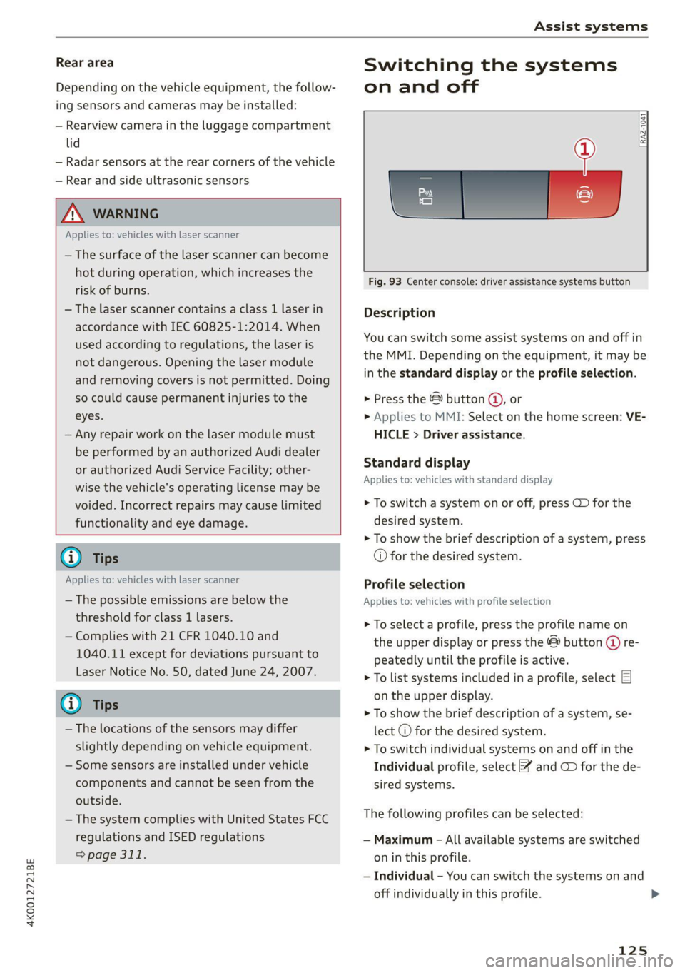
Fig. 93 Center console: driver assistance systems button
Description
You can switch some assist systems on and off in
the MMI. Depending on the equipment, it may be
in the standard display or the profile selection.
> Press the © button @, or
> Applies to MMI: Select on the home screen: VE-
HICLE > Driver assistance.
Standard display
Applies to: vehicles with standard display
> To switch a system on or off, press CD for the
desired system.
> To show the brief description of a system, press
© for the desired system.
Profile selection
Applies to: vehicles with profile selection
> To select a profile, press the profile name on
the upper display or press the & button (@ re-
peatedly until the profile is active.
> To list systems included in a profile, select E]
on the upper display.
> To show the brief description of a system, se-
lect @ for the desired system.
> To switch individual systems on and off in the
Individual profile, select ¥ and CD for the de-
sired systems.
The following profiles can be selected:
— Maximum - All available systems are switched
on in this profile.
— Individual - You can switch the systems on and
off individually in this profile.
125
Page 166 of 332

Parking and maneuvering
Applies to: vehicles with rearview camera/peripheral cameras
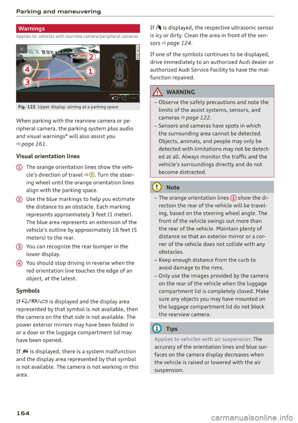
Fig. 122 Upper display: aiming at a parking space
When parking with the rearview camera or pe-
ripheral camera, the parking system plus audio
and visual warnings* will also assist you
=> page 161.
Visual orientation lines
@ The orange orientation lines show the vehi-
cle's direction of travel >@. Turn the steer-
ing wheel until the orange orientation lines
align with the parking space.
@) Use the blue markings to help you estimate
the distance to an obstacle. Each marking
represents approximately 3 feet (1 meter).
The blue area represents an extension of the
vehicle's outline by approximately 16 feet (5
meters) to the rear.
@® You can recognize the rear bumper in the
lower display.
@ You should stop driving in reverse when the
red orientation line touches the edge of an
object, at the latest.
Symbols
If 2/&9/< is displayed and the display area
represented by that symbol is not available, then
the camera on the that side is not available. The
power exterior mirrors may have been folded in
or a door or the luggage compartment lid may
have been opened.
If # is displayed, there is a system malfunction
and the display area represented by that symbol
is not available. The camera is not working in this
area.
164
If Avis displayed, the respective ultrasonic sensor
is icy or dirty. Clean the area in front of the sen-
sors > page 124.
If one of the symbols continues to be displayed,
drive immediately to an authorized Audi dealer or
authorized Audi Service Facility to have the mal-
function repaired.
ZA WARNING
— Observe the safety precautions and note the
limits of the assist systems, sensors, and
cameras > page 122.
— Sensors and cameras have spots in which
the surrounding area cannot be detected.
Objects, animals, and people may only be
detected with limitations may not be detect-
ed at all. Always monitor the traffic and the
vehicle's surroundings directly and do not
become distracted.
() Note
— The orange orientation lines @ show the di-
rection the rear of the vehicle will be travel-
ing, based on the steering wheel angle. The
front of the vehicle swings out more than
the rear of the vehicle. Maintain plenty of
distance so that an exterior mirror or a cor-
ner of the vehicle does not collide with any
obstacles.
— Keep enough distance from the curb to
avoid damage to the rims.
— Only use the images provided by the camera
on the rear of the vehicle when the luggage
compartment lid is completely closed. Make
sure any objects you may have mounted on
the luggage compartment lid do not block
the rearview camera.
G) Tips
Applies to vehicles with air suspension: The
accuracy of the orientation lines and blue sur-
faces on the camera display decreases when
the vehicle is raised or lowered with the air
suspension.
Page 168 of 332

Parking and maneuvering
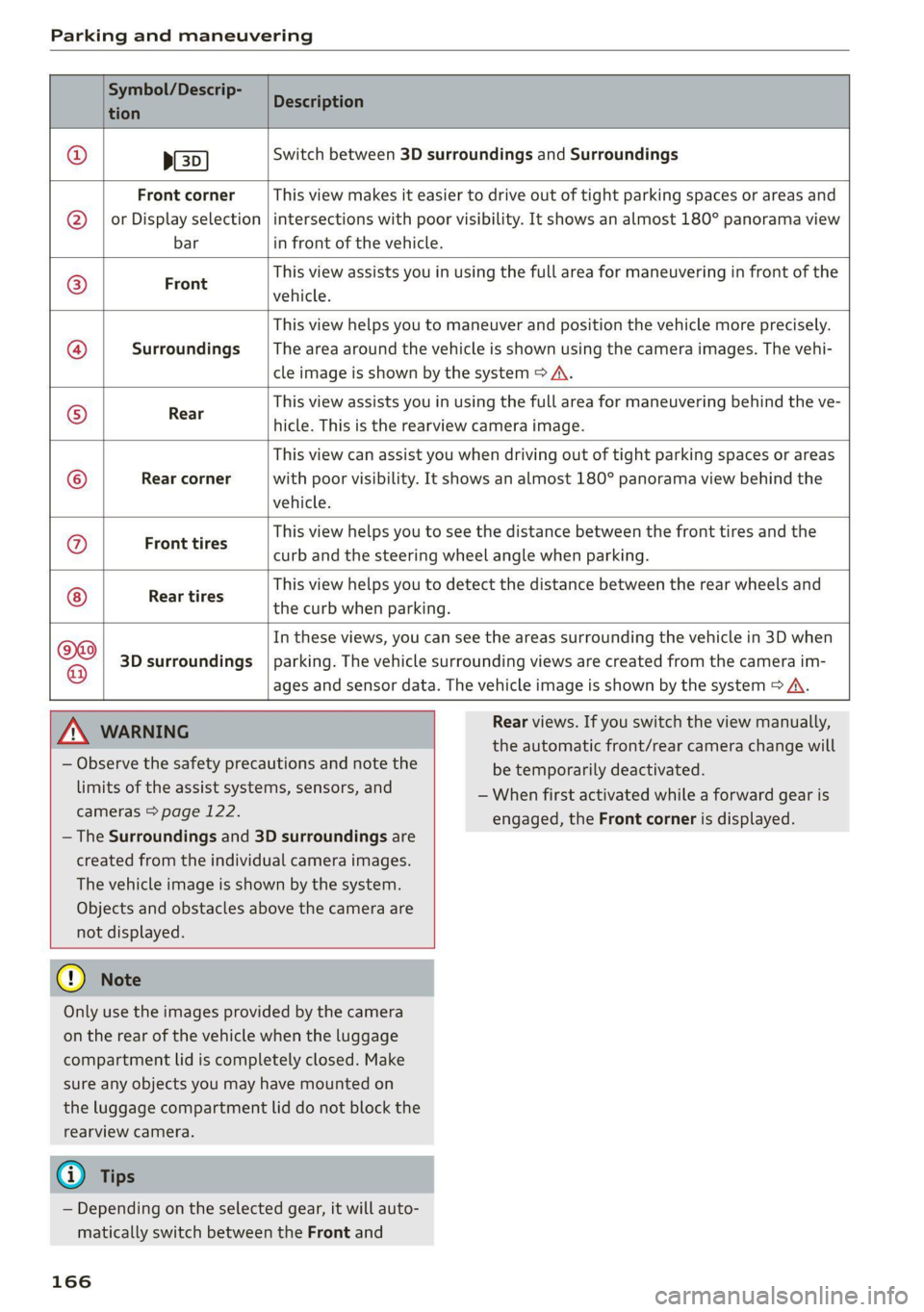
Symbol/Descrip-
tion
Description
psp
Switch between 3D surroundings and Surroundings
Front corner
or Display selection
bar
This view makes it easier to drive out of tight parking spaces or areas and
intersections with poor visibility. It shows an almost 180° panorama view
in front of the vehicle.
Front
This view assists you in using the full area for maneuvering in front of the
vehicle.
Surroundings
This view helps you to maneuver and position the vehicle more precisely.
The area around the vehicle is shown using the camera images. The vehi-
cle image is shown by the system > A\.
Rear
This view assists you in using the full area for maneuvering behind the ve-
hicle. This is the rearview camera image.
Rear corner
This view can assist you when driving out of tight parking spaces or areas
with poor visibility. It shows an almost 180° panorama view behind the
vehicle.
Front tires
This view helps you to see the distance between the front tires and the
curb and the steering wheel angle when parking.
Rear tires
This view helps you to detect the distance between the rear wheels and
the curb when parking.
3D surroundings
In these views, you can see the areas surrounding the vehicle in 3D when
parking. The vehicle surrounding views are created from the camera im-
©f$;/@/e|
®
|o/e
|e]
e@
|e
ages and sensor data. The vehicle image is shown by the system > A\.
ZA\ WARNING
— Observe the safety precautions and note the
limits of the assist systems, sensors, and
cameras > page 122.
— The Surroundings and 3D surroundings are
created from the individual camera images.
The vehicle image is shown by the system.
Objects and obstacles above the camera are
not displayed.
@) Note
Only use the images provided by the camera
on the rear of the vehicle when the luggage
compartment lid is completely closed. Make
sure any objects you may have mounted on
the luggage compartment lid do not block the
rearview camera.
@) Tips
— Depending on the selected gear, it will auto-
matically switch between the Front and
166
Rear views. If you switch the view manually,
the automatic front/rear camera change will
be temporarily deactivated.
— When first activated while a forward gear is
engaged, the Front corner is displayed.
Page 179 of 332

4K0012721BE
Parking and maneuvering
Preparing the vehicle
> To enable the selected parking space (2) for re-
mote controlled parking, press E @ on the up-
per display.
> If you have already approached a parking space
in the vehicle, remote controlled parking can be
activated to continue with the rest of the park-
ing process. To enable remote controlled park-
ing, press [J in the upper display.
> Exit the vehicle while the engine is running and
take the vehicle key with you. Always keep both
the vehicle key and the mobile device with you
during the entire remote controlled parking
process.
> Make sure that all doors and the luggage com-
partment lid are closed.
Starting the parking process
> Start the myAudi app soon, or the function will
be canceled.
> Pay attention to the path of the vehicle. If the
traffic situation permits, park your vehicle in
the parking space using the mobile device
> JX. The vehicle key and the mobile device
cannot be more than approximately 20 feet
(6 m) away from the vehicle.
> Pay attention to the path of the vehicle. In un-
clear situations, pause the parking process us-
ing
the mobile device. For example, this may be
necessary if an obstacle appears or the vehicle
comes very close to an obstacle.
> To resume the parking process, start it again on
the mobile device. The rest of the parking proc-
ess will be recalculated based on the vehicle po-
sition.
End of the parking process
If an obstacle appears, stop the parking process
=> page 178.
The parking process will end automatically once
the vehicle has reached the end point in the park-
ing space. Once parking is successfully complet-
ed, the parking lock will be engaged, the parking
brake will be set, and the engine will switch off.
The vehicle will also be locked.
ZA WARNING
— Observe the safety precautions and note the
limits of the assist systems, sensors, and
cameras > page 122.
— Failing to pay careful attention to the vehi-
cle's surroundings increases the risk of an
accident. Park your vehicle with the mobile
device only if you are sure that no obstacle is
in the vehicle's path or under the vehicle,
and that no obstacles will move into the ve-
hicle's path.
@ Tips
— If the parking space is located in a garage, it
must be detected correctly by the vehicle.
When the parking space is detected com-
pletely, the edges of the space will be high-
lighted @).
— The parking process can only be started if
the vehicle key is located outside the vehicle
after the vehicle is prepared. Always keep
both the vehicle key and the mobile device
with you during the entire remote control-
led parking process.
— Remote controlled parking may be restrict-
ed or unavailable in situations such as the
following:
—If the ESC is restricted or switched off, or
if there is a malfunction.
—If there is another vehicle key inside the
vehicle or nearby.
— The system can incorrectly interpret parking
space barriers (such as parking curbs). Take
over the parking process = page 178 if the
vehicle is not completely inside the parking
space or if the vehicle tries to drive over the
parking space barrier.
177
Page 243 of 332

4K0012721BE
Checking and Filling
@ Tips
The fuel filler door on your vehicle does not
lock if you lock the vehicle from the inside us-
ing
the central locking switch.
Fuel filler door emergency release
Applies to: vehicles with manual fuel filler door release
If the central locking system malfunctions, the
fuel filler door can be unlocked manually.
Fig. 156 Version @)/ version @) Right cover in the luggage
compartment: removing the cover
Fig. 157 Luggage compartment: fuel filler door emergency
release
The emergency opening mechanism is located
behind the right cover in the luggage compart-
ment.
> Remove the screwdriver from the vehicle tool
kit > page 286.
> Insert the flat side of the screwdriver carefully
into the slot between the side trim panel and
the cover > fig. 156 (arrows) and pry out the
cover. Keep in mind that a power cable for the
socket is located on the rear side.
> To unlock the fuel filler door, loosen the red
loop from the retainer and then pull on the
loop carefully > fig. 1579@©.
> Press on the left side of the fuel filler door to
open it > page 2339, fig. 154.
® Note
Only pull on the loop until you feel resistance.
You
will not hear it release. If you continue to
pull, you could damage the emergency re-
lease mechanism.
Emissions control
system
General information
ZA WARNING
The temperature of the exhaust system is
high, both when driving and after stopping
the engine.
— Never touch the exhaust tail pipes once they
have become hot. This could result in burns.
— Do not park your vehicle over flammable
materials such as grass or leaves because
the high temperature of the emissions sys-
tem could start a fire.
— Do not apply underbody protectant in the
exhaust system area, because this increases
the risk of fire.
Catalytic converter
Observe the safety precautions > page 241, Gen-
eral information.
The vehicle may only be driven with unleaded
gasoline, or the catalytic converter will be de-
stroyed.
Never drive until the tank is completely empty.
The irregular supply of fuel that results from that >
241
Page 272 of 332

Wheels
passengers that the vehicle is in-
tended to carry (“seating capaci-
ty”) with an assumed weight of
150 lbs. (68 kg) for each passen-
ger at a designated seating posi-
tion and the total weight of any
luggage in the vehicle. If you tow
a trailer, the weight of the trailer
hitch and the tongue weight of
the loaded trailer must be includ-
ed as part of the vehicle load.
The Gross Axle Weight Rating
(“GAWR”) is the maximum load
that can be applied at each of the
vehicle’s two axles.
The fact that there is an upper
limit to your vehicle’s Gross Vehi-
cle Weight Rating means that the
total weight of whatever is being
carried in the vehicle (including
the weight of a trailer hitch and
the tongue weight of the loaded
trailer) is limited. The more pas-
sengers in the vehicle or passen-
gers who are heavier than the
standard weights assumed mean
that less weight can be carried as
luggage.
The Gross Vehicle Weight Rating
and the Gross Axle Weight Rating
are listed on the safety compli-
270
ance sticker label located on the
driver’s side B-pillar.
Z\ WARNING
Overloading a vehicle can cause
loss of vehicle control, a crash
or other accident, serious per-
sonal injury, and even death.
—Carrying more weight than
your vehicle was designed to
carry will prevent the vehicle
from handling properly and in-
crease the risk of the loss of
vehicle control.
—The brakes on a vehicle that
has been overloaded may not
be able to stop the vehicle
within a safe distance.
—Tires ona vehicle that has
been overloaded can fail sud-
denly, including a blowout and
sudden deflation, causing loss
of control and a crash.
—Always make sure that the to-
tal load being transported -
including the weight of a trail-
er hitch and the tongue
weight of a loaded trailer -
does not make the vehicle
heavier than the vehicle’s
Gross Vehicle Weight Rating.