2021 ALFA ROMEO STELVIO instrument panel
[x] Cancel search: instrument panelPage 50 of 280
GETTING TO KNOW YOUR VEHICLE
48
If the windshield washer is used with the rain
sensor activated, the normal washing cycle is
performed, and then the rain sensor resumes
its normal automatic operation.
NOTE:
Keep the glass in the sensor area clean.
Deactivation
To turn off the Rain Sensing Wipers, use the
wiper switch or place the ignition in the OFF
position.
In the event of malfunction of the rain sensor
while it is active, the windshield wiper oper-
ates intermittently at a speed consistent with
the sensitivity setting of the rain sensor,
whether or not there is rain on the glass for as
long as the sensor failure is indicated on the
display.
The sensor continues to operate and it is
possible to set the windshield wiper to contin -
uous mode (1 or 2). The failure indication
remains on for as long as the sensor is active. The rain sensor is able to recognize and auto
-
matically adjust itself in the presence of the
following conditions:
Presence of dirt on the controlled surface
(e.g. salt, dirt, etc.).
Presence of streaks of water caused by the
worn window wiper blades.
Difference between day and night.
Rear Window Wiper/Washer
Push the windshield wiper lever downward to
activate/deactivate continuous rear wiper
operation.
Push the windshield wiper lever towards the
instrument panel to activate the rear window
washer (a brief push activates one washing
cycle, keeping the stalk pushed washes
continuously until the stalk is released).
Shifting the vehicle into REVERSE with the
windshield wiper operating activates a single
cycle of the rear window wiper.
Headlamp Washers — If Equipped
The windshield wiper lever operates the head -
light washers when the ignition is in the ON
position and the headlights are turned on. To
use the headlight washers, pull the lever
toward you and release it. The headlight
washers will spray a timed high-pressure spray
of washer fluid onto each headlight lens. In
addition, the windshield washers will spray the
windshield and the windshield wipers will
cycle.
NOTE:
The headlight washers work on every tenth
wash cycle request.
CLIMATE CONTROLS
The Climate Control system allows you to regu -
late the temperature, air flow, and direction of
air circulating throughout the vehicle. The
controls are located on the touchscreen and
on the instrument panel below the radio.
21_GU_OM_EN_USC_t.book Page 48
Page 55 of 280
53
NOTE:
The MAX-DEF function remains active for
approximately three minutes once the engine
coolant reaches the proper temperature.
When the function is on, AUTO mode will deac-
tivate. The only manual operations possible
are adjusting blower speed and turning off the
Rear Window Defrost.
Pushing the button switches off the
MAX-DEF function.
Air Temperature Adjustment
Rotate the driver or passenger Temperature
Adjustment Knob clockwise for warmer
temperatures or counterclockwise for cooler
temperatures. The set temperatures are
shown on the radio system.
Push the SYNC button to sync the driver and
passenger air temperatures.
Rotate the passenger Temperature Adjust -
ment Knob to cancel the SYNC function. This
will set a new passenger side temperature.
Rotate the Temperature Adjustment Knob fully
clockwise to engage the HI (maximum heating)
setting or fully counterclockwise to engage the
LO (maximum cooling) setting. To deactivate
these functions, rotate the Temperature
Adjustment Knob to the desired temperature.
Rear passengers’ temperature is linked to
driver side selection.
AUTO Button
When the AUTO button is pushed (indicator
illuminated), the Climate Control system auto -
matically adjusts the following settings:
Quantity and distribution of air flow in the
passenger compartment
The air conditioner
Air recirculation
Cancels any manual settings
Selecting the AUTO function illuminates the
indicator on the A/C button.
If air distribution or the fan speed is manually
adjusted, the AUTO button indicator will turn
off to indicate that the Climate Control system
is no longer in AUTO mode.
After a manual adjustment, push the AUTO
button to resume the automatic system.
SYNC Button
Push the SYNC button (indicator illuminated)
to sync the passenger side air temperature
with the driver side air temperature.
This function makes temperature regulation
easier when the driver is traveling alone.
Turn the passenger Temperature Adjustment
Knob or push the passenger side Air Distribu-
tion Selection Button to change the passenger
side air temperature and return to separate air
temperature management.
Blower Speed
Turn the Blower Speed Knob to increase or
decrease the blower speed. The speed is
displayed with lighted indicators in the radio
system display.
Maximum fan speed = all indicators illumi -
nated on the radio system display
Minimum fan speed = one indicator illumi -
nated on the radio system display
The fan can be turned off by rotating the
Blower Speed Knob counterclockwise to the
off position (all segments on the radio system
display are turned off).
NOTE:
To restore automatic control of the fan speed,
push the AUTO button.
Air Distribution Selection
Push the Air Distribution Selection button on
the faceplate to change the mode of air distri -
bution.
NOTE:
In AUTO mode, the Climate Controls automati -
cally manage the air distribution. When set
manually, the respective symbols on the radio
system indicate the air distribution setting.
Panel Mode
Air comes from the outlets in the
instrument panel to ventilate the
chest and face. Each of these outlets
can be individually adjusted to direct
21_GU_OM_EN_USC_t.book Page 53
Page 56 of 280
GETTING TO KNOW YOUR VEHICLE
54
the flow of air. The air vanes of the center
outlets and outboard outlets can be moved up
and down or side to side to regulate airflow
direction. There is a shut off wheel located
below the air vanes to shut off or adjust the
amount of airflow from these outlets.
Bi-Level Mode
Air comes from the instrument panel
outlets and floor outlets. A slight
amount of air is directed through the
defrost and side window demister
outlets.
NOTE:
Bi-Level mode is designed under comfort
conditions to provide cooler air out of the
panel outlets and warmer air from the floor
outlets.
Floor Mode
Air comes from the floor outlets. A
slight amount of air is directed
through the defrost and side window
demister outlets. This setting heats
the passenger compartment the quickest.
Mix Mode
Air is directed through the floor,
defrost, and side window demister
outlets. This setting works best in
cold or snowy conditions that require
extra heat to the windshield. This setting is
good for maintaining comfort while reducing
moisture on the windshield.
Front Defrost And Panel Mode
Air flow is distributed between the
windshield demisting/defrosting
vents and side/central dashboard
vents. This setting allows air to flow
to the windshield on sunny days.
Front Defrost And Bi-Level Mode
Air flow is distributed to all vents.
Switching The Climate Control System On/
Off
To Turn Off The Climate Control System
Rotate the Air Speed Adjustment Knob
completely counterclockwise to turn off the
Climate Control system.
With the air conditioner is off:
Air recirculation is on
The A/C compressor is off
The fan is off
The heated rear window can be activated/
deactivated
NOTE:
The Climate Control system stores the previ -
ously set temperatures and resumes opera -
tion when any button on the system is pushed. To Turn On The Climate Control System
To switch the Climate Control system on in
automatic mode, push the AUTO button.
Operating Mode
The Climate Control system can be activated
in different ways. It is recommended to use the
automatic function. Push the AUTO button and
set the desired temperatures.
The automatic system adjusts the tempera
-
ture, quantity, and distribution of air intro -
duced into the passenger compartment. It
also controls air recirculation and the activa -
tion of the air conditioner.
At any time during automatic operation, you
can change the temperature, activate or deac -
tivate the Rear Defrost, activate SYNC, acti -
vate or deactivate the air conditioner, and
activate or deactivate air recirculation. The
system will automatically adjust to the new
settings.
Climate Control Display Settings
The Climate Control settings are visible on the
radio screen.
The display on the radio system is a pop up
window, which is activated by pushing the
buttons or turning the knobs on the Climate
Control system. The indicator lights located on
the buttons and knobs indicate that the
selected feature is on/off. If no operation is
performed for a predetermined time, the
pop-up will close on the display.
21_GU_OM_EN_USC_t.book Page 54
Page 57 of 280
55
Humidity Sensor
The Humidity Sensor helps prevent the
windows from fogging up. The AUTO function
(indicator illuminated) must be on for the
Humidity Sensor to function.
When outside temperature is low, the system
may turn the compressor on and turn air recir-
culation off for safer driving.
Stop/Start
The Stop/Start system shuts off the engine
when the vehicle speed is 0 mph (0 km/h), as
a fuel conservation measure.
In order to maintain comfort in the cabin, the
Stop/Start feature will not activate if any of the
following conditions exist:
The Climate Control system is in AUTO mode
(indicator illuminated), and the vehicle has
yet to reach the set temperature
The Climate Control system is in LO
maximum cooling
The Climate Control system is in HI
maximum heating
The Climate Control system is in the
MAX-DEF status
When the Stop/Start system is active, the
engine will restart if the inside temperature
changes significantly, or if the LO setting, or
MAX-DEF setting, is activated. With Stop/Start system on (engine is OFF), air
flow is reduced to keep the compartment
comfort conditions for longer.
Until the temperature drastically changes
within the cabin, the climate control system
will continue to maintain the temperature
while the engine is off. By deactivating the
Stop/Start system with the button (located
by the headlight switch), the climate control
system operates normally according to the
settings.
NOTE:
In harsh climate conditions, limit the use of
the Stop/Start system to prevent the
compressor from continuously switching on
and off. This will cause rapid misting of the
windows and the accumulation of humidity
in the passenger compartment.
When the Stop/Start system is on, the
climate control system will always take air in
from outside, reducing the probability of the
windows fogging up.
System Maintenance
In winter months, the Climate Control system
must be turned on at least once a month for
approximately 10 minutes.
Have the system inspected at an authorized
dealer before the summer.
INTERIOR STORAGE AND
EQUIPMENT
Glove Compartment
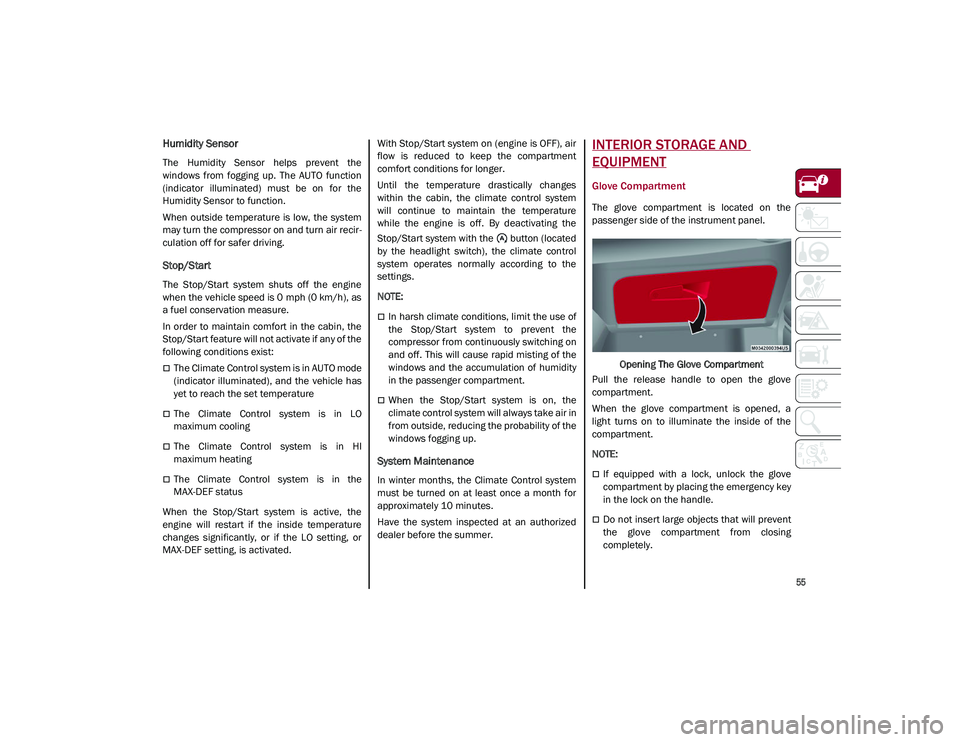
The glove compartment is located on the
passenger side of the instrument panel.
Opening The Glove Compartment
Pull the release handle to open the glove
compartment.
When the glove compartment is opened, a
light turns on to illuminate the inside of the
compartment.
NOTE:
If equipped with a lock, unlock the glove
compartment by placing the emergency key
in the lock on the handle.
Do not insert large objects that will prevent
the glove compartment from closing
completely.
21_GU_OM_EN_USC_t.book Page 55
Page 58 of 280
GETTING TO KNOW YOUR VEHICLE
56
Center Console
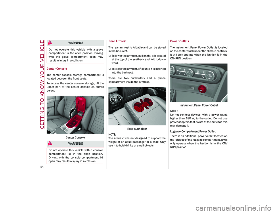
The center console storage compartment is
located between the front seats.
To access the center console storage, lift the
upper part of the center console as shown
below.Center Console
Rear Armrest
The rear armrest is foldable and can be stored
in the backrest.
To lower the armrest, pull on the tab located
at the top of the seatback and fold it down -
ward.
To close the armrest, lift it until it is inserted
into the backrest.
There are two cupholders and a phone
compartment inside the armrest.
Rear Cupholder
NOTE:
The armrest was not designed to support the
weight of an adult passenger or a child. Only
use it to hold drinks or small objects.
Power Outlets
The Instrument Panel Power Outlet is located
on the center stack under the climate controls.
It will only operate when the ignition is in the
ON/RUN position.
Instrument Panel Power Outlet
NOTE:
Do not connect devices, with a power rating
higher than 180 W, to the outlet. Do not use
power adapters that do not fit the outlet as this
may damage it.
Luggage Compartment Power Outlet
There is an additional power outlet located on
the left side of the luggage compartment. It will
only operate when the ignition is in the ON/
RUN position.
WARNING!
Do not operate this vehicle with a glove
compartment in the open position. Driving
with the glove compartment open may
result in injury in a collision.
WARNING!
Do not operate this vehicle with a console
compartment lid in the open position.
Driving with the console compartment lid
open may result in injury in a collision.
21_GU_OM_EN_USC_t.book Page 56
Page 63 of 280
61
Proceed as follows:
1. With the ignition in the ON/RUN position,make sure the sunroof glass is fully closed
(sunshade open).
2. Open the driver’s side door, and place the ignition in the OFF position.
3. Within five seconds, place the ignition in the ACC or ON/RUN position.
4. Within 10 seconds, push and hold the sunroof close switch (forward). After 8 -
10 seconds of holding the switch, the
re-initialization process will begin.
Continue to hold the switch while the
sunroof motor cycles, and the sunshade
will fully close.
5. Once the sunroof glass and the power sunshade have stopped motion, release
the sunroof close switch, then push and
hold it again within five seconds. Continue
to hold the switch while the sunshade fully
opens, the sunroof glass fully opens,
followed by the glass fully closing then the
sunshade fully closing.
6. Release the switch once all of the opera -
tions stop. Re-initialization of the sunroof
motors is now complete.
NOTE:
If the switch is released prior to full completion
of the operations described, the entire
re-initialization procedure must be repeated
from step 1. 7. Confirm express operations for the
sunroof glass and sunshade are functional
for opening and closing operations.
Sunroof Maintenance
Use only a non-abrasive cleaner and a soft
cloth to clean the glass panel. Periodically
check for and clear out any debris that may
have collected in the tracks.
HOOD
Opening The Hood
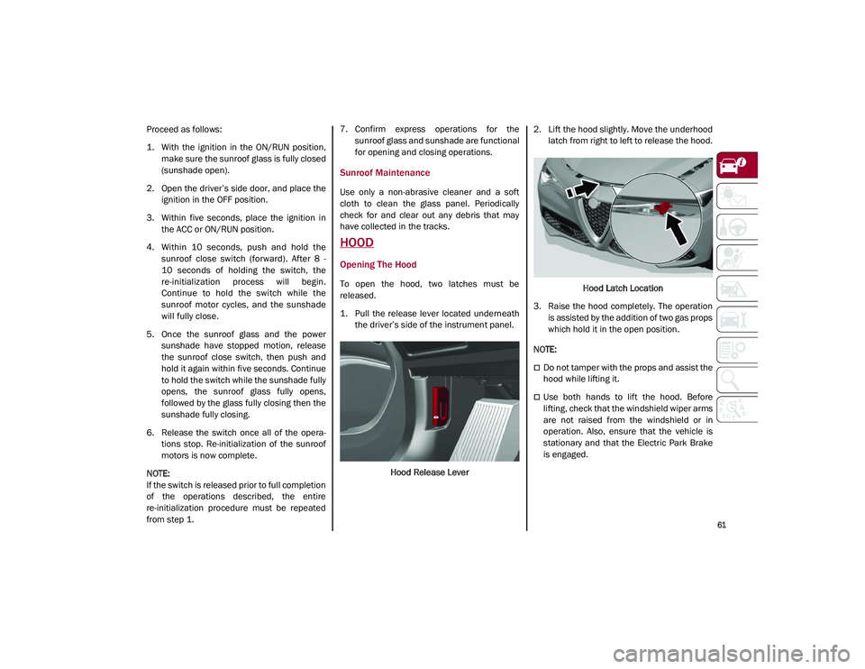
To open the hood, two latches must be
released.
1. Pull the release lever located underneaththe driver’s side of the instrument panel.
Hood Release Lever 2. Lift the hood slightly. Move the underhood
latch from right to left to release the hood.
Hood Latch Location
3. Raise the hood completely. The operation is assisted by the addition of two gas props
which hold it in the open position.
NOTE:
Do not tamper with the props and assist the
hood while lifting it.
Use both hands to lift the hood. Before
lifting, check that the windshield wiper arms
are not raised from the windshield or in
operation. Also, ensure that the vehicle is
stationary and that the Electric Park Brake
is engaged.
21_GU_OM_EN_USC_t.book Page 61
Page 69 of 280
67
GETTING TO KNOW YOUR INSTRUMENT PANEL
This section gives you all the information you need to understand and use the instrument panel correctly.
INSTRUMENT PANEL FEATURES
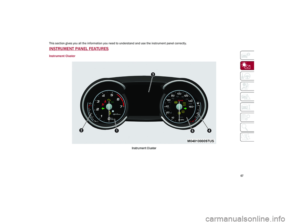
Instrument Cluster
Instrument Cluster
21_GU_OM_EN_USC_t.book Page 67
Page 70 of 280
GETTING TO KNOW YOUR INSTRUMENT PANEL
68
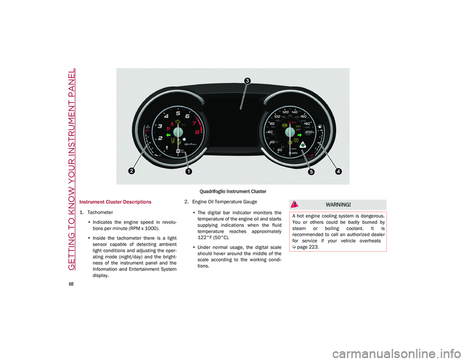
Quadrifoglio Instrument Cluster
Instrument Cluster Descriptions
1. Tachometer•Indicates the engine speed in revolu-
tions per minute (RPM x 1000).
• Inside the tachometer there is a light
sensor capable of detecting ambient
light conditions and adjusting the oper-
ating mode (night/day) and the bright-
ness of the instrument panel and the
Information and Entertainment System display. 2. Engine Oil Temperature Gauge
•The digital bar indicator monitors the
temperature of the engine oil and starts
supplying indic ations when the fluid
temperature reaches approximately
122°F (
50°C).
• Under normal usage, the digital scale
should hover around the middle of the
scale according to the working condi-
tions.
WARNING!
A hot engine cooling system is dangerous.
You or others could be badly burned by
steam or boiling coolant. It is
recommended to call an authorized dealer
for service if your vehicle overheats
Ú
page 223.
21_GU_OM_EN_USC_t.book Page 68