2021 ALFA ROMEO GIULIA seats
[x] Cancel search: seatsPage 35 of 284

33
Power Lumbar
The power lumbar switch is located on the
outboard side of the power seat. Push the
switch forward or rearward to increase or
decrease the lumbar support. Push the switch
upward or downward to raise or lower the
lumbar support.
Seat Cushion Extension — If Equipped
Lift the adjustment lever and push the front of
the cushion forward or rearward to extend the
cushion by a few inches (centimeters).Seat Cushion Extension
Power Bolster Adjustment — If Equipped
Push the power bolster adjustment buttons to
regulate the width of the backrest through the
lateral padding.
Seatback Width Adjustment
Easy Entry Function
The Easy Entry function is designed to move
the driver side seat forward automatically by
2.36 inches (60 mm) to make it easier for the
driver to get in and out of the car.
The movement is activated only if the seat is
set to a driving position which is in front of the
B-Pillar of the vehicle. The function is associated with power driver
seats for each of the three stored positions.
The Easy Entry function can be activated/
deactivated through the radio system. Refer to
the Information and Entertainment System
Owner’s Manual Supplement for further infor
-
mation.
Heated Seats — If Equipped
For information on use with the Remote Start
system, see
Ú
page 21.
6 — Adjustment Lever
4 — Power Adjustable Bolster Buttons
5 — Driver Memory Settings Buttons
WARNING!
Persons who are unable to feel pain to the
skin because of advanced age, chronic
illness, diabetes, spinal cord injury, medi
-
cation, alcohol use, exhaustion or other
physical condition must exercise care
when using the seat heater. It may cause
burns even at low temperatures, espe -
cially if used for long periods of time.
Do not place anything on the seat or seat -
back that insulates against heat, such as
a blanket or cushion. This may cause the
seat heater to overheat. Sitting in a seat
that has been overheated could cause
serious burns due to the increased
surface temperature of the seat.
21_GA_OM_EN_USC_t.book Page 33
Page 36 of 284

GETTING TO KNOW YOUR VEHICLE
34
Front Heated Seats — If Equipped
NOTE:
Quadrifoglio vehicles equipped with Sparco
Racing Seats will not be equipped with the
heated seat feature.
A push of the heated seat buttons located on
the instrument panel, near the climate
controls, will select the heat levels in order of
highest to lowest. A fourth push of the button
will turn the heated seat off.
NOTE:
The heated seat function can also be activated
through the radio system. Refer to the Infor-
mation and Entertainment System Owner’s
Manual Supplement for further information.
You can select three heating levels:
Maximum — three LED indicators illumi -
nated on the buttons
Average — two LED indicators illuminated
on the buttons
Minimum — one LED indicator illuminated
on the buttons Heated Seat Buttons
NOTE:
After selecting a heating level, heat will be
felt within a few minutes.
The engine must be running for the heated
seats to operate.
The “minimum” setting is automatically
deactivated once a certain period of time
has elapsed.
Rear Heated Seats — If Equipped
If equipped with rear heated seats, the
controls can be found on the rear of the center
console and will function the same as the front
heated seat controls.
Rear Heated Seat Buttons
NOTE:
To preserve the battery charge, this function
cannot be activated when the engine is off.
21_GA_OM_EN_USC_t.book Page 34
Page 37 of 284

35
Head Restraints
Head restraints are designed to reduce the
risk of injury by restricting head movement in
the event of a rear impact. Head restraints
should be adjusted so that the top of the head
restraint is located above the top of your ear.
Sparco Racing Seat Head Restraints
(Quadrifoglio Vehicles) — If Equipped
Head restraints on Sparco Racing Seats (front
seats) are non-adjustable and non-removable.
The non-adjustable head restraints consist of a
trimmed foam covering over the upper structure
of the seatbacks and are intended to help
protect you and the passenger from neck injury.
Adjust the seatbacks to their upright, on-road
positions so that the head restraint is posi-
tioned as close as possible to the back of your
head.
Front Head Restraints
The front head restraints may be
height-adjustable. To raise the head restraint, pull up on the head
restraint until it clicks into place.
To lower the head restraint, push in the adjust
-
ment button and lower the head restraint to
the desired height while holding the button.
Then, release the adjustment button.
NOTE:
To allow maximum visibility for the driver, if the
head restraints are not in use, lower the head
restraint all the way.
Rear Head Restraint Adjustment
The height of the outboard head restraints can
be adjusted. The head restraint of the center
seat can only be removed. The height cannot
be adjusted.
WARNING!
A loose head restraint thrown forward in a
collision or hard stop could cause serious
injury or death to occupants of the vehicle.
Always securely stow removed head
restraints in a location outside the occu -
pant compartment.
ALL the head restraints MUST be rein -
stalled in the vehicle to properly protect
the occupants. Follow the re-installation
instructions above prior to operating the
vehicle or occupying a seat.
Do not place items over the top of the
Reactive Head Restraint, such as coats,
seat covers or portable DVD players.
These items may interfere with the opera -
tion of the Reactive Head Restraint in the
event of a collision and could result in
serious injury or death.
WARNING!
All occupants, including the driver, should
not operate a vehicle or sit in a vehicle’s
seat until the head restraints are placed in
their proper positions in order to minimize
the risk of neck injury in the event of a
crash.
Head restraints should never be adjusted
while the vehicle is in motion. Driving a
vehicle with the head restraints improp -
erly adjusted or removed could cause
serious injury or death in the event of a
collision.
WARNING!
All occupants, including the driver, should
not operate a vehicle or sit in a vehicle’s
seat until the head restraints are placed in
their proper positions in order to minimize
the risk of neck injury in the event of a
crash.
Head restraints should never be adjusted
while the vehicle is in motion. Driving a
vehicle with the head restraints improp -
erly adjusted or removed could cause
serious injury or death in the event of a
collision.
21_GA_OM_EN_USC_t.book Page 35
Page 48 of 284

GETTING TO KNOW YOUR VEHICLE
46
Rear Overhead Light
The rear overhead lights are activated or deac-
tivated by two on/off switches located within
the lights on the ceiling above the rear seats.
Rear Overhead Light
The light turns on when a door is opened.
NOTE:
The light will turn off automatically after a few
minutes if a door is left open. To turn it on
again, open another door or close and reopen
the same door.
Instrument Panel Dimmer Control
With the daytime running lights or headlights
on, rotate the dimmer control upward to
increase the instrument panel brightness and
the control button icons. Rotate the dimmer
control downward to decrease brightness.
Dimmer Control
WINDSHIELD WIPERS AND
WASHERS
The windshield wiper/washer lever is located
on the right side of the steering wheel.
The windshield wipers will only operate with
the ignition in the ACC or ON/RUN position.
1 — Passenger Rear Overhead Light
2 — Driver Rear Overhead Light
3 — Driver Rear Overhead Light Switch
4 — Passenger Rear Overhead Light Switch
CAUTION!
Turn the windshield wipers off when
driving through an automatic car wash.
Damage to the windshield wipers may
result if the wiper control is left in any posi -
tion other than off.
In cold weather, always turn off the wiper
switch and allow the wipers to return to
the “Park” position before turning off the
engine. If the wiper switch is left on and
the wipers freeze to the windshield,
damage to the wiper motor may occur
when the vehicle is restarted.
Always remove any buildup of snow that
prevents the windshield wiper blades from
returning to the off position. If the wind -
shield wiper control is turned off and the
blades cannot return to the off position,
damage to the wiper motor may occur.
21_GA_OM_EN_USC_t.book Page 46
Page 58 of 284
GETTING TO KNOW YOUR VEHICLE
56
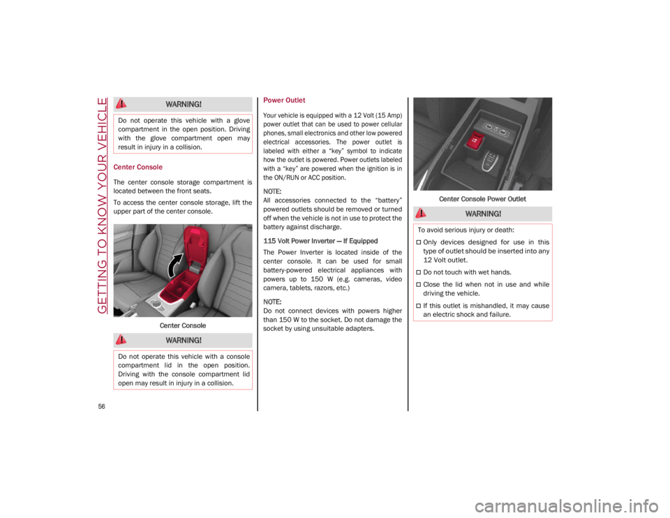
Center Console
The center console storage compartment is
located between the front seats.
To access the center console storage, lift the
upper part of the center console.Center Console
Power Outlet
Your vehicle is equipped with a 12 Volt (15 Amp)
power outlet that can be used to power cellular
phones, small electronics and other low powered
electrical accessories. The power outlet is
labeled with either a “key” symbol to indicate
how the outlet is powered. Power outlets labeled
with a “key” are powered when the ignition is in
the ON/RUN or ACC position.
NOTE:
All accessories connected to the “battery”
powered outlets should be removed or turned
off when the vehicle is not in use to protect the
battery against discharge.
115 Volt Power Inverter — If Equipped
The Power Inverter is located inside of the
center console. It can be used for small
battery-powered electrical appliances with
powers up to 150 W (e.g. cameras, video
camera, tablets, razors, etc.)
NOTE:
Do not connect devices with powers higher
than 150 W to the socket. Do not damage the
socket by using unsuitable adapters. Center Console Power Outlet
WARNING!
Do not operate this vehicle with a glove
compartment in the open position. Driving
with the glove compartment open may
result in injury in a collision.
WARNING!
Do not operate this vehicle with a console
compartment lid in the open position.
Driving with the console compartment lid
open may result in injury in a collision.
WARNING!
To avoid serious injury or death:
Only devices designed for use in this
type of outlet should be inserted into any
12 Volt outlet.
Do not touch with wet hands.
Close the lid when not in use and while
driving the vehicle.
If this outlet is mishandled, it may cause
an electric shock and failure.
21_GA_OM_EN_USC_t.book Page 56
Page 88 of 284

86
(Continued)
STARTING AND OPERATING
STARTING THE ENGINE
Before starting the engine, be sure to adjust
the seat, the interior rear view mirror, and the
door mirrors, and fasten the seat belt
correctly.
Never press the accelerator pedal before
starting the engine.
If necessary, messages indicating the starting
procedure will be shown in the display.
Starting Procedure
Proceed as follows:
1. Apply the Electric Park Brake and set thegear selector to PARK (P) or NEUTRAL (N).
2. Fully press the brake pedal without touching the accelerator.
3. Briefly push the ignition button.
4. If the engine doesn't start within a few seconds, you need to repeat the proce -
dure.
If the problem persists, contact an authorized
dealer.
Remote Starting System
This system uses the key fob to start the
engine conveniently from outside the vehicle
while still maintaining security. The system
has a range of at least 300 feet (91 meters).
The remote starting system also activates the
climate control, the heated seats (if
equipped), and the heated steering wheel (if
equipped), depending on temperatures
outside and inside of the vehicle.
NOTE:
Obstructions between the vehicle and key fob
may reduce this range.
WARNING!
When leaving the vehicle, always remove
the key fob from the vehicle and lock your
vehicle.
Never leave children alone in a vehicle, or
with access to an unlocked vehicle.
Allowing children to be in a vehicle unat -
tended is dangerous for a number of
reasons. A child or others could be seriously
or fatally injured. Children should be warned
not to touch the parking brake, brake pedal
or the transmission gear selector.
Do not leave the key fob in or near the
vehicle, or in a location accessible to chil -
dren. A child could operate power windows,
other controls, or move the vehicle.
Do not leave children or animals inside
parked vehicles in hot weather. Interior
heat build-up may cause serious injury or
death.
WARNING!
Never pour fuel or other flammable liquid
into the throttle body air inlet opening in
an attempt to start the vehicle. This could
result in flash fire causing serious
personal injury.
Do not attempt to push or tow your vehicle
to get it started. Vehicles equipped with an
automatic transmission cannot be started
this way. Unburned fuel could enter the
catalytic converter and once the engine
has started, ignite and damage the
converter and vehicle.
If the vehicle has a discharged battery,
booster cables may be used to obtain a start
from a booster battery or the battery in
another vehicle
Ú
page 199. This type of
start can be dangerous if done improperly.
CAUTION!
To prevent damage to the starter, do not
continuously crank the engine for more
than 25 seconds at a time. Wait 60
seconds before trying again.
WARNING! (Continued)
21_GA_OM_EN_USC_t.book Page 86
Page 155 of 284

153
NOTE:
If the safety belts of the front seats are not
correctly fastened, the system will not inter-
vene on the braking system (only audible and
visual signals will be provided).
Changing The System Sensitivity
The sensitivity of the system can be changed
through the radio system menu, choosing from
one of the following three options: "Near",
"Medium" or "Far". Refer to the description in
the Information and Entertainment System
Owner’s Manual Supplement for how to
change the settings.
The default setting is "Medium". With this
setting, the system warns the driver of a
possible collision with the vehicle in front
when that vehicle is at a standard distance,
between that of the other two settings.
With the system sensitivity set to "Far", the
system will warn the driver of a possible colli -
sion with the vehicle in front when that vehicle
is at a greater distance, thus providing the
possibility of acting on the brakes more lightly
and gradually. This setting provides the driver
with the maximum possible reaction time to
prevent a potential collision.
With the option set to "Near", the system will
alert the driver of a possible collision with the
vehicle in front when that vehicle is close. This
setting offers the driver a lower reaction time
compared to the "Medium" and "Far" settings,
in the event of a potential collision, but
permits more dynamic driving of the vehicle. The system sensitivity setting is kept in the
memory when the engine is turned off.
System Limited Operation Warning
If a dedicated message is displayed, a condi
-
tion limiting the system operation may have
occurred. The possible reasons of this limita -
tion are if something is blocking the camera
view, or a fault is present.
If an obstruction is signaled, clean the area of
the windshield.
Although the vehicle can still be driven in
normal conditions, the system may be not
completely available.
When the conditions limiting the system func -
tions end, this will go back to normal and
complete operation. Should the fault persist,
contact an authorized dealer.
System Failure Signaling
If the system turns off and a dedicated
message is shown on the display, it means
that there is a fault with the system.
In this case, it is still possible to drive the
vehicle, but you are advised to contact an
authorized dealer as soon as possible.
Radar Indication Not Available
If conditions are such that the radar cannot
detect obstacles correctly, the system is deac -
tivated and a dedicated message appears on
the display. This generally occurs in the event
of poor visibility, such as when it is snowing or
raining heavily. The function of this system can also be tempo
-
rarily reduced due to obstructions such as
mud, dirt or ice on the fascia/bumper. In such
cases, a dedicated message will be shown on
the display and the system will be deactivated.
This message can sometimes appear in condi -
tions of high reflectivity (e.g. tunnels with
reflective tiles or ice or snow). When the condi -
tions limiting the system functions end, it will
go back to normal and complete operation.
In certain cases, this dedicated message
could be displayed when the radar is not
detecting any vehicles or objects within its
view range.
If atmospheric conditions are not the reason
behind this message, check if the sensor is
dirty. It could be necessary to clean or remove
any obstructions in the area.
If the message appears frequently, even in the
absence of atmospheric conditions such as
snow, rain, mud or other obstructions, contact an
authorized dealer for a sensor alignment check.
In the absence of visible obstructions, manu -
ally removing the decorative cover trim and
cleaning the radar surface could be required.
Have this operation performed at an autho -
rized dealer.
NOTE:
It is recommended that you do not install
devices, accessories, or aerodynamic attach -
ments in front of the sensor or darken it in any
way, as this can compromise the correct func -
tioning of the system.
21_GA_OM_EN_USC_t.book Page 153
Page 161 of 284
159
OCCUPANT RESTRAINT
SYSTEMS
Some of the most important safety features in
your vehicle are the restraint systems:
Occupant Restraint Systems Features
Seat Belt Systems
Supplemental Restraint Systems (SRS) Air
Bags
Child Restraints
Some of the safety features described in this
section may be standard equipment on some
models, or may be optional equipment on others.
If you are not sure, ask an authorized dealer.
Important Safety Precautions
Please pay close attention to the information
in this section. It tells you how to use your
restraint system properly, to keep you and
your passengers as safe as possible.
Here are some simple steps you can take to mini -
mize the risk of harm from a deploying air bag:
1. Children 12 years old and under should always ride buckled up in the rear seat of
a vehicle with a rear seat.
2. A child who is not big enough to wear the vehicle seat belt properly must be secured
in the appropriate child restraint or
belt-positioning booster seat in a rear
seating position
Ú
page 174. 3. If a child from 2 to 12 years old (not in a
rear-facing child restraint) must ride in the
front passenger seat, move the seat as far
back as possible and use the proper child
restraint
Ú
page 174.
4. Never allow children to slide the shoulder belt behind them or under their arm.
5. You should read the instructions provided with your child restraint to make sure that
you are using it properly.
6. All occupants should always wear their lap and shoulder belts properly.
7. The driver and front passenger seats should be moved back as far as practical
to allow the front air bags room to inflate.
8. Do not lean against the door or window. If your vehicle has side air bags, and deploy -
ment occurs, the side air bags will inflate
forcefully into the space between occu -
pants and the door and occupants could
be injured.
9. If the air bag system in this vehicle needs to be modified to accommodate a disabled
person, see
Ú
page 270 for customer
service contact information.
Seat Belt Systems
Buckle up even though you are an excellent
driver, even on short trips. Someone on the
road may be a poor driver and could cause a
collision that includes you. This can happen far
away from home or on your own street.
Research has shown that seat belts save lives,
and they can reduce the seriousness of inju -
ries in a collision. Some of the worst injuries
happen when people are thrown from the
vehicle. Seat belts reduce the possibility of
ejection and the risk of injury caused by
striking the inside of the vehicle. Everyone in a
motor vehicle should be belted at all times.
WARNING!
Never place a rear-facing child restraint in
front of an air bag. A deploying passenger
front air bag can cause death or serious
injury to a child 12 years or younger,
including a child in a rear-facing child
restraint.
Never install a rear-facing child restraint in
the front seat of a vehicle. Only use a
rear-facing child restraint in the rear seat.
If the vehicle does not have a rear seat, do
not transport a rear-facing child restraint
in that vehicle.
21_GA_OM_EN_USC_t.book Page 159