2020 YAMAHA TRICITY 300 Front wheel
[x] Cancel search: Front wheelPage 8 of 114

Table of contentsSafety information ............................ 1-1
Further safe-riding points ............... 1-5
Description ....................................... 2-1
Left view ......................................... 2-1
Right view ....................................... 2-2
Controls and instruments ............... 2-3
Smart key system ........................... 3-1
Smart key system ........................... 3-1
Operating range of the smart key system......................................... 3-2
Handling of the smart key and mechanical keys ......................... 3-3
Smart key ....................................... 3-4
Replacing the smart key battery..... 3-6
Main switch .................................... 3-7
Stan din g assist ................................. 4-1
Standing assist ............................... 4-1
Instrument an d control functions ... 5-1
Indicator lights and warning
lights............................................ 5-1
Multi-function meter unit ................ 5-3
Handlebar switches ........................ 5-8
Front brake lever .......................... 5-10
Brake pedal .................................. 5-10
Rear brake lever ........................... 5-11
Parking brake lever ....................... 5-12
ABS .............................................. 5-12 Traction control system ................ 5-13
Fuel tank cap ................................ 5-15
Fuel ............................................... 5-16
Fuel tank overflow hose ................ 5-18
Catalytic converter ........................ 5-18
Storage compartment ................... 5-18
Adjusting the shock absorber
assemblies ................................. 5-20
Auxiliary DC jack ........................... 5-20
Sidestand ...................................... 5-21
Ignition circuit cut-off system ....... 5-22
For your safety – pre-operation
checks ............................................... 6-1
Operation an d important ri din g
points ................................................. 7-1
Engine break-in ............................... 7-1
Starting the engine .......................... 7-2
Starting off ...................................... 7-3
Acceleration and deceleration ........ 7-3
Braking ............................................ 7-3
Tips for reducing fuel consumption ................................ 7-4
Parking ............................................ 7-4
Perio dic maintenance an d
a d justment ........................................ 8-1
Tool kit ............................................ 8-2
Periodic maintenance charts .......... 8-3 Periodic maintenance chart for the
emission control system ............. 8-3
General maintenance and lubrication chart .......................... 8-4
Removing and installing the
panel............................................ 8-9
Checking the spark plug............... 8-10
Canister ........................................ 8-11
Engine oil and oil filter element..... 8-12
Why Yamalube.............................. 8-14
Final transmission oil .................... 8-14
Coolant ......................................... 8-15
Air filter and V-belt case air filter elements .................................... 8-17
Checking the throttle grip free play ............................................ 8-21
Valve clearance............................. 8-21
Tires .............................................. 8-22
Cast wheels .................................. 8-23
Checking the front brake lever
free play..................................... 8-24
Checking the rear brake lever free play..................................... 8-24
Checking the parking brake ......... 8-25
Checking the front and rear brake pads ................................ 8-25
Checking the brake fluid level ...... 8-26
Changing the brake fluid .............. 8-27
Checking the V-belt ...................... 8-27
Checking and lubricating the cables ........................................ 8-28UBX9E0E0.book Page 1 Monday, January 20, 2020 10:54 AM
Page 9 of 114
Table of contents
Checking and lubricating the
throttle grip and cable ................8-28
Lubricating the front and rear brake levers................................8-28
Checking and lubricating the
brake pedal ................................8-29
Checking and lubricating the centerstand and sidestand ........8-29
Checking the front fork..................8-30
Checking the steering ...................8-31
Lubricating the steering bearings .....................................8-31
Checking the wheel bearings ........8-31
Battery ...........................................8-32
Replacing the fuses .......................8-33
Vehicle lights .................................8-35
Replacing a turn signal light bulb ............................................8-35
Replacing the license plate light bulb ............................................8-36
Troubleshooting ............................8-36
Troubleshooting chart ...................8-38
Emergency mode .........................8-40
Vehicle care an d stora ge .................9-1
Matte color caution .........................9-1
Care .................................................9-1
Storage ............................................9-3 Specifications
................................. 10-1
Consumer information ................... 11-1
Identification numbers .................. 11-1
Diagnostic connector.................... 11-2
Vehicle data recording .................. 11-2
In dex ................................................ 12-1
UBX9E0E0.book Page 2 Monday, January 20, 2020 10:54 AM
Page 14 of 114
Safety information
1-5
1appropriate. Refer to page 8-22 for tire
specifications and more information on
replacing your tires.
Transportin
g the Vehicle
Be sure to observe the following in-
structions before transporting the vehi-
cle in another vehicle. Remove all loose items from the
vehicle.
Point the front wheels straight
ahead on the trailer or in the truck
bed, and choke it in a rail to pre-
vent movement.
Secure the vehicle with tie-downs
or suitable straps that are at-
tached to solid parts of the vehi-
cle, such as the frame or upper
front fork triple clamp (and not, for
example, to rubber-mounted han-
dlebars or turn signals, or parts
that could break). Choose the lo-
cation for the straps carefully so
the straps will not rub against
painted surfaces during transport.
The suspension should be com-
pressed somewhat by the tie-
downs, if possible, so that the ve-
hicle will not bounce excessively
during transport.
EAU60590
Further safe-ri din g points Be sure to signal clearly when
making turns.
Braking can be extremely difficult
on a wet road. Avoid hard braking,
because the vehicle could slide.
Apply the brakes slowly when
stopping on a wet surface.
Slow down as you approach a
corner or turn. Once you have
completed a turn, accelerate
slowly.
Be careful when passing parked
cars. A driver might not see you
and open a door in your path.
Railroad crossings, streetcar rails,
iron plates on road construction
sites, and manhole covers be-
come extremely slippery when
wet. Slow down and cross them
with caution. Keep the vehicle up-
right, otherwise it could slide out
from under you.
The brake pads or linings could
get wet when you wash the vehi-
cle. After washing the vehicle,
check the brakes before riding.
UBX9E0E0.book Page 5 Monday, January 20, 2020 10:54 AM
Page 43 of 114
Instrument and control functions
5-12
5
EAU89340
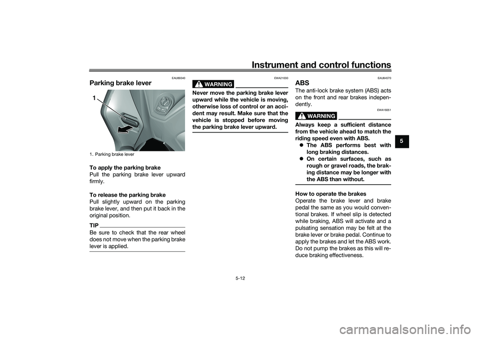
Parkin g b rake leverTo apply the parkin g b rake
Pull the parking brake lever upward
firmly.
To release the parkin g b rake
Pull slightly upward on the parking
brake lever, and then put it back in the
original position.TIPBe sure to check that the rear wheel
does not move when the parking brake
lever is applied.
WARNING
EWA21030
Never move the parkin g b rake lever
upwar d while the vehicle is movin g,
otherwise loss of control or an acci-
d ent may result. Make sure that the
vehicle is stopped before movin g
the parkin g b rake lever upwar d.
EAU84570
ABSThe anti-lock brake system (ABS) acts
on the front and rear brakes indepen-
dently.
WARNING
EWA16051
Always keep a sufficient d istance
from the vehicle ahea d to match the
ri din g speed even with ABS.
The ABS performs b est with
lon g b rakin g d istances.
On certain surfaces, such as
rou gh or g ravel roa ds, the b rak-
in g d istance may be lon ger with
the ABS than without.How to operate the brakes
Operate the brake lever and brake
pedal the same as you would conven-
tional brakes. If wheel slip is detected
while braking, ABS will activate and a
pulsating sensation may be felt at the
brake lever or brake pedal. Continue to
apply the brakes and let the ABS work.
Do not pump the brakes as this will re-
duce braking effectiveness.
1. Parking brake lever1
UBX9E0E0.book Page 12 Monday, January 20, 2020 10:54 AM
Page 44 of 114

Instrument and control functions
5-13
5
The ABS performs a self-check
when you first start off. During this
time a clicking noise from the hy-
draulic unit may be audible, and if
the brake lever or brake pedal is
applied a vibration can be felt, but
this is not a malfunction.
The brake system will revert to a
conventional brake system in case
of ABS malfunction.
NOTICE
ECA20100
Be careful not to damag e the wheel
sensor or wheel sensor rotor; other-
wise, improper performance of the
ABS will result.
EAU89320
Traction control systemThe traction control system (TCS)
helps maintain traction when acceler-
ating on slippery surfaces, such as un-
paved or wet roads. If sensors detect
that the rear wheel is starting to slip
(uncontrolled spinning), the traction
control system assists by regulating
engine power until traction is restored.
When traction control has engaged,
the “ ” indicator light will flash. You
may notice changes in engine re-
sponse or exhaust sound.
WARNING
EWA18860
The traction control system is not a
su bstitute for rid ing appropriately
for the con ditions. Traction control
cannot prevent loss of traction due
to excessive speed when entering
turns, when acceleratin g har d at a
sharp lean an gle, or while brakin g,
an d cannot prevent front wheel slip-
pin g. As with any vehicle, approach
surfaces that may be slippery with
caution an d avoi d especially slip-
pery surfaces.
1. Front wheel sensor rotor
2. Front wheel sensor
1
2
1. Rear wheel sensor
2. Rear wheel sensor rotor
1 2
2 2
UBX9E0E0.book Page 13 Monday, January 20, 2020 10:54 AM
Page 65 of 114
Periodic maintenance an d a djustment
8-5
8
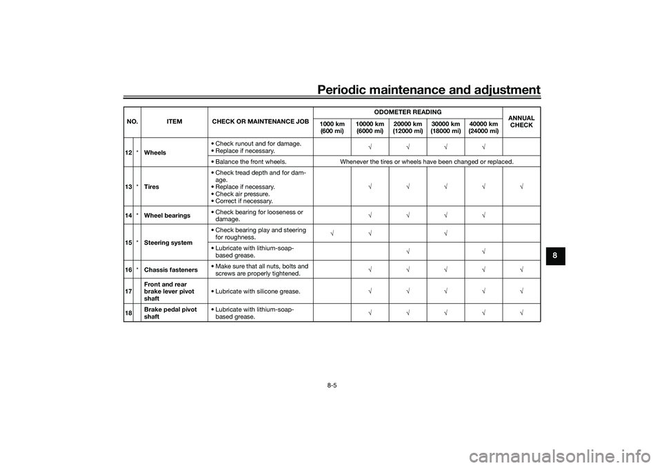
12 *Wheels • Check runout and for damage.
• Replace if necessary.
√√√√
• Balance the front wheels. Whenever the tires or wheels have been changed or replaced.
13 *Tires • Check tread depth and for dam-
age.
• Replace if necessary.
• Check air pressure.
• Correct if necessary. √√√√√
14 *Wheel bearin gs • Check bearing for looseness or
damage. √√√√
15 *Steerin g system • Check bearing play and steering
for roughness. √√ √
• Lubricate with lithium-soap- based grease. √√
16 *Chassis fasteners • Make sure that all nuts, bolts and
screws are properly tightened. √√√√√
17 Front an
d rear
b rake lever pivot
shaft • Lubricate with silicone grease.
√√√√√
18 Brake ped
al pivot
shaft • Lubricate with lithium-soap-
based grease. √√√√√
NO. ITEM CHECK OR MAINTENANCE JOB
ODOMETER READING
ANNUAL
CHECK
1000 km
(600 mi) 10000 km
(6000 mi) 20000 km
(12000 mi) 30000 km
(18000 mi) 40000 km
(24000 mi)
UBX9E0E0.book Page 5 Monday, January 20, 2020 10:54 AM
Page 83 of 114

Periodic maintenance an d a djustment
8-23
8
WARNING
EWA10472
Have a Yamaha d ealer replace
excessively worn tires. Besid es
b ein g ille gal, operatin g the vehi-
cle with excessively worn tires
d ecreases ri din g sta bility an d
can lead to loss of control.
The replacement of all wheel
and b rake-relate d parts, inclu d-
in g the tires, shoul d b e left to a
Yamaha dealer, who has the
necessary professional knowl-
e dge an d experience to do so.
Ride at mo derate spee ds after
chan gin g a tire since the tire
surface must first be “ broken
in” for it to develop its optimal
characteristics.Tire information
This model is equipped with tubeless
tires and rubber tire air valves.
Tires age, even if they have not been
used or have only been used occasion-
ally. Cracking of the tread and sidewall
rubber, sometimes accompanied by
carcass deformation, is an evidence of ageing. Old and aged tires shall be
checked by tire specialists to ascertain
their suitability for further use.
WARNING
EWA10462
The front an
d rear tires shoul d b e of
the same make an d d esi gn, other-
wise the han dlin g characteristics of
the vehicle may be different, which
coul d lea d to an acci dent.After extensive tests, only the tires list-
ed below have been approved for this
model by Yamaha.
EAU61160
Cast wheelsTo maximize the performance, durabil-
ity, and safe operation of your vehicle,
note the following points regarding the
specified wheels.
The wheel rims should be
checked for cracks, bends, warp-
age or other damage before each
ride. If any damage is found, have
a Yamaha dealer replace the
wheel. Do not attempt even the
smallest repair to the wheel. A de-
formed or cracked wheel must be
replaced.
The front wheels should be bal-
anced whenever either the tires or
wheels have been changed or re-
placed. An unbalanced wheel can
result in poor performance, ad-
verse handling characteristics,
and a shortened tire life.
Front tire:
Size:120/70-14M/C 55P
Manufacturer/model: BRIDGESTONE/BATTLAX SCF
Rear tire:
Size:140/70-14M/C 62P
Manufacturer/model:
BRIDGESTONE/BATTLAX SCR
UBX9E0E0.book Page 23 Monday, January 20, 2020 10:54 AM
Page 85 of 114
Periodic maintenance an d a djustment
8-25
8
EAU89061
Checkin g the parkin g b rakeThe parking brake must be checked
and adjusted at the intervals specified
in the periodic maintenance and lubri-
cation chart, or sooner if the parking
brake does not properly hold the
wheel.
EAU22393
Checkin g the front an d rear
b rake pa dsThe front and rear brake pads must be
checked for wear at the intervals spec-
ified in the periodic maintenance and
lubrication chart.
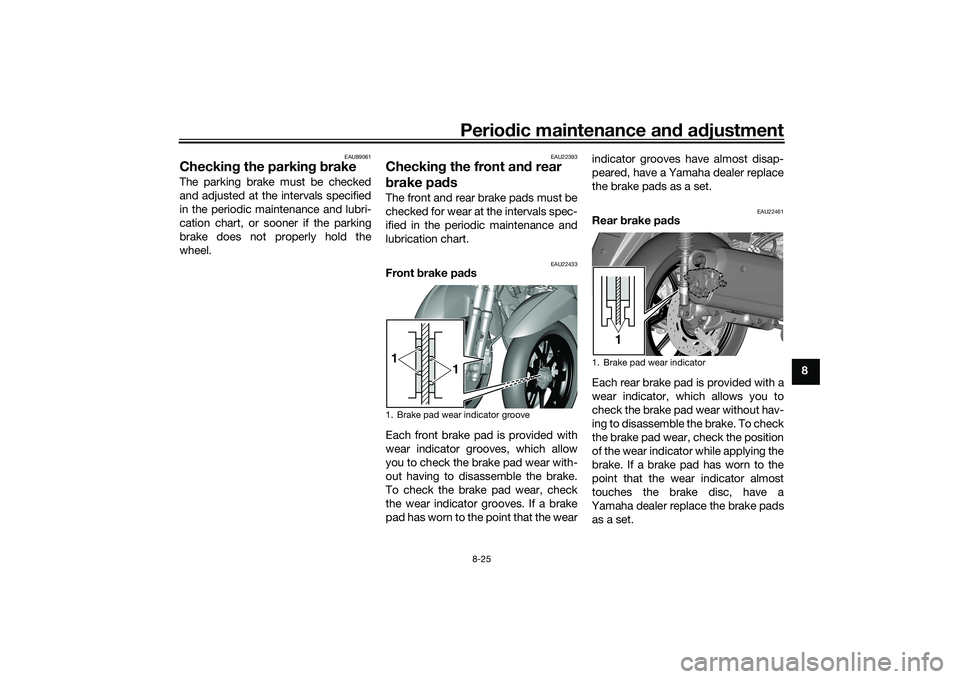
EAU22433
Front brake pad s
Each front brake pad is provided with
wear indicator grooves, which allow
you to check the brake pad wear with-
out having to disassemble the brake.
To check the brake pad wear, check
the wear indicator grooves. If a brake
pad has worn to the point that the wear indicator grooves have almost disap-
peared, have a Yamaha dealer replace
the brake pads as a set.
EAU22461
Rear
brake pa ds
Each rear brake pad is provided with a
wear indicator, which allows you to
check the brake pad wear without hav-
ing to disassemble the brake. To check
the brake pad wear, check the position
of the wear indicator while applying the
brake. If a brake pad has worn to the
point that the wear indicator almost
touches the brake disc, have a
Yamaha dealer replace the brake pads
as a set.
1. Brake pad wear indicator groove1 1
1. Brake pad wear indicator
1
UBX9E0E0.book Page 25 Monday, January 20, 2020 10:54 AM