2020 YAMAHA TRICITY 300 cable
[x] Cancel search: cablePage 8 of 114

Table of contentsSafety information ............................ 1-1
Further safe-riding points ............... 1-5
Description ....................................... 2-1
Left view ......................................... 2-1
Right view ....................................... 2-2
Controls and instruments ............... 2-3
Smart key system ........................... 3-1
Smart key system ........................... 3-1
Operating range of the smart key system......................................... 3-2
Handling of the smart key and mechanical keys ......................... 3-3
Smart key ....................................... 3-4
Replacing the smart key battery..... 3-6
Main switch .................................... 3-7
Stan din g assist ................................. 4-1
Standing assist ............................... 4-1
Instrument an d control functions ... 5-1
Indicator lights and warning
lights............................................ 5-1
Multi-function meter unit ................ 5-3
Handlebar switches ........................ 5-8
Front brake lever .......................... 5-10
Brake pedal .................................. 5-10
Rear brake lever ........................... 5-11
Parking brake lever ....................... 5-12
ABS .............................................. 5-12 Traction control system ................ 5-13
Fuel tank cap ................................ 5-15
Fuel ............................................... 5-16
Fuel tank overflow hose ................ 5-18
Catalytic converter ........................ 5-18
Storage compartment ................... 5-18
Adjusting the shock absorber
assemblies ................................. 5-20
Auxiliary DC jack ........................... 5-20
Sidestand ...................................... 5-21
Ignition circuit cut-off system ....... 5-22
For your safety – pre-operation
checks ............................................... 6-1
Operation an d important ri din g
points ................................................. 7-1
Engine break-in ............................... 7-1
Starting the engine .......................... 7-2
Starting off ...................................... 7-3
Acceleration and deceleration ........ 7-3
Braking ............................................ 7-3
Tips for reducing fuel consumption ................................ 7-4
Parking ............................................ 7-4
Perio dic maintenance an d
a d justment ........................................ 8-1
Tool kit ............................................ 8-2
Periodic maintenance charts .......... 8-3 Periodic maintenance chart for the
emission control system ............. 8-3
General maintenance and lubrication chart .......................... 8-4
Removing and installing the
panel............................................ 8-9
Checking the spark plug............... 8-10
Canister ........................................ 8-11
Engine oil and oil filter element..... 8-12
Why Yamalube.............................. 8-14
Final transmission oil .................... 8-14
Coolant ......................................... 8-15
Air filter and V-belt case air filter elements .................................... 8-17
Checking the throttle grip free play ............................................ 8-21
Valve clearance............................. 8-21
Tires .............................................. 8-22
Cast wheels .................................. 8-23
Checking the front brake lever
free play..................................... 8-24
Checking the rear brake lever free play..................................... 8-24
Checking the parking brake ......... 8-25
Checking the front and rear brake pads ................................ 8-25
Checking the brake fluid level ...... 8-26
Changing the brake fluid .............. 8-27
Checking the V-belt ...................... 8-27
Checking and lubricating the cables ........................................ 8-28UBX9E0E0.book Page 1 Monday, January 20, 2020 10:54 AM
Page 9 of 114

Table of contents
Checking and lubricating the
throttle grip and cable ................8-28
Lubricating the front and rear brake levers................................8-28
Checking and lubricating the
brake pedal ................................8-29
Checking and lubricating the centerstand and sidestand ........8-29
Checking the front fork..................8-30
Checking the steering ...................8-31
Lubricating the steering bearings .....................................8-31
Checking the wheel bearings ........8-31
Battery ...........................................8-32
Replacing the fuses .......................8-33
Vehicle lights .................................8-35
Replacing a turn signal light bulb ............................................8-35
Replacing the license plate light bulb ............................................8-36
Troubleshooting ............................8-36
Troubleshooting chart ...................8-38
Emergency mode .........................8-40
Vehicle care an d stora ge .................9-1
Matte color caution .........................9-1
Care .................................................9-1
Storage ............................................9-3 Specifications
................................. 10-1
Consumer information ................... 11-1
Identification numbers .................. 11-1
Diagnostic connector.................... 11-2
Vehicle data recording .................. 11-2
In dex ................................................ 12-1
UBX9E0E0.book Page 2 Monday, January 20, 2020 10:54 AM
Page 40 of 114

Instrument and control functions
5-9
5 Ri
ght
EAU89310
Dimmer/Pass switch “ / /PASS”
Set this switch to “ ” for the high
beam and to “ ” for the low beam.
To flash the high beam, press the
switch down to “PASS” while the
headlights are on low beam.TIPWhen the switch is set to low beam,
the outer two headlights come on.
When the switch is set to high beam, all
four headlights come on.
EAU12461
Turn si gnal switch “ / ”
To signal a right-hand turn, push this
switch to “ ”. To signal a left-hand
turn, push this switch to “ ”. When
released, the switch returns to the cen-
ter position. To cancel the turn signal
lights, push the switch in after it has re-
turned to the center position.
EAU12501
Horn switch “ ”
Press this switch to sound the horn.
EAU89273
Stan din g assist switch “ ”
To engage the standing assist, press
the switch once when the standing as-
sist indicator light is flashing.
To disengage the standing assist,
press the switch twice.
EAU54213
Stop/Run/Start switch “ / / ”
To crank the engine with the starter,
set this switch to “ ”, and then push
the switch down towards “ ”. See
page 7-2 for starting instructions prior
to starting the engine. Set this switch to “ ” to stop the en-
gine in case of an emergency, such as
when the vehicle overturns or when the
throttle cable is stuck.
EAU79500
Hazar
d switch “ ”
With the main switch in the “ON” posi-
tion, use this switch to turn on the haz-
ard lights (simultaneous flashing of all
turn signal lights).
The hazard lights are used in case of an
emergency or to warn other drivers
when your vehicle is stopped where it
might be a traffic hazard.NOTICE
ECA10062
Do not use the hazard lights for an
exten ded len gth of time with the en-
g ine not runnin g, otherwise the bat-
tery may dischar ge.
EAU88941
“SEL/RES” switch
This switch is used to make setting and
display changes in the multi-function
meter unit. See page 5-3 for more in-
formation.
1. Stop/Run/Start switch “ / / ”
2. Hazard switch “ ”
3. “SEL/RES” switch
12
3
UBX9E0E0.book Page 9 Monday, January 20, 2020 10:54 AM
Page 61 of 114

Periodic maintenance an d a djustment
8-1
8
EAU17246
Periodic inspection, adjustment, and
lubrication will keep your vehicle in the
safest and most efficient condition
possible. Safety is an obligation of the
vehicle owner/operator. The most im-
portant points of vehicle inspection,
adjustment, and lubrication are ex-
plained on the following pages.
The intervals given in the periodic
maintenance charts should be simply
considered as a general guide under
normal riding conditions. However, de-
pending on the weather, terrain, geo-
graphical location, and individual use,
the maintenance intervals may need to
be shortened.
WARNING
EWA10322
Failure to properly maintain the vehi-
cle or performin g maintenance ac-
tivities incorrectly may increase
your risk of injury or death during
service or while usin g the vehicle. If
you are not familiar with vehicle ser-
vice, have a Yamaha d ealer perform
service.
WARNING
EWA15123
Turn off the en gine when performin g
maintenance unless otherwise
specified .
A runnin g en gine has movin g
parts that can catch on b ody
parts or clothin g an d electrical
parts that can cause shocks or
fires.
Runnin g the eng ine while ser-
vicin g can lead to eye injury,
b urns, fire, or car bon monoxi de
poisonin g – possi bly lea din g to
d eath. See pag e 1-2 for more in-
formation a bout car bon monox-
i d e.
WARNING
EWA15461
Brake discs, calipers, drums, an d
linin gs can b ecome very hot during
use. To avoi d possi ble burns, let
b rake components cool before
touching them.
EAU17303
Emission controls not only function to
ensure cleaner air, but are also vital to
proper engine operation and maximum
performance. In the following periodic
maintenance charts, the services relat-
ed to emissions control are grouped
separately. These services require
specialized data, knowledge, and
equipment. Maintenance, replace-
ment, or repair of the emission control
devices and systems may be per-
formed by any repair establishment or
individual that is certified (if applicable).
Yamaha dealers are trained and
equipped to perform these particular
services.
UBX9E0E0.book Page 1 Monday, January 20, 2020 10:54 AM
Page 64 of 114

Periodic maintenance an d a djustment
8-4
8
EAU71353
General maintenance an d lu brication chartNO. ITEM CHECK OR MAINTENANCE JOB ODOMETER READING
ANNUAL
CHECK
1000 km
(600 mi) 10000 km
(6000 mi) 20000 km
(12000 mi) 30000 km
(18000 mi) 40000 km
(24000 mi)
1 *Dia
gnostic system
check • Perform dynamic inspection us-
ing Yamaha diagnostic tool.
• Check the error codes. √√√√√√
2 *Air filter element • Replace. √√
3 *Pre air filter element • Clean. √√
4 *Su
b air filter ele-
ment • Replace.
√√
5 Air filter case check
hose
• Clean.
√√√√√
6 *V-
belt case air filter
element • Clean.
• Replace if necessary.
√√√√√
7 *Front brake • Check operation, fluid level, and
for fluid leakage.
• Replace brake pads if necessary. √√√√√√
8 *Rear brake • Check operation, fluid level, and
for fluid leakage.
• Replace brake pads if necessary. √√√√√√
9 *Brake hoses • Check for cracks or damage.
√√√√√
• Replace. Every 4 years
10 *Brake flui d • Change. Every 2 years
11 *Parkin g b rake • Check operation.
• Check rubber boot.
• Check cable length and adjust if
necessary. √√√√√√
UBX9E0E0.book Page 4 Monday, January 20, 2020 10:54 AM
Page 66 of 114

Periodic maintenance an d a djustment
8-6
8
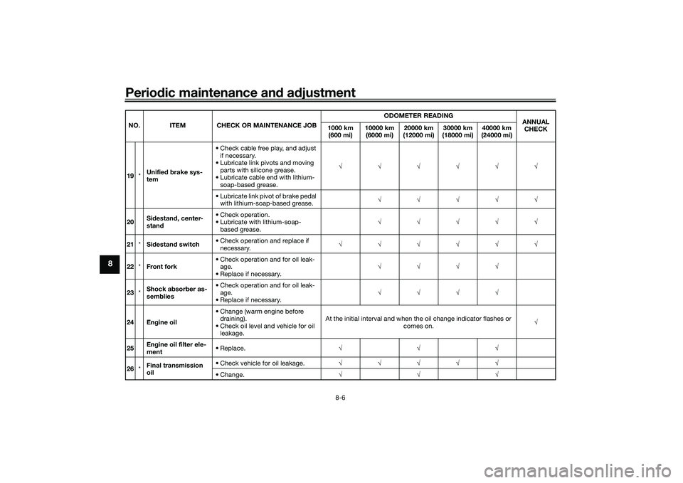
19 *Unifie
d b rake sys-
tem • Check cable free play, and adjust
if necessary.
• Lubricate link pivots and moving parts with silicone grease.
• Lubricate cable end with lithium- soap-based grease. √√√√√√
• Lubricate link pivot of brake pedal with lithium-soap-based grease. √√√√√
20 Si
destan d, center-
stan d • Check operation.
• Lubricate with lithium-soap-
based grease. √√√√√
21 *Sidestan d switch • Check operation and replace if
necessary. √√√√√√
22 *Front fork • Check operation and for oil leak-
age.
• Replace if necessary. √√√√
23 *Shock a
bsor ber as-
sem blies • Check operation and for oil leak-
age.
• Replace if necessary. √√√√
24 En gine oil • Change (warm engine before
draining).
• Check oil level and vehicle for oil leakage. At the initial interval and when the oil change indicator flashes or
comes on. √
25 En
gine oil filter ele-
ment • Replace.
√√√
26 *Final transmission
oil • Check vehicle for oil leakage.
√√√√√
• Change. √√√
NO. ITEM CHECK OR MAINTENANCE JOB
ODOMETER READING
ANNUAL
CHECK
1000 km
(600 mi) 10000 km
(6000 mi) 20000 km
(12000 mi) 30000 km
(18000 mi) 40000 km
(24000 mi)UBX9E0E0.book Page 6 Monday, January 20, 2020 10:54 AM
Page 67 of 114

Periodic maintenance an d a djustment
8-7
8
EAU79370
TIP Engine air filter and V-belt air filter
• This model’s engine air filter is equipped with a disposable oil-coated paper element, which must not be cleaned with compressed air to avoid damaging it.
• The engine air filter element and sub air filter element need to be replaced and the V-belt air filter element needs to be serviced more frequently when riding in unusually wet or dusty areas.27 *Coolin g system • Check coolant level and vehicle
for coolant leakage. √√√√√
• Change. Every 3 years
28 *V-belt • Replace. When the V-belt replacement indicator flashes [every 20000 km (12000 mi)]
29 *Front an
d rear
b rake switches • Check operation.
√√√√√√
30 *Movin
g parts an d
ca bles • Lubricate.
√√√√√
31 *Throttle g
rip hous-
in g an d ca ble • Check operation and free play.
• Adjust the throttle cable free play
if necessary.
• Lubricate the throttle grip housing and cable. √√√√√
32 *Li
ghts, si gnals an d
switches • Check operation.
• Adjust headlight beam.
√√√√√√
NO. ITEM CHECK OR MAINTENANCE JOB
ODOMETER READING
ANNUAL
CHECK
1000 km
(600 mi) 10000 km
(6000 mi) 20000 km
(12000 mi) 30000 km
(18000 mi) 40000 km
(24000 mi)
UBX9E0E0.book Page 7 Monday, January 20, 2020 10:54 AM
Page 88 of 114

Periodic maintenance an d a djustment
8-28
8
EAU23098
Checkin g an d lu bricatin g the
ca blesThe operation of all control cables and
the condition of the cables should be
checked before each ride, and the ca-
bles and cable ends should be lubri-
cated if necessary. If a cable is
damaged or does not move smoothly,
have a Yamaha dealer check or re-
place it. WARNING! Dama ge to the
outer housin g of cab les may result
in internal rustin g an d cause inter-
ference with cab le movement. Re-
place damag ed cab les as soon as
possi ble to prevent unsafe con di-
tions.
[EWA10712] EAU49921
Checkin
g an d lu bricatin g the
throttle grip an d cab leThe operation of the throttle grip
should be checked before each ride. In
addition, the cable should be lubricat-
ed by a Yamaha dealer at the intervals
specified in the periodic maintenance
chart.
EAU23173
Lubricatin g the front an d rear
b rake leversFront brake lever
Rear brake lever
The pivoting points of the front and rear
brake levers must be lubricated at the
intervals specified in the periodic main-
tenance and lubrication chart.
Recommen ded lu bricant:
Yamaha cable lubricant or other
suitable cable lubricant
UBX9E0E0.book Page 28 Monday, January 20, 2020 10:54 AM