2020 YAMAHA TRICITY 300 turn signal
[x] Cancel search: turn signalPage 9 of 114
Table of contents
Checking and lubricating the
throttle grip and cable ................8-28
Lubricating the front and rear brake levers................................8-28
Checking and lubricating the
brake pedal ................................8-29
Checking and lubricating the centerstand and sidestand ........8-29
Checking the front fork..................8-30
Checking the steering ...................8-31
Lubricating the steering bearings .....................................8-31
Checking the wheel bearings ........8-31
Battery ...........................................8-32
Replacing the fuses .......................8-33
Vehicle lights .................................8-35
Replacing a turn signal light bulb ............................................8-35
Replacing the license plate light bulb ............................................8-36
Troubleshooting ............................8-36
Troubleshooting chart ...................8-38
Emergency mode .........................8-40
Vehicle care an d stora ge .................9-1
Matte color caution .........................9-1
Care .................................................9-1
Storage ............................................9-3 Specifications
................................. 10-1
Consumer information ................... 11-1
Identification numbers .................. 11-1
Diagnostic connector.................... 11-2
Vehicle data recording .................. 11-2
In dex ................................................ 12-1
UBX9E0E0.book Page 2 Monday, January 20, 2020 10:54 AM
Page 11 of 114
Safety information
1-2
1
• Know your skills and limits.
Staying within your limits may
help you to avoid an accident.
• We recommend that you prac- tice riding your vehicle where
there is no traffic until you have
become thoroughly familiar with
the vehicle and all of its con-
trols.
Many accidents have been
caused by error of the vehicle op-
erator. A typical error made by the
operator is veering wide on a turn
due to excessive speed or under-
cornering (insufficient lean angle
for the speed).
• Always obey the speed limit and never travel faster than warrant-
ed by road and traffic condi-
tions.
• Always signal before turning or changing lanes. Make sure that
other motorists can see you.
The posture of the operator and
passenger is important for proper
control.
• The operator should keep both hands on the handlebar and
both feet on the operator foot-
rests during operation to main-
tain control of the vehicle.
• The passenger should always hold onto the operator, the seat
strap or grab bar, if equipped,
with both hands and keep both
feet on the passenger footrests.
Never carry a passenger unless
he or she can firmly place both
feet on the passenger footrests.
Never ride under the influence of
alcohol or other drugs.
This vehicle is designed for on-
road use only. It is not suitable for
off-road use.
Protective Apparel
The majority of fatalities from scooter
and motorcycle accidents are the re-
sult of head injuries. The use of a safety
helmet is the single most critical factor
in the prevention or reduction of head
injuries.
Always wear an approved helmet.
Wear a face shield or goggles.
Wind in your unprotected eyes
could contribute to an impairment
of vision that could delay seeing a
hazard.
The use of a jacket, substantial
shoes, trousers, gloves, etc., is ef-
fective in preventing or reducing
abrasions or lacerations.
Never wear loose-fitting clothes,
otherwise they could catch on the
control levers or wheels and cause
injury or an accident.
Always wear protective clothing
that covers your legs, ankles, and
feet. The engine or exhaust sys-
tem become very hot during or af-
ter operation and can cause
burns.
A passenger should also observe
the above precautions.
Avoi d Car bon Monoxi de Poisonin g
All engine exhaust contains carbon
monoxide, a deadly gas. Breathing
carbon monoxide can cause head-
aches, dizziness, drowsiness, nausea,
confusion, and eventually death.
UBX9E0E0.book Page 2 Monday, January 20, 2020 10:54 AM
Page 14 of 114
Safety information
1-5
1appropriate. Refer to page 8-22 for tire
specifications and more information on
replacing your tires.
Transportin
g the Vehicle
Be sure to observe the following in-
structions before transporting the vehi-
cle in another vehicle. Remove all loose items from the
vehicle.
Point the front wheels straight
ahead on the trailer or in the truck
bed, and choke it in a rail to pre-
vent movement.
Secure the vehicle with tie-downs
or suitable straps that are at-
tached to solid parts of the vehi-
cle, such as the frame or upper
front fork triple clamp (and not, for
example, to rubber-mounted han-
dlebars or turn signals, or parts
that could break). Choose the lo-
cation for the straps carefully so
the straps will not rub against
painted surfaces during transport.
The suspension should be com-
pressed somewhat by the tie-
downs, if possible, so that the ve-
hicle will not bounce excessively
during transport.
EAU60590
Further safe-ri din g points Be sure to signal clearly when
making turns.
Braking can be extremely difficult
on a wet road. Avoid hard braking,
because the vehicle could slide.
Apply the brakes slowly when
stopping on a wet surface.
Slow down as you approach a
corner or turn. Once you have
completed a turn, accelerate
slowly.
Be careful when passing parked
cars. A driver might not see you
and open a door in your path.
Railroad crossings, streetcar rails,
iron plates on road construction
sites, and manhole covers be-
come extremely slippery when
wet. Slow down and cross them
with caution. Keep the vehicle up-
right, otherwise it could slide out
from under you.
The brake pads or linings could
get wet when you wash the vehi-
cle. After washing the vehicle,
check the brakes before riding.
UBX9E0E0.book Page 5 Monday, January 20, 2020 10:54 AM
Page 23 of 114
Smart key system
3-5
3
To turn the smart key on or off
Push the smart key button for approxi-
mately 1 second to turn the smart key
on or off. When the smart key is turned
off, the vehicle cannot be operated
even if the smart key is within operating
range. To operate the vehicle, turn the
smart key on and bring it within operat-
ing range.
To check whether the smart key is
turne
d on or off
Push the smart key button to confirm
the current operating status of the
smart key.
If the smart key indicator light: Short flash (0.1 seconds): The
smart key is turned on.
Long flash (0.5 seconds): The
smart key is turned off.
Remote answer- back function
Push the smart key button to operate
the answer-back function remotely.
The beeper will sound twice and all of
the turn signal lights will flash twice.
This feature is convenient for locating
your vehicle in a parking lot and other
areas. Operatin
g ran ge of the answer- back
function
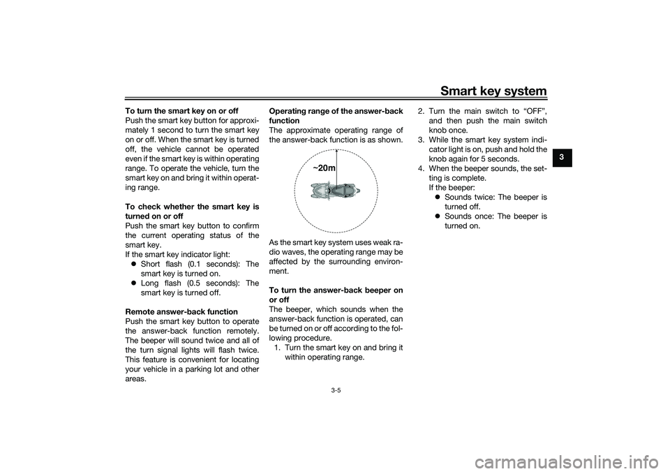
The approximate operating range of
the answer-back function is as shown.
As the smart key system uses weak ra-
dio waves, the operating range may be
affected by the surrounding environ-
ment.
To turn the answer- back beeper on
or off
The beeper, which sounds when the
answer-back function is operated, can
be turned on or off according to the fol-
lowing procedure. 1. Turn the smart key on and bring it within operating range. 2. Turn the main switch to “OFF”,
and then push the main switch
knob once.
3. While the smart key system indi- cator light is on, push and hold the
knob again for 5 seconds.
4. When the beeper sounds, the set- ting is complete.
If the beeper: Sounds twice: The beeper is
turned off.
Sounds once: The beeper is
turned on.
~20m
UBX9E0E0.book Page 5 Monday, January 20, 2020 10:54 AM
Page 26 of 114

Smart key system
3-8
3main switch knob and confirmation
with the smart key has taken place, the
main switch can be turned while the
smart key system indicator light is on
(approximately 4 seconds).
WARNING
EWA18720
Never turn the main switch to
“OFF”, “ ”, or “OPEN” while the ve-
hicle is movin
g. Otherwise the elec-
trical systems will be switche d off,
which may result in loss of control or
an acci dent.TIPDo not push the main switch knob re-
peatedly or turn the main switch back
and forth beyond normal use. Other-
wise, to protect the main switch from
damage, the smart key system will
temporarily disable and the smart key
system indicator light will flash. If this
occurs, wait until the indicator light
stops flashing before operating the
main switch again.The main switch positions are de-
scribed below.
EAU76500
ON (on)
All electrical circuits are supplied with
the power, and the engine can be start-
ed.
To turn the vehicle power on1. Turn the smart key on and bring it
within operating range.
2. Push the main switch knob and the smart key indicator light will
come on for approximately 4 sec-
onds. 3. While the smart key system indi-
cator light is on, turn the main
switch to “ON”. All of the turn sig-
nal lights flash twice and the vehi-
cle power turns on.
TIPIf the vehicle battery voltage is
low, the turn signal lights will not
flash.
See “Emergency mode” on page
8-40 for information on turning the
vehicle power on without the
smart key.
EAU76510
OFF (off)
All electrical systems are off.
1. Push.
2. Turn.1
2
1. Turn.
1
UBX9E0E0.book Page 8 Monday, January 20, 2020 10:54 AM
Page 27 of 114
Smart key system
3-9
3
To turn the vehicle power off
1. With the smart key turned on and
within operating range, turn the
main switch to “OFF”.
2. The turn signal lights flash once and the vehicle power turns off.TIPWhen the main switch is turned to
“OFF” but the smart key cannot be
confirmed (the smart key is either out-
side operation range or has been
turned off), the beeper will sound for 3
seconds and the smart key system in-
dicator light will flash for 30 seconds. During this 30 seconds, the main
switch can be freely operated.
After 30 seconds, the vehicle
power will turn off automatically.
To turn the vehicle power off im-
mediately, push the main switch
knob four times within 2 seconds.
EAU89021
OPEN (open)
Power is supplied to the main switch.
The seat and fuel tank cap lid can be
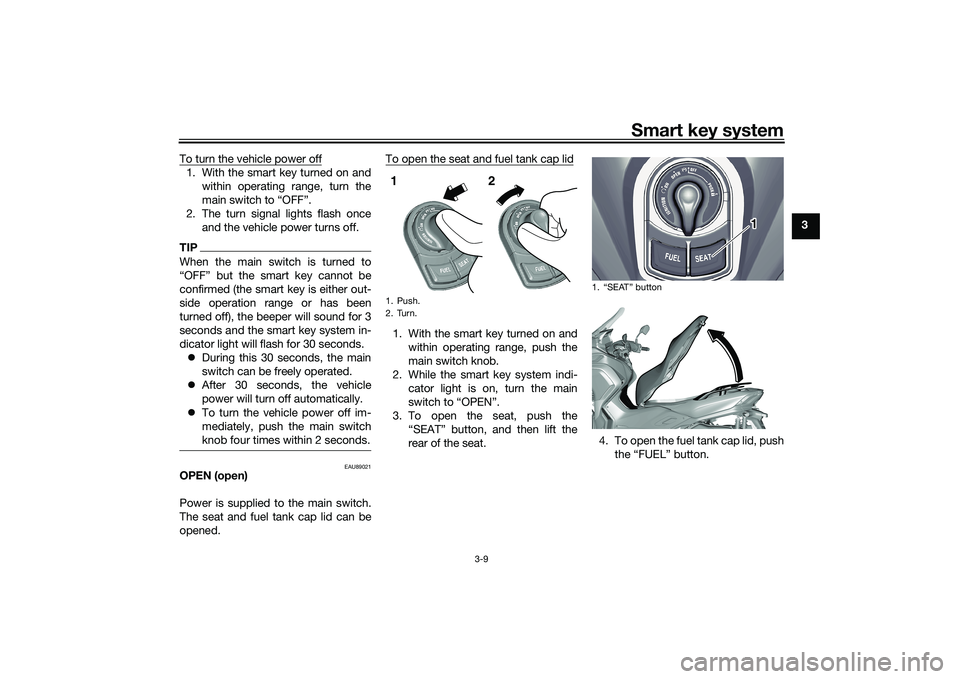
opened. To open the seat and fuel tank cap lid
1. With the smart key turned on and
within operating range, push the
main switch knob.
2. While the smart key system indi- cator light is on, turn the main
switch to “OPEN”.
3. To open the seat, push the “SEAT” button, and then lift the
rear of the seat. 4. To open the fuel tank cap lid, push
the “FUEL” button.1. Push.
2. Turn.1 2
1. “SEAT” button
1
UBX9E0E0.book Page 9 Monday, January 20, 2020 10:54 AM
Page 32 of 114

Instrument and control functions
5-1
5
EAU4939M
In dicator li ghts an d warnin g
li g hts
EAU88900
Turn si gnal in dicator li ghts “ ”
an d“”
Each indicator light will flash when its
corresponding turn signal lights are
flashing.
EAU88910
Hi gh beam in dicator li ght “ ”
This indicator light comes on when the
high beam of the headlight is switched
on.
EAU89121
Parkin g b rake in dicator li ght “ ”
This indicator light comes on when the
parking brake is applied.
EAU88880
Coolant temperature warnin g
li g ht “ ”
This warning light comes on when the
engine is overheating. If this occurs,
stop the engine immediately and allow
the engine to cool. (See page 8-39.)
For vehicles with a radiator fan, the ra-
diator fan(s) automatically switch on or
off according to the coolant tempera-
ture.
TIPWhen the vehicle is turned on, the light
will come on for a few seconds, and
then go off. If the light does not come
on, or if the light remains on, have a
Yamaha dealer check the vehicle.NOTICE
ECA10022
Do not continue to operate the en-
g ine if it is overheatin g.
EAU88920
En gine trou ble warnin g lig ht “ ”
This warning light comes on if a prob-
lem is detected in the engine or other
vehicle control system. If this occurs,
have a Yamaha dealer check the on-
board diagnostic system.TIPWhen the vehicle is turned on, this light
should come on for a few seconds and
then go off. Otherwise, have a Yamaha
dealer check vehicle.
1. ABS warning light “ ”
2. Smart key system indicator light “ ”
3. Left turn signal indicator light “ ”
4. Coolant temperature warning light “ ”
5. Parking brake indicator light “ ”
6. Standing assist indicator light “ ”
7. High beam indicator light “ ”
8. Standing assist warning light “ ”
9. Right turn signal indicator light “ ”
10.Traction control system indicator light “ ”
11.Engine trouble warning light “ ”1
11
2
3
4
5
6
7
8
9
10
UBX9E0E0.book Page 1 Monday, January 20, 2020 10:54 AM
Page 39 of 114

Instrument and control functions
5-8
5
TIPIf only “TCS” is displayed, there is a
communication error within the vehi-
cle. Have a Yamaha dealer check the
vehicle as soon as possible.
EAU89210
Air temperature display
This display shows the air temperature
from –10 °C to 40 °C in 1 °C incre-
ments. The temperature displayed may
vary from the actual ambient tempera-
ture.
The icy road warning indicator “ ” will
flash when the detected temperature is
3 °C or lower.
TIP–10 °C will be displayed even if the am-
bient temperature is lower, and 40 °C
will be displayed even if the ambient
temperature is higher.
EAU89220
Battery volta ge display
This display shows the current charge
state of the battery.TIPIf the battery voltage is less than 9.0 V,
“_ _._” is displayed.
EAU1234P
Han dle bar switchesLeft
1. Air temperature display
2. Icy road warning indicator “ ”
1
2
1. Battery voltage display
1
1. Standing assist switch “ ”
2. Dimmer/Pass switch “ / /PASS”
3. Turn signal switch “ / ”
4. Horn switch “ ”12
3
4
UBX9E0E0.book Page 8 Monday, January 20, 2020 10:54 AM