Page 40 of 114

Instrument and control functions
5-9
5 Ri
ght
EAU89310
Dimmer/Pass switch “ / /PASS”
Set this switch to “ ” for the high
beam and to “ ” for the low beam.
To flash the high beam, press the
switch down to “PASS” while the
headlights are on low beam.TIPWhen the switch is set to low beam,
the outer two headlights come on.
When the switch is set to high beam, all
four headlights come on.
EAU12461
Turn si gnal switch “ / ”
To signal a right-hand turn, push this
switch to “ ”. To signal a left-hand
turn, push this switch to “ ”. When
released, the switch returns to the cen-
ter position. To cancel the turn signal
lights, push the switch in after it has re-
turned to the center position.
EAU12501
Horn switch “ ”
Press this switch to sound the horn.
EAU89273
Stan din g assist switch “ ”
To engage the standing assist, press
the switch once when the standing as-
sist indicator light is flashing.
To disengage the standing assist,
press the switch twice.
EAU54213
Stop/Run/Start switch “ / / ”
To crank the engine with the starter,
set this switch to “ ”, and then push
the switch down towards “ ”. See
page 7-2 for starting instructions prior
to starting the engine. Set this switch to “ ” to stop the en-
gine in case of an emergency, such as
when the vehicle overturns or when the
throttle cable is stuck.
EAU79500
Hazar
d switch “ ”
With the main switch in the “ON” posi-
tion, use this switch to turn on the haz-
ard lights (simultaneous flashing of all
turn signal lights).
The hazard lights are used in case of an
emergency or to warn other drivers
when your vehicle is stopped where it
might be a traffic hazard.NOTICE
ECA10062
Do not use the hazard lights for an
exten ded len gth of time with the en-
g ine not runnin g, otherwise the bat-
tery may dischar ge.
EAU88941
“SEL/RES” switch
This switch is used to make setting and
display changes in the multi-function
meter unit. See page 5-3 for more in-
formation.
1. Stop/Run/Start switch “ / / ”
2. Hazard switch “ ”
3. “SEL/RES” switch
12
3
UBX9E0E0.book Page 9 Monday, January 20, 2020 10:54 AM
Page 59 of 114

Operation and important ri din g points
7-3
7
EAU74640
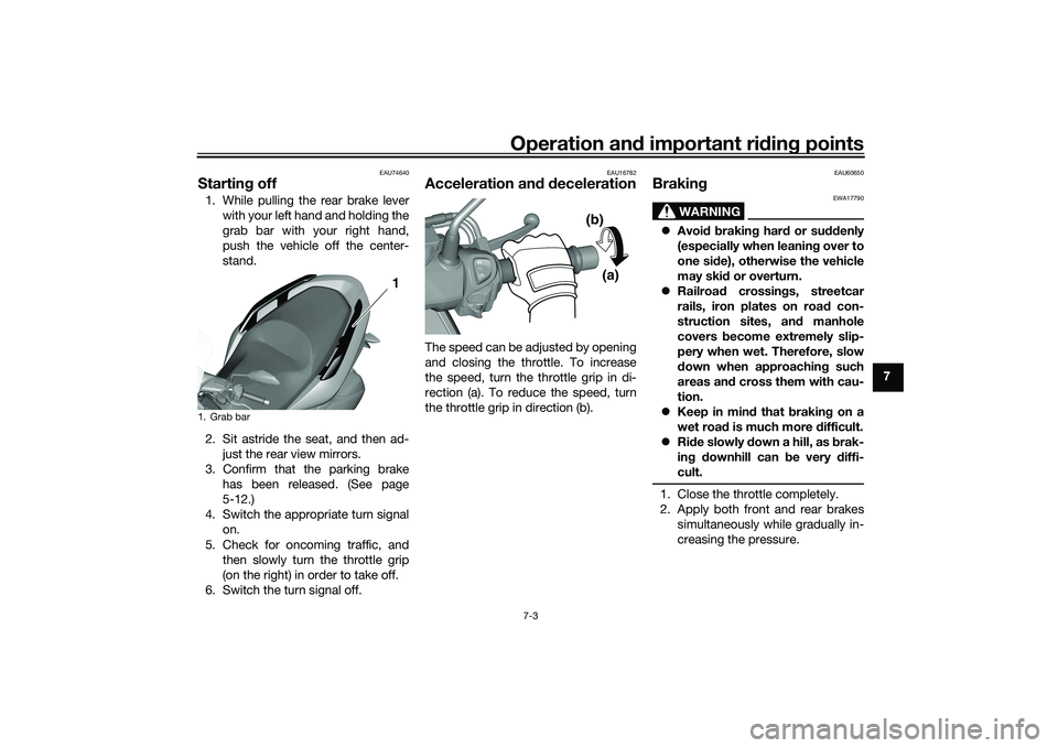
Startin g off1. While pulling the rear brake lever
with your left hand and holding the
grab bar with your right hand,
push the vehicle off the center-
stand.
2. Sit astride the seat, and then ad- just the rear view mirrors.
3. Confirm that the parking brake has been released. (See page
5-12.)
4. Switch the appropriate turn signal on.
5. Check for oncoming traffic, and then slowly turn the throttle grip
(on the right) in order to take off.
6. Switch the turn signal off.
EAU16782
Acceleration an d d ecelerationThe speed can be adjusted by opening
and closing the throttle. To increase
the speed, turn the throttle grip in di-
rection (a). To reduce the speed, turn
the throttle grip in direction (b).
EAU60650
Brakin g
WARNING
EWA17790
Avoi d b rakin g har d or su ddenly
(especially when leanin g over to
one si de), otherwise the vehicle
may ski d or overturn.
Railroa d crossin gs, streetcar
rails, iron plates on road con-
struction sites, an d manhole
covers become extremely slip-
pery when wet. Therefore, slow
d own when approachin g such
areas an d cross them with cau-
tion.
Keep in min d that b raking on a
wet roa d is much more difficult.
Ride slowly d own a hill, as brak-
in g d ownhill can be very diffi-
cult.1. Close the throttle completely.
2. Apply both front and rear brakes simultaneously while gradually in-
creasing the pressure.
1. Grab bar
1 1
(a)
(b)
UBX9E0E0.book Page 3 Monday, January 20, 2020 10:54 AM
Page 94 of 114

Periodic maintenance an d a djustment
8-34
8 If a fuse is blown, replace it as follows.
1. Turn the main switch off and turn off the electrical circuit in ques-
tion.
2. Remove the blown fuse, and then install a new fuse of the specified
amperage. WARNING! Do not
use a fuse of a hi gher ampera ge
ratin g than recommen ded to
avoi d causin g extensive d am-
a g e to the electrical system an d
possi bly a fire.
[EWA15132]
3. Turn the main switch on and turn
on the electrical circuit in question
to check if the device operates.
4. If the fuse immediately blows again, have a Yamaha dealer
check the electrical system.
Specifie d fuses:
Main fuse:
20.0 A
Grip warmer fuse:
7.5 A
Headlight fuse: 7.5 A
Signaling system fuse: 10.0 A
Ignition fuse:
7.5 A
Radiator fan motor fuse: 7.5 A
Backup fuse: 7.5 A
Hazard fuse:
7.5 A
ABS control unit fuse: 7.5 A
ABS motor fuse: 30.0 A
ABS solenoid fuse:
20.0 A
Answer back fuse: 2.0 A
Auxiliary DC jack fuse: 2.0 A
Standing assist fuse:
7.5 A
Standing assist battery fuse: 20.0 A
UBX9E0E0.book Page 34 Monday, January 20, 2020 10:54 AM
Page 95 of 114

Periodic maintenance an d a djustment
8-35
8
EAUN2261
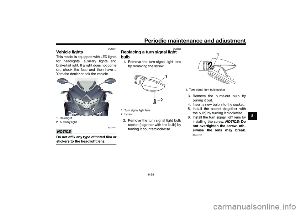
Vehicle li ghtsThis model is equipped with LED lights
for headlights, auxiliary lights and
brake/tail light. If a light does not come
on, check the fuse and then have a
Yamaha dealer check the vehicle.NOTICE
ECA16581
Do not affix any type of tinte d film or
stickers to the head lig ht lens.
EAU62590
Replacin g a turn sig nal light
b ul b1. Remove the turn signal light lens
by removing the screw.
2. Remove the turn signal light bulb socket (together with the bulb) by
turning it counterclockwise. 3. Remove the burnt-out bulb by
pulling it out.
4. Insert a new bulb into the socket.
5. Install the socket (together with the bulb) by turning it clockwise.
6. Install the turn signal light lens by installing the screw. NOTICE: Do
not overti ghten the screw, oth-
erwise the lens may break.
[ECA11192]
1. Headlight
2. Auxiliary light
1 1
1
2
2
1. Turn signal light lens
2. Screw
2
1
1. Turn signal light bulb socket
1
UBX9E0E0.book Page 35 Monday, January 20, 2020 10:54 AM
Page 107 of 114
Specifications
10-2
10
Front brake:Type:
Hydraulic disc brakeRear brake:Type:
Hydraulic single disc brakeFront suspension:Type:
Telescopic forkRear suspension:Type:Unit swingElectrical system:System voltage:12 VBattery:Model:
YTZ8V
Voltage, capacity: 12 V, 7.0 Ah (10 HR)Bul b watta ge:Headlight:
LED
Brake/tail light: LED
Front turn signal light: 10.0 W
Rear turn signal light:
10.0 W
Auxiliary light: LED
License plate light: 5.0 W
UBX9E0E0.book Page 2 Monday, January 20, 2020 10:54 AM
Page 112 of 114

Index
12-2
12
Standing assist ....................................... 4-1
Standing assist indicator light ................ 5-2
Standing assist switch ............................ 5-9
Standing assist warning light .................. 5-2
Starting off .............................................. 7-3
Starting the engine.................................. 7-2
Steering bearings, lubricating ............... 8-31
Steering, checking ................................ 8-31
Stop/Run/Start switch ............................ 5-9
Storage ................................................... 9-3
Storage compartment ........................... 5-18TTachometer ............................................. 5-4
Throttle grip and cable, checking and
lubricating ........................................... 8-28
Throttle grip free play, checking ........... 8-21
Tires ...................................................... 8-22
Tool kit .................................................... 8-2
Traction control system ........................ 5-13
Traction control system display .............. 5-7
Traction control system indicator light ... 5-2
Troubleshooting .................................... 8-36
Troubleshooting chart........................... 8-38
Turn signal indicator lights ...................... 5-1
Turn signal light bulb, replacing............ 8-35
Turn signal switch ................................... 5-9VValve clearance..................................... 8-21
V-belt, checking .................................... 8-27
Vehicle identification number ............... 11-1
Vehicle lights ......................................... 8-35WWheel bearings, checking..................... 8-31
Wheels .................................................. 8-23
YYamalube ............................................. 8-14
UBX9E0E0.book Page 2 Monday, January 20, 2020 10:54 AM