2020 YAMAHA TRICITY 300 oil temperature
[x] Cancel search: oil temperaturePage 36 of 114

Instrument and control functions
5-5
5
EAU89130
Multi-function display
The multi-function display is equipped
with the following: an odometer (ODO)
two tripmeters (TRIP 1 and TRIP 2)
a fuel reserve tripmeter (TRIP F)
an oil change tripmeter (OIL TRIP)
an oil change indicator
a V-belt replacement tripmeter
(BELT TRIP)
a V-belt replacement indicator
an instantaneous fuel consump-
tion display (km/L, L/100 km, or
MPG)
an average fuel consumption dis-
play (AVE_ _._ km/L, AVE_ _._
L/100 km, or AVE_ _ _._ MPG)
a traction control system display
(TCS)
an air temperature display (AIR)
a battery voltage display (VOLT)
Push the “RES” switch to change the
display in the following order:
ODO → TRIP 1 → TRIP 2 → TRIP F →
km/L, L/100 km or MPG → AVE_ _._
km/L, AVE_ _._ L/100 km or AVE_ _ _._
MPG → AIR → VOLT → TCS → OIL
TRIP → BELT TRIP → ODO
TIP The fuel reserve tripmeter appears
only when you are low on fuel.
Push the “SEL” switch to change
the display in the reverse order.
EAU86890
Odometer
The odometer shows the total distance
traveled by the vehicle.TIPThe odometer will lock at 999999 and
cannot be reset.
EAU89140
Tripmeters
The tripmeters show the distance trav-
eled since they were last reset.
To reset a tripmeter, change the dis-
play to the tripmeter you want to reset,
and then push the “RES” switch until it
is reset.TIPThe tripmeters will reset and continue
counting after 9999.9 is reached.
EAU89150
Fuel reserve tripmeter
If the last segment of the fuel meter
starts flashing, the display automati-
cally changes to the fuel reserve trip-
meter “TRIP F” and starts counting the
distance traveled from that point.
To reset the fuel reserve tripmeter,
push the “RES” switch until it is reset.TIPIf you do not reset the fuel reserve trip-
meter manually, it will reset automati-
cally and disappear from the display
after refueling and traveling 5 km (3 mi).
1. Multi-function display
1
UBX9E0E0.book Page 5 Monday, January 20, 2020 10:54 AM
Page 75 of 114

Periodic maintenance an d a djustment
8-15
8
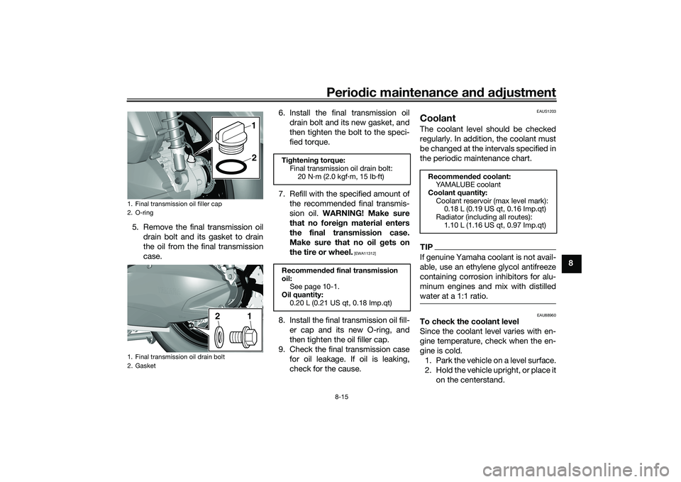
5. Remove the final transmission oil
drain bolt and its gasket to drain
the oil from the final transmission
case. 6. Install the final transmission oil
drain bolt and its new gasket, and
then tighten the bolt to the speci-
fied torque.
7. Refill with the specified amount of the recommended final transmis-
sion oil. WARNING! Make sure
that no forei gn material enters
the final transmission case.
Make sure that no oil gets on
the tire or wheel.
[EWA11312]
8. Install the final transmission oil fill- er cap and its new O-ring, and
then tighten the oil filler cap.
9. Check the final transmission case for oil leakage. If oil is leaking,
check for the cause.
EAUS1203
CoolantThe coolant level should be checked
regularly. In addition, the coolant must
be changed at the intervals specified in
the periodic maintenance chart.TIPIf genuine Yamaha coolant is not avail-
able, use an ethylene glycol antifreeze
containing corrosion inhibitors for alu-
minum engines and mix with distilled
water at a 1:1 ratio.
EAU88960
To check the coolant level
Since the coolant level varies with en-
gine temperature, check when the en-
gine is cold.1. Park the vehicle on a level surface.
2. Hold the vehicle upright, or place it on the centerstand.
1. Final transmission oil filler cap
2. O-ring
1. Final transmission oil drain bolt
2. Gasket
1
21
2
Ti ghtenin g torque:
Final transmission oil drain bolt: 20 N·m (2.0 kgf·m, 15 lb·ft)
Recommen ded final transmission
oil: See page 10-1.
Oil quantity: 0.20 L (0.21 US qt, 0.18 Imp.qt)
Recommen ded coolant:
YAMALUBE coolant
Coolant quantity: Coolant reservoir (max level mark): 0.18 L (0.19 US qt, 0.16 Imp.qt)
Radiator (including all routes): 1.10 L (1.16 US qt, 0.97 Imp.qt)
UBX9E0E0.book Page 15 Monday, January 20, 2020 10:54 AM
Page 111 of 114

12-1
12
Index
AABS....................................................... 5-12
ABS warning light ................................... 5-2
Acceleration and deceleration ................ 7-3
Air filter and V-belt case air filter
elements ............................................. 8-17
Air temperature display .......................... 5-8
Auxiliary DC jack .................................. 5-20BBattery .................................................. 8-32
Brake fluid, changing............................ 8-27
Brake fluid level, checking.................... 8-26
Brake lever, front .................................. 5-10
Brake lever, rear ................................... 5-11
Brake levers, lubricating ....................... 8-28
Brake pedal .......................................... 5-10
Brake pedal, checking and lubricating........................................... 8-29
Braking ................................................... 7-3CCables, checking and lubricating ......... 8-28
Canister ................................................ 8-11
Care ........................................................ 9-1
Catalytic converter ............................... 5-18
Centerstand and sidestand, checking and lubricating ................................... 8-29
Clock ...................................................... 5-4
Coolant ................................................. 8-15
Coolant temperature warning light ......... 5-1DData recording, vehicle......................... 11-2
Diagnostic connector ........................... 11-2
Dimmer/Pass switch............................... 5-9
Display units, switching .......................... 5-3
EEmergency mode ................................. 8-40
Engine break-in ...................................... 7-1
Engine oil and oil filter element ............ 8-12
Engine overheating .............................. 8-39
Engine serial number ........................... 11-1
Engine trouble warning light .................. 5-1FFinal transmission oil............................ 8-14
Front and rear brake pads, checking ... 8-25
Front brake lever free play, checking ... 8-24
Front fork, checking ............................. 8-30
Fuel ...................................................... 5-16
Fuel consumption, tips for reducing ...... 7-4
Fuel meter .............................................. 5-4
Fuel tank cap........................................ 5-15
Fuel tank overflow hose ....................... 5-18
Fuses, replacing ................................... 8-33HHandlebar switches ............................... 5-8
Hazard switch ........................................ 5-9
High beam indicator light ....................... 5-1
Horn switch ............................................ 5-9IIdentification numbers ......................... 11-1
Ignition circuit cut-off system .............. 5-22
Indicator lights and warning lights ......... 5-1KKey, handling of smart and mechanical keys...................................................... 3-3LLicense plate light bulb, replacing ....... 8-36MMain switch ............................................ 3-7 Maintenance and lubrication, periodic ... 8-4
Maintenance, emission control
system .................................................. 8-3
Matte color, caution................................ 9-1
Model label ........................................... 11-1
Multi-function display ............................. 5-5
Multi-function meter unit ........................ 5-3
OOperating range of the smart key system .................................................. 3-2PPanel, removing and installing ................ 8-9
Parking.................................................... 7-4
Parking brake, checking ....................... 8-25
Parking brake indicator light ................... 5-1
Parking brake lever ............................... 5-12
Part locations.......................................... 2-1RRear brake lever free play, checking .... 8-24SSafe-riding points ................................... 1-5
Safety information................................... 1-1
SEL/RES switch ...................................... 5-9
Shock absorber assemblies, adjusting ............................................. 5-20
Sidestand.............................................. 5-21
Smart key................................................ 3-4
Smart key battery, replacing................... 3-6
Smart key system ................................... 3-1
Smart key system indicator light ............ 5-2
Smart key system, troubleshooting ...... 8-37
Spark plug, checking ............................ 8-10
Specifications ....................................... 10-1
Speedometer .......................................... 5-3
UBX9E0E0.book Page 1 Monday, January 20, 2020 10:54 AM