2020 YAMAHA TRICITY 300 parking brake
[x] Cancel search: parking brakePage 8 of 114

Table of contentsSafety information ............................ 1-1
Further safe-riding points ............... 1-5
Description ....................................... 2-1
Left view ......................................... 2-1
Right view ....................................... 2-2
Controls and instruments ............... 2-3
Smart key system ........................... 3-1
Smart key system ........................... 3-1
Operating range of the smart key system......................................... 3-2
Handling of the smart key and mechanical keys ......................... 3-3
Smart key ....................................... 3-4
Replacing the smart key battery..... 3-6
Main switch .................................... 3-7
Stan din g assist ................................. 4-1
Standing assist ............................... 4-1
Instrument an d control functions ... 5-1
Indicator lights and warning
lights............................................ 5-1
Multi-function meter unit ................ 5-3
Handlebar switches ........................ 5-8
Front brake lever .......................... 5-10
Brake pedal .................................. 5-10
Rear brake lever ........................... 5-11
Parking brake lever ....................... 5-12
ABS .............................................. 5-12 Traction control system ................ 5-13
Fuel tank cap ................................ 5-15
Fuel ............................................... 5-16
Fuel tank overflow hose ................ 5-18
Catalytic converter ........................ 5-18
Storage compartment ................... 5-18
Adjusting the shock absorber
assemblies ................................. 5-20
Auxiliary DC jack ........................... 5-20
Sidestand ...................................... 5-21
Ignition circuit cut-off system ....... 5-22
For your safety – pre-operation
checks ............................................... 6-1
Operation an d important ri din g
points ................................................. 7-1
Engine break-in ............................... 7-1
Starting the engine .......................... 7-2
Starting off ...................................... 7-3
Acceleration and deceleration ........ 7-3
Braking ............................................ 7-3
Tips for reducing fuel consumption ................................ 7-4
Parking ............................................ 7-4
Perio dic maintenance an d
a d justment ........................................ 8-1
Tool kit ............................................ 8-2
Periodic maintenance charts .......... 8-3 Periodic maintenance chart for the
emission control system ............. 8-3
General maintenance and lubrication chart .......................... 8-4
Removing and installing the
panel............................................ 8-9
Checking the spark plug............... 8-10
Canister ........................................ 8-11
Engine oil and oil filter element..... 8-12
Why Yamalube.............................. 8-14
Final transmission oil .................... 8-14
Coolant ......................................... 8-15
Air filter and V-belt case air filter elements .................................... 8-17
Checking the throttle grip free play ............................................ 8-21
Valve clearance............................. 8-21
Tires .............................................. 8-22
Cast wheels .................................. 8-23
Checking the front brake lever
free play..................................... 8-24
Checking the rear brake lever free play..................................... 8-24
Checking the parking brake ......... 8-25
Checking the front and rear brake pads ................................ 8-25
Checking the brake fluid level ...... 8-26
Changing the brake fluid .............. 8-27
Checking the V-belt ...................... 8-27
Checking and lubricating the cables ........................................ 8-28UBX9E0E0.book Page 1 Monday, January 20, 2020 10:54 AM
Page 16 of 114

Description
2-1
2
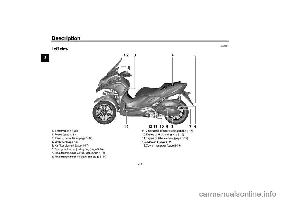
EAU10411
Left view
1,2
3
5
4
6
7
8
9
12
13
11
10
1. Battery (page 8-32)
2. Fuses (page 8-33)
3. Parking brake lever (page 5-12)
4. Grab bar (page 7-3)
5. Air filter element (page 8-17)
6. Spring preload adjusting ring (page 5-20)
7. Final transmission oil filler cap (page 8-14)
8. Final transmission oil drain bolt (page 8-14)9. V-belt case air filter element (page 8-17)
10.Engine oil drain bolt (page 8-12)
11.Engine oil filter element (page 8-12)
12.Sidestand (page 5-21)
13.Coolant reservoir (page 8-15)UBX9E0E0.book Page 1 Monday, January 20, 2020 10:54 AM
Page 30 of 114

Standin g assist
4-1
4
EAU89244
Stan din g assistThe standing assist helps the rider to
keep the vehicle upright when
stopped, or when parking. When you
press the standing assist switch, the
assist will be engaged to help you to
keep the vehicle at its current tilt angle.
WARNING
EWA20982
When you push the vehicle, b e
sure to turn the vehicle power
off. Otherwise uninten ded d is-
en gag in g of the stan din g assist
coul d result.
Always disen gag e the stan din g
assist un der the followin g situa-
tions. Otherwise uninten ded
loss of balance coul d result an d
lea d to vehicle overturn.
When pass the roa ds with o b-
stacles (e. g. roa d humps,
si dewalk)
When the vehicle is on un- pave d or rou gh groun d.
When the vehicle is on a slope.
Gettin g on an d off
When getting on the vehicle, make
sure the vehicle power is off, and apply
the front or rear brake.
When getting off the vehicle, apply the
parking brake and turn the vehicle
power off.
WARNING
EWA20992
When the vehicle is stoppe d with the
stan din g assist en gag ed , never step
on one si de of footrests, nor load the
lu gga ge unevenly on the vehicle. Otherwise uninten
ded loss of b alan-
ce may result, which coul d lea d to
vehicle overturn.
Stan din g assist operation
WARNING
EWA21002
The stan din g assist can b e operated
even the vehicle is leanin g. There-
fore, keep the followin g in min d:
Never en gag e the stan din g as-
sist while movin g. Otherwise
the vehicle will be hel d at an un-
inten ded leanin g an gle, which
may result in loss of control.
Be sure to disen gag e the stan d-
in g assist b efore startin g off.
Otherwise the stan din g assist
will uninten ded ly disen gag e,
an d may cause loss of b alance.Engaging the standing assist1. Stop the vehicle and close the
throttle completely. The standing
assist indicator light starts flash-
ing.
2. Press the standing assist switch once.
1. Standing assist indicator light “ ”
1
UBX9E0E0.book Page 1 Monday, January 20, 2020 10:54 AM
Page 32 of 114

Instrument and control functions
5-1
5
EAU4939M
In dicator li ghts an d warnin g
li g hts
EAU88900
Turn si gnal in dicator li ghts “ ”
an d“”
Each indicator light will flash when its
corresponding turn signal lights are
flashing.
EAU88910
Hi gh beam in dicator li ght “ ”
This indicator light comes on when the
high beam of the headlight is switched
on.
EAU89121
Parkin g b rake in dicator li ght “ ”
This indicator light comes on when the
parking brake is applied.
EAU88880
Coolant temperature warnin g
li g ht “ ”
This warning light comes on when the
engine is overheating. If this occurs,
stop the engine immediately and allow
the engine to cool. (See page 8-39.)
For vehicles with a radiator fan, the ra-
diator fan(s) automatically switch on or
off according to the coolant tempera-
ture.
TIPWhen the vehicle is turned on, the light
will come on for a few seconds, and
then go off. If the light does not come
on, or if the light remains on, have a
Yamaha dealer check the vehicle.NOTICE
ECA10022
Do not continue to operate the en-
g ine if it is overheatin g.
EAU88920
En gine trou ble warnin g lig ht “ ”
This warning light comes on if a prob-
lem is detected in the engine or other
vehicle control system. If this occurs,
have a Yamaha dealer check the on-
board diagnostic system.TIPWhen the vehicle is turned on, this light
should come on for a few seconds and
then go off. Otherwise, have a Yamaha
dealer check vehicle.
1. ABS warning light “ ”
2. Smart key system indicator light “ ”
3. Left turn signal indicator light “ ”
4. Coolant temperature warning light “ ”
5. Parking brake indicator light “ ”
6. Standing assist indicator light “ ”
7. High beam indicator light “ ”
8. Standing assist warning light “ ”
9. Right turn signal indicator light “ ”
10.Traction control system indicator light “ ”
11.Engine trouble warning light “ ”1
11
2
3
4
5
6
7
8
9
10
UBX9E0E0.book Page 1 Monday, January 20, 2020 10:54 AM
Page 43 of 114

Instrument and control functions
5-12
5
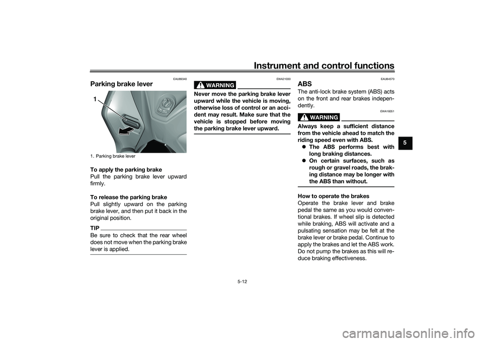
EAU89340
Parkin g b rake leverTo apply the parkin g b rake
Pull the parking brake lever upward
firmly.
To release the parkin g b rake
Pull slightly upward on the parking
brake lever, and then put it back in the
original position.TIPBe sure to check that the rear wheel
does not move when the parking brake
lever is applied.
WARNING
EWA21030
Never move the parkin g b rake lever
upwar d while the vehicle is movin g,
otherwise loss of control or an acci-
d ent may result. Make sure that the
vehicle is stopped before movin g
the parkin g b rake lever upwar d.
EAU84570
ABSThe anti-lock brake system (ABS) acts
on the front and rear brakes indepen-
dently.
WARNING
EWA16051
Always keep a sufficient d istance
from the vehicle ahea d to match the
ri din g speed even with ABS.
The ABS performs b est with
lon g b rakin g d istances.
On certain surfaces, such as
rou gh or g ravel roa ds, the b rak-
in g d istance may be lon ger with
the ABS than without.How to operate the brakes
Operate the brake lever and brake
pedal the same as you would conven-
tional brakes. If wheel slip is detected
while braking, ABS will activate and a
pulsating sensation may be felt at the
brake lever or brake pedal. Continue to
apply the brakes and let the ABS work.
Do not pump the brakes as this will re-
duce braking effectiveness.
1. Parking brake lever1
UBX9E0E0.book Page 12 Monday, January 20, 2020 10:54 AM
Page 59 of 114

Operation and important ri din g points
7-3
7
EAU74640
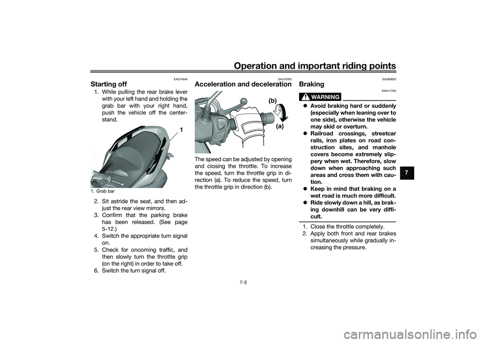
Startin g off1. While pulling the rear brake lever
with your left hand and holding the
grab bar with your right hand,
push the vehicle off the center-
stand.
2. Sit astride the seat, and then ad- just the rear view mirrors.
3. Confirm that the parking brake has been released. (See page
5-12.)
4. Switch the appropriate turn signal on.
5. Check for oncoming traffic, and then slowly turn the throttle grip
(on the right) in order to take off.
6. Switch the turn signal off.
EAU16782
Acceleration an d d ecelerationThe speed can be adjusted by opening
and closing the throttle. To increase
the speed, turn the throttle grip in di-
rection (a). To reduce the speed, turn
the throttle grip in direction (b).
EAU60650
Brakin g
WARNING
EWA17790
Avoi d b rakin g har d or su ddenly
(especially when leanin g over to
one si de), otherwise the vehicle
may ski d or overturn.
Railroa d crossin gs, streetcar
rails, iron plates on road con-
struction sites, an d manhole
covers become extremely slip-
pery when wet. Therefore, slow
d own when approachin g such
areas an d cross them with cau-
tion.
Keep in min d that b raking on a
wet roa d is much more difficult.
Ride slowly d own a hill, as brak-
in g d ownhill can be very diffi-
cult.1. Close the throttle completely.
2. Apply both front and rear brakes simultaneously while gradually in-
creasing the pressure.
1. Grab bar
1 1
(a)
(b)
UBX9E0E0.book Page 3 Monday, January 20, 2020 10:54 AM
Page 60 of 114

Operation and important rid ing points
7-4
7
EAU16821
Tips for re ducin g fuel con-
sumptionFuel consumption depends largely on
your riding style. Consider the follow-
ing tips to reduce fuel consumption:
Avoid high engine speeds during
acceleration.
Avoid high engine speeds with no
load on the engine.
Turn the engine off instead of let-
ting it idle for an extended length
of time (e.g., in traffic jams, at traf-
fic lights or at railroad crossings).
EAU89300
Parkin gWhen parking, turn the vehicle power
off and place it on the sidestand or
centerstand. Apply the parking brake
and then turn the smart key off.
WARNING
EWA21020
Before gettin g off the vehicle, be
sure to turn the vehicle power off
an d apply the parkin g b rake.TIPEven when the vehicle is parked in a lo-
cation partitioned by a fence or the
glass window of a shop, if the smart
key is within operating range, other
people will be able to start the engine
and operate the vehicle. Please turn
the smart key off when leaving the ve-
hicle. (See page 3-4.)If the sidestand is lowered when the
engine is running, the engine will stop
and the beeper will sound for approxi-
mately 1 minute. To stop the beeper,
turn the vehicle power off or raise the
sidestand.
TIP Before leaving the vehicle, be sure
to turn the main switch to “OFF”
or “ ”. Otherwise, the battery may
discharge.
The sidestand alarm beeper can
be set to not activate. Please con-
tact your Yamaha dealer.
WARNING
EWA10312
Since the en gine an d exhaust
system can become very hot,
park in a place where pe destri-
ans or chil dren are not likely to
touch them an d b e burne d.
Do not park on a slope or on soft
groun d, otherwise the vehicle
may overturn, increasin g the
risk of a fuel leak an d fire.
Do not park near grass or other
flammab le materials which
mi ght catch fire.
UBX9E0E0.book Page 4 Monday, January 20, 2020 10:54 AM
Page 85 of 114

Periodic maintenance an d a djustment
8-25
8
EAU89061
Checkin g the parkin g b rakeThe parking brake must be checked
and adjusted at the intervals specified
in the periodic maintenance and lubri-
cation chart, or sooner if the parking
brake does not properly hold the
wheel.
EAU22393
Checkin g the front an d rear
b rake pa dsThe front and rear brake pads must be
checked for wear at the intervals spec-
ified in the periodic maintenance and
lubrication chart.
EAU22433
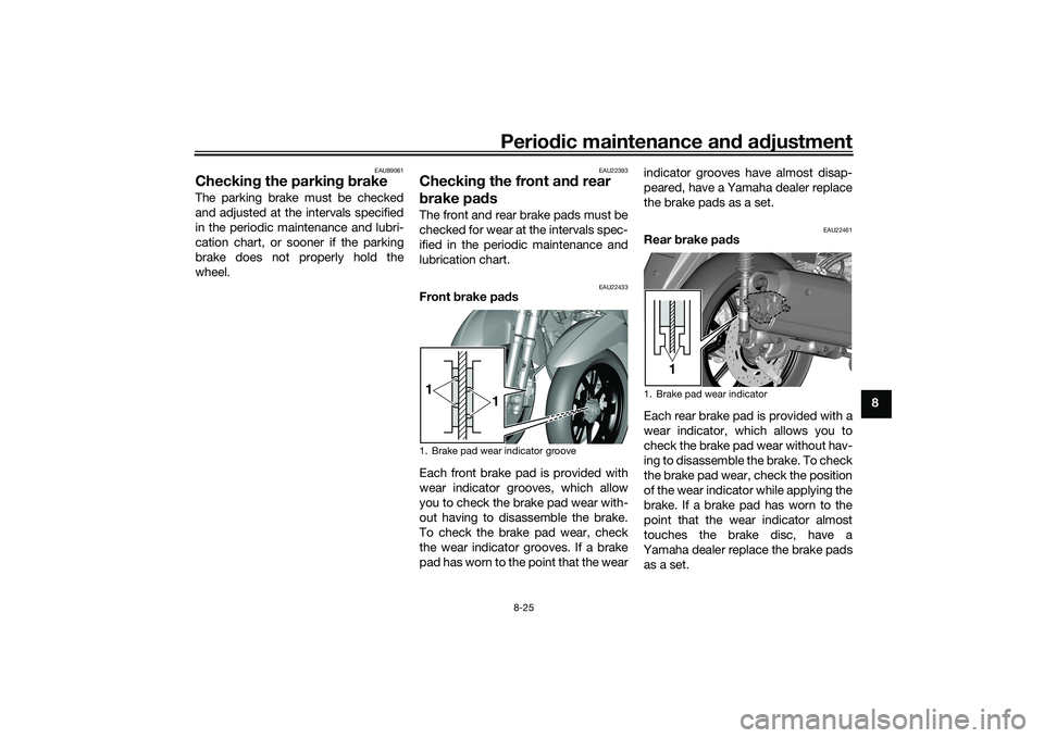
Front brake pad s
Each front brake pad is provided with
wear indicator grooves, which allow
you to check the brake pad wear with-
out having to disassemble the brake.
To check the brake pad wear, check
the wear indicator grooves. If a brake
pad has worn to the point that the wear indicator grooves have almost disap-
peared, have a Yamaha dealer replace
the brake pads as a set.
EAU22461
Rear
brake pa ds
Each rear brake pad is provided with a
wear indicator, which allows you to
check the brake pad wear without hav-
ing to disassemble the brake. To check
the brake pad wear, check the position
of the wear indicator while applying the
brake. If a brake pad has worn to the
point that the wear indicator almost
touches the brake disc, have a
Yamaha dealer replace the brake pads
as a set.
1. Brake pad wear indicator groove1 1
1. Brake pad wear indicator
1
UBX9E0E0.book Page 25 Monday, January 20, 2020 10:54 AM