Page 57 of 96

Periodic maintenance and adjustment
6-13
6
EAUM2391
Replacing the air filter ele-
ment and cleaning the check
hose
The air filter element should be re-
placed at the intervals specified in the
periodic maintenance and lubrication
chart. Have a Yamaha dealer replace
the air filter element more frequently if
you are riding in unusually wet or dusty
areas. In addition, the air filter check
hose must be frequently checked and
cleaned if necessary.
To clean the air filter check hose
1. Check the hose on the side of the
air filter case for accumulated dirt
or water.
2. If dirt or water is visible, remove
the hose, clean it, and then install
it.
EAU34302
Adjusting the engine idling
speed
The engine idling speed must be
checked and, if necessary, adjusted as
follows at the intervals specified in the
periodic maintenance and lubrication
chart.
The engine should be warm before
making this adjustment.
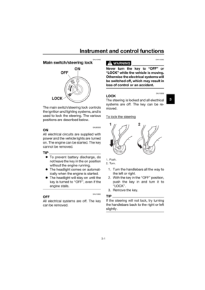
Check the engine idling speed and, if
necessary, adjust it to specification by
turning the idle adjusting screw. To in-
crease the engine idling speed, turn the
screw in direction (a). To decrease the
engine idling speed, turn the screw in
direction (b).
TIP
If the specified idling speed cannot be
obtained as described above, have a
Yamaha dealer make the adjustment.
1. Air filter check hose
ZAUM173911. Idle adjusting screw
Engine idling speed:
1250–1550 r/min
1
(b)
(a)
UB6GE0E0.book Page 13 Wednesday, August 28, 2019 11:11 AM
Page 58 of 96
Periodic maintenance and adjustment
6-14
6
EAU48434
Adjusting the throttle grip free
play
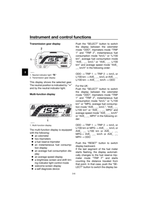
Measure the throttle grip free play as
shown.
Periodically check the throttle grip free
play and, if necessary, adjust it as fol-
lows.
TIP
The engine idling speed must be cor-
rectly adjusted before checking and
adjusting the throttle grip free play.
1. Slide the rubber cover back.
2. Loosen the locknut.
3. To increase the throttle grip free
play, turn the adjusting nut in di-
rection (a). To decrease the throt-
tle grip free play, turn the adjusting
nut in direction (b).4. Tighten the locknut and then slide
the rubber cover to its original po-
sition.
1. Throttle grip free play
Throttle grip free play:
3.0–5.0 mm (0.12–0.20 in)
1
1. Adjusting nut
2. Locknut
1
2
(a)
(b)
UB6GE0E0.book Page 14 Wednesday, August 28, 2019 11:11 AM
Page 59 of 96

Periodic maintenance and adjustment
6-15
6
EAU21403
Valve clearance
The valves are an important engine
component, and since valve clearance
changes with use, they must be
checked and adjusted at the intervals
specified in the periodic maintenance
chart. Unadjusted valves can result in
improper air-fuel mixture, engine
noise, and eventually engine damage.
To prevent this from occurring, have
your Yamaha dealer check and adjust
the valve clearance at regular intervals.
TIP
This service must be performed when
the engine is cold.
EAU77621
Tires
Tires are the only contact between the
vehicle and the road. Safety in all con-
ditions of riding depends on a relatively
small area of road contact. Therefore, it
is essential to maintain the tires in good
condition at all times and replace them
at the appropriate time with the speci-
fied tires.
Tire air pressure
The tire air pressure should be
checked and, if necessary, adjusted
before each ride.
WARNING
EWA10504
Operation of this vehicle with im-
proper tire pressure may cause se-
vere injury or death from loss of
control.
The tire air pressure must be
checked and adjusted on cold
tires (i.e., when the temperature
of the tires equals the ambient
temperature).
The tire air pressure must be
adjusted in accordance with the
riding speed and with the total
weight of rider, passenger, car-
go, and accessories approved
for this model.
UB6GE0E0.book Page 15 Wednesday, August 28, 2019 11:11 AM
Page 60 of 96

Periodic maintenance and adjustment
6-16
6
WARNING
EWA10512
Never overload your vehicle. Opera-
tion of an overloaded vehicle could
cause an accident.
Tire inspection
The tires must be checked before each
ride. If the center tread depth reaches
the specified limit, if the tire has a nail
or glass fragments in it, or if the side-
wall is cracked, have a Yamaha dealer
replace the tire immediately.
TIP
The tire tread depth limits may differ
from country to country. Always com-
ply with the local regulations.
WARNING
EWA10472
Have a Yamaha dealer replace
excessively worn tires. Besides
being illegal, operating the vehi-
cle with excessively worn tires
decreases riding stability and
can lead to loss of control.
The replacement of all wheel
and brake-related parts, includ-
ing the tires, should be left to a
Yamaha dealer, who has the
necessary professional knowl-
edge and experience to do so.
Ride at moderate speeds after
changing a tire since the tire
surface must first be “broken
in” for it to develop its optimal
characteristics.
Tire information
Cold tire air pressure:
1 person:
Front:
200 kPa (2.00 kgf/cm², 29 psi)
Rear:
220 kPa (2.20 kgf/cm², 32 psi)
2 persons:
Front:
200 kPa (2.00 kgf/cm², 29 psi)
Rear:
220 kPa (2.20 kgf/cm², 32 psi)
Maximum load:
Vehicle:
180 kg (397 lb)
The vehicle’s maximum load is the
combined weight of the rider, pas-
senger, cargo, and any accessories.
1. Tire sidewall
2. Tire tread depth
Minimum tire tread depth (front and
rear):
1.6 mm (0.06 in)
1. Tire air valve
2. Tire air valve core
3. Tire air valve cap with seal
123
UB6GE0E0.book Page 16 Wednesday, August 28, 2019 11:11 AM
Page 61 of 96

Periodic maintenance and adjustment
6-17
6 This model is equipped with tubeless
tires and tire air valves.
Tires age, even if they have not been
used or have only been used occasion-
ally. Cracking of the tread and sidewall
rubber, sometimes accompanied by
carcass deformation, is an evidence of
ageing. Old and aged tires shall be
checked by tire specialists to ascertain
their suitability for further use.
WARNING
EWA16101
The front and rear tires should
be of the same make and de-
sign, otherwise the handling
characteristics of the vehicle
may be different, which could
lead to an accident.
Always make sure that the valve
caps are securely installed to
prevent air pressure leakage.
Use only the tire valves and
valve cores listed below to
avoid tire deflation during a ride.
After extensive tests, only the tires list-
ed below have been approved for this
model by Yamaha.
Front tire:
Size:
100/80-17M/C 52S
Manufacturer/model:
MICHELIN PILOT STREET
Tire air valve:
TR412
Valve core:
V3002 (original)
Rear tire:
Size:
140/70-17M/C 66S
Manufacturer/model:
MICHELIN PILOT STREET
Tire air valve:
TR412
Valve core:
V3002 (original)
UB6GE0E0.book Page 17 Wednesday, August 28, 2019 11:11 AM
Page 62 of 96

Periodic maintenance and adjustment
6-18
6
EAU21963
Cast wheels
To maximize the performance, durabil-
ity, and safe operation of your vehicle,
note the following points regarding the
specified wheels.
The wheel rims should be
checked for cracks, bends, warp-
age or other damage before each
ride. If any damage is found, have
a Yamaha dealer replace the
wheel. Do not attempt even the
smallest repair to the wheel. A de-
formed or cracked wheel must be
replaced.
The wheel should be balanced
whenever either the tire or wheel
has been changed or replaced. An
unbalanced wheel can result in
poor performance, adverse han-
dling characteristics, and a short-
ened tire life.
EAU22047
Adjusting the clutch lever free
play
Measure the clutch lever free play as
shown.
Periodically check the clutch lever free
play and, if necessary, adjust it as fol-
lows.
1. Slide the rubber cover back at the
clutch lever.
2. Loosen the locknut.
3. To increase the clutch lever free
play, turn the clutch lever free play
adjusting bolt in direction (a). To
decrease the clutch lever free
play, turn the adjusting bolt in di-
rection (b).
TIP
If the specified clutch lever free play
could be obtained as described above,
skip steps 4…7.
4. Fully turn the adjusting bolt at the
clutch lever in direction (a) to loos-
en the clutch cable.
1. Rubber cover
2. Clutch lever free play adjusting bolt
3. Locknut
4. Clutch lever free play
Clutch lever free play:
10.0–15.0 mm (0.39–0.59 in)
4
12 (a) (b)
3
UB6GE0E0.book Page 18 Wednesday, August 28, 2019 11:11 AM
Page 63 of 96
. To
decre")
Periodic maintenance and adjustment
6-19
6 5. Loosen the locknut at the crank-
case.
6. To increase the clutch lever free
play, turn the clutch lever free play
adjusting nut in direction (a). To
decrease the clutch lever free
play, turn the adjusting nut in di-
rection (b).
7. Tighten the locknut at the crank-
case.
8. Tighten the locknut at the clutch
lever and then slide the rubber
cover to its original position.
EAUT1223
Checking the front brake lever
free play
Measure the front brake lever free play
as shown.
Periodically check the brake lever free
play and, if necessary, have a Yamaha
dealer check the brake system.
WARNING
EWA10642
An incorrect brake lever free play in-
dicates a hazardous condition in the
brake system. Do not operate the
vehicle until the brake system has
been checked or repaired by a
Yamaha dealer.
1. Locknut
2. Clutch lever free play adjusting nut (crank-
case)
1 2 (a)
(b)
1. Brake lever free play
Front brake lever free play:
2.0–5.0 mm (0.08–0.20 in)
1
UB6GE0E0.book Page 19 Wednesday, August 28, 2019 11:11 AM
Page 64 of 96
Periodic maintenance and adjustment
6-20
6
EAUM1355
Adjusting the brake pedal free
play
Measure the brake pedal free play as
shown.
Periodically check the brake pedal free
play and, if necessary, have a Yamaha
dealer adjust it.
WARNING
EWAM1031
An incorrect brake pedal free play
indicates a hazardous condition in
the brake system. Do not operate
the motorcycle until the brake sys-
tem has been checked or repaired
by a Yamaha dealer.
EAU36505
Brake light switches
The brake light should come on just
before braking takes effect. The brake
light is activated by switches connect-
ed to the brake lever and brake pedal.
Since the brake light switches are
components of the anti-lock brake sys-
tem, they should only be serviced by a
Yamaha dealer.
1. Brake pedal free play
Brake pedal free play:
7.0–13.0 mm (0.28–0.51 in)
1
UB6GE0E0.book Page 20 Wednesday, August 28, 2019 11:11 AM