Page 33 of 94
Instrument and control functions
3-19
3
EAU62930
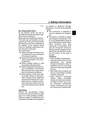
Helmet holders
The helmet holders are located on the
bottom of the passenger seat.
To secure a helmet to a helmet hold-
er
1. Remove the passenger seat. (See
page 3-17.)
2. Attach a helmet to a helmet hold-
er, and then securely install the
passenger seat. WARNING! Nev-
er ride with a helmet attached to
the helmet holder, since the hel-
met may hit objects, causing
loss of control and possibly an
accident.
[EWA10162]
To release a helmet from a helmet
holder
Remove the passenger seat, remove
the helmet from the helmet holder, and
then install the seat.
1. Helmet holder
1. Helmet
2. Passenger seat
1
1 2
UB6WE0E0.book Page 19 Friday, March 27, 2020 11:37 AM
Page 34 of 94

When storing documents or other
items in the storage")
Instrument and control functions
3-20
3
EAU62550
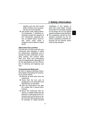
Storage compartment
The storage compartment is located
under the passenger seat. (See page
3-17.)
When storing documents or other
items in the storage compartment, be
sure to wrap them in a plastic bag so
that they will not get wet. When wash-
ing the vehicle, be careful not to let any
water enter the storage compartment.
WARNING
EWA15401
Do not exceed the maximum load of
160 kg (353 lb) for the vehicle.
EAU68143
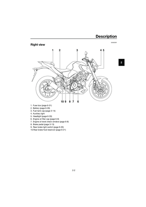
Adjusting the shock absorber
assembly
This shock absorber assembly is
equipped with a spring preload adjust-
ing ring.
NOTICE
ECA10102
To avoid damaging the mechanism,
do not attempt to turn beyond the
maximum or minimum settings.
Adjust the spring preload as follows.
TIP
For ABS models, remove the drive
chain guard by removing the bolts and
collars.
Turn the adjusting ring in direction (a)
to increase the spring preload.
Turn the adjusting ring in direction (b)
to decrease the spring preload.
Align the appropriate notch in the
adjusting ring with the position in-
dicator on the shock absorber.
Use the special wrench and the
extension bar included in the tool
kit to make the adjustment.
1. Storage compartment
1
1. Drive chain guard
2. Bolt and collar
2
1
UB6WE0E0.book Page 20 Friday, March 27, 2020 11:37 AM
Page 35 of 94
Instrument and control functions
3-21
3
TIP
For ABS models, be sure to install the
drive chain guard by installing the col-
lars and bolts, and then tighten the
bolts to the specified torque.
EAU84680
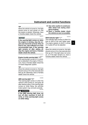
Luggage strap holders
Use the indicated strap points to se-
cure luggage ties to the vehicle.
1. Extension bar
2. Special wrench
3. Spring preload adjusting ring
4. Position indicator
Spring preload setting:
Minimum (soft):
1
Standard:
4
Maximum (hard):
7
Tightening torque:
Drive chain guard bolt:
10 N·m (1.0 kgf·m, 7.4 lb·ft)
7654321
4
(b)
(a)
32
1
1. Luggage strap holder
1
UB6WE0E0.book Page 21 Friday, March 27, 2020 11:37 AM
Page 36 of 94

Instrument and control functions
3-22
3
EAU15306
Sidestand
The sidestand is located on the left
side of the frame. Raise the sidestand
or lower it with your foot while holding
the vehicle upright.
TIP
The built-in sidestand switch is part of
the ignition circuit cut-off system,
which cuts the ignition in certain situa-
tions. (See the following section for an
explanation of the ignition circuit cut-
off system.)
WARNING
EWA10242
The vehicle must not be ridden with
the sidestand down, or if the side-
stand cannot be properly moved up
(or does not stay up), otherwise the
sidestand could contact the ground
and distract the operator, resulting
in a possible loss of control.
Yamaha’s ignition circuit cut-off
system has been designed to assist
the operator in fulfilling the respon-
sibility of raising the sidestand be-
fore starting off. Therefore, check
this system regularly and have a
Yamaha dealer repair it if it does not
function properly.
EAU64051
Ignition circuit cut-off system
This system prevents in-gear engine
starts unless the clutch lever is pulled
and the sidestand is up. Also, it will
stop the running engine should the
sidestand be lowered while the trans-
mission is in gear.
Periodically check the system via the
following procedure.
TIP
This check is most reliable if per-
formed with a warmed-up engine.
See pages 3-1 for switch opera-
tion information.
UB6WE0E0.book Page 22 Friday, March 27, 2020 11:37 AM
Page 37 of 94

Instrument and control functions
3-23
3
With the engine turned off:
1. Move the sidestand down.
2.Set engine stop switch to run position.
3. Turn main switch to on position.
4.Shift transmission into neutral.
5. Push the start switch.
Does the engine start?
With the engine still running:
6. Move the sidestand up.
7. Pull the clutch lever.
8.Shift transmission into gear.
9. Move the sidestand down.
Does the engine stall?
After the engine has stalled:
10. Move the sidestand up.
11. Pull the clutch lever.
12. Push the start switch.
Does the engine start?
The system is OK. The motorcycle can
be ridden.
The neutral switch may not be working.
The motorcycle should not be ridden
until checked by a Yamaha dealer.
The sidestand switch may not be
working.
The motorcycle should not be ridden
until checked by a Yamaha dealer.
The clutch switch may not be working.
The motorcycle should not be ridden
until checked by a Yamaha dealer.
WARNING
If a malfunction is found, have the
vehicle inspected before riding.
YES NO
YES NO
YES NO
UB6WE0E0.book Page 23 Friday, March 27, 2020 11:37 AM
Page 38 of 94

For your safety – pre-operation checks
4-1
4
EAU63441
Inspect your vehicle each time you use it to make sure the vehicle is in safe oper-
ating condition. Always follow the inspection and maintenance procedures and
schedules described in the Owner’s Manual.
WARNING
EWA11152
Failure to inspect or maintain the vehicle properly increases the possibility
of an accident or equipment damage. Do not operate the vehicle if you find
any problem. If a problem cannot be corrected by the procedures provided
in this manual, have the vehicle inspected by a Yamaha dealer.
Before using this vehicle, check the following points:
ITEM CHECKS PAGE
Fuel• Check fuel level in fuel tank.
• Refuel if necessary.
• Check fuel line for leakage.
• Check fuel tank breather hose and overflow hose for
obstructions, cracks or damage, and check hose con-
nections.3-15,
3-16
Engine oil• Check oil level in engine.
• If necessary, add recommended oil to specified level.
• Check vehicle for oil leakage.6-8
Coolant• Check coolant level in reservoir.
• If necessary, add recommended coolant to specified
level.
• Check cooling system for leakage.6-12
Front brake• Check operation.
• If soft or spongy, have Yamaha dealer bleed hydraulic
system.
• Check brake pads for wear.
• Replace if necessary.
• Check fluid level in reservoir.
• If necessary, add specified brake fluid to specified level.
• Check hydraulic system for leakage.6-20,
6-21
Rear brake• Check operation.
• If soft or spongy, have Yamaha dealer bleed hydraulic
system.
• Check brake pads for wear.
• Replace if necessary.
• Check fluid level in reservoir.
• If necessary, add specified brake fluid to specified level.
• Check hydraulic system for leakage.6-20,
6-21
Clutch• Check operation.
• Lubricate cable if necessary.
• Check lever free play.
• Adjust if necessary.6-18
UB6WE0E0.book Page 1 Friday, March 27, 2020 11:37 AM
Page 39 of 94

For your safety – pre-operation checks
4-2
4
Throttle grip• Make sure that operation is smooth.
• Check throttle grip free play.
• If necessary, have Yamaha dealer adjust throttle grip
free play and lubricate cable and grip housing.6-15,
6-25
Control cables• Make sure that operation is smooth.
• Lubricate if necessary.6-25
Drive chain• Check chain slack.
• Adjust if necessary.
• Check chain condition.
• Lubricate if necessary.6-23,
6-24
Wheels and tires•Check for damage.
• Check tire condition and tread depth.
• Check air pressure.
• Correct if necessary.6-16,
6-18
Brake and shift pedals• Make sure that operation is smooth.
• Lubricate pedal pivoting points if necessary.6-26
Brake and clutch le-
vers• Make sure that operation is smooth.
• Lubricate lever pivoting points if necessary.6-26
Sidestand• Make sure that operation is smooth.
• Lubricate pivot if necessary.6-27
Chassis fasteners• Make sure that all nuts, bolts and screws are properly
tightened.
• Tighten if necessary.—
Instruments, lights,
signals and switches• Check operation.
• Correct if necessary.—
Sidestand switch • Check operation of ignition circuit cut-off system.
• If system is not working correctly, have Yamaha dealer
check vehicle.3-22 ITEM CHECKS PAGE
UB6WE0E0.book Page 2 Friday, March 27, 2020 11:37 AM
Page 40 of 94

Operation and important riding points
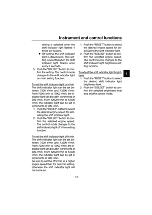
5-1
5
EAU15952
Read the Owner’s Manual carefully to
become familiar with all controls. If
there is a control or function you do not
understand, ask your Yamaha dealer.
WARNING
EWA10272
Failure to familiarize yourself with
the controls can lead to loss of con-
trol, which could cause an accident
or injury.
EAU16842
Engine break-in
There is never a more important period
in the life of your engine than the period
between 0 and 1600 km (1000 mi). For
this reason, you should read the fol-
lowing material carefully.
Since the engine is brand new, do not
put an excessive load on it for the first
1600 km (1000 mi). The various parts in
the engine wear and polish themselves
to the correct operating clearances.
During this period, prolonged full-throt-
tle operation or any condition that
might result in engine overheating
must be avoided.
EAU17094
0–1000 km (0–600 mi)
Avoid prolonged operation above 7000
r/min. NOTICE: After 1000 km (600
mi) of operation, the engine oil must
be changed and the oil filter car-
tridge or element replaced.
[ECA10303]
1000–1600 km (600–1000 mi)
Avoid prolonged operation above 8400
r/min.
1600 km (1000 mi) and beyond
The vehicle can now be operated nor-
mally.
NOTICE
ECA10311
Keep the engine speed out of
the tachometer red zone.
If any engine trouble should oc-
cur during the engine break-in
period, immediately have a
Yamaha dealer check the vehi-
cle.
UB6WE0E0.book Page 1 Friday, March 27, 2020 11:37 AM